US9217655B2 - Sensor system for determining at least one flow property of a fluid medium flowing in a main flow direction - Google Patents
Sensor system for determining at least one flow property of a fluid medium flowing in a main flow direction Download PDFInfo
- Publication number
- US9217655B2 US9217655B2 US13/526,422 US201213526422A US9217655B2 US 9217655 B2 US9217655 B2 US 9217655B2 US 201213526422 A US201213526422 A US 201213526422A US 9217655 B2 US9217655 B2 US 9217655B2
- Authority
- US
- United States
- Prior art keywords
- sensor
- air mass
- intake air
- flow direction
- main flow
- Prior art date
- Legal status (The legal status is an assumption and is not a legal conclusion. Google has not performed a legal analysis and makes no representation as to the accuracy of the status listed.)
- Expired - Fee Related, expires
Links
- 239000012530 fluid Substances 0.000 title claims abstract description 46
- 238000002485 combustion reaction Methods 0.000 claims description 9
- 230000003068 static effect Effects 0.000 claims description 8
- 238000007373 indentation Methods 0.000 claims description 4
- 239000002245 particle Substances 0.000 abstract description 26
- 238000013461 design Methods 0.000 description 17
- 239000003921 oil Substances 0.000 description 15
- 238000011109 contamination Methods 0.000 description 12
- 238000010438 heat treatment Methods 0.000 description 11
- 230000000694 effects Effects 0.000 description 9
- 238000000034 method Methods 0.000 description 9
- 230000002829 reductive effect Effects 0.000 description 9
- 230000035508 accumulation Effects 0.000 description 8
- 238000009825 accumulation Methods 0.000 description 8
- 230000008859 change Effects 0.000 description 8
- 238000011156 evaluation Methods 0.000 description 7
- 238000000926 separation method Methods 0.000 description 7
- 238000009826 distribution Methods 0.000 description 6
- 239000000428 dust Substances 0.000 description 6
- 230000004048 modification Effects 0.000 description 6
- 238000012986 modification Methods 0.000 description 6
- 238000004088 simulation Methods 0.000 description 6
- 239000004033 plastic Substances 0.000 description 5
- 230000009467 reduction Effects 0.000 description 5
- 239000000969 carrier Substances 0.000 description 4
- 239000004020 conductor Substances 0.000 description 4
- 239000000779 smoke Substances 0.000 description 4
- 238000011144 upstream manufacturing Methods 0.000 description 4
- 239000013598 vector Substances 0.000 description 4
- 229910010293 ceramic material Inorganic materials 0.000 description 3
- 230000036961 partial effect Effects 0.000 description 3
- 238000000917 particle-image velocimetry Methods 0.000 description 3
- 239000004071 soot Substances 0.000 description 3
- 230000007704 transition Effects 0.000 description 3
- 238000012800 visualization Methods 0.000 description 3
- XLYOFNOQVPJJNP-UHFFFAOYSA-N water Substances O XLYOFNOQVPJJNP-UHFFFAOYSA-N 0.000 description 3
- 230000007423 decrease Effects 0.000 description 2
- 239000003822 epoxy resin Substances 0.000 description 2
- 230000006872 improvement Effects 0.000 description 2
- 239000007788 liquid Substances 0.000 description 2
- 230000007774 longterm Effects 0.000 description 2
- 238000004519 manufacturing process Methods 0.000 description 2
- 239000002184 metal Substances 0.000 description 2
- 229920000647 polyepoxide Polymers 0.000 description 2
- 230000010349 pulsation Effects 0.000 description 2
- 230000002441 reversible effect Effects 0.000 description 2
- 239000007787 solid Substances 0.000 description 2
- 239000000126 substance Substances 0.000 description 2
- 230000008719 thickening Effects 0.000 description 2
- 238000012546 transfer Methods 0.000 description 2
- 238000013022 venting Methods 0.000 description 2
- XUIMIQQOPSSXEZ-UHFFFAOYSA-N Silicon Chemical compound [Si] XUIMIQQOPSSXEZ-UHFFFAOYSA-N 0.000 description 1
- 239000000853 adhesive Substances 0.000 description 1
- 238000004026 adhesive bonding Methods 0.000 description 1
- 230000001070 adhesive effect Effects 0.000 description 1
- 238000013459 approach Methods 0.000 description 1
- 230000008901 benefit Effects 0.000 description 1
- 230000015572 biosynthetic process Effects 0.000 description 1
- 239000002131 composite material Substances 0.000 description 1
- 239000007789 gas Substances 0.000 description 1
- 230000002452 interceptive effect Effects 0.000 description 1
- 238000005304 joining Methods 0.000 description 1
- 239000000463 material Substances 0.000 description 1
- 230000007246 mechanism Effects 0.000 description 1
- 230000008569 process Effects 0.000 description 1
- 229910052710 silicon Inorganic materials 0.000 description 1
- 239000010703 silicon Substances 0.000 description 1
- 239000002689 soil Substances 0.000 description 1
- 230000007480 spreading Effects 0.000 description 1
- 238000003892 spreading Methods 0.000 description 1
- 230000000087 stabilizing effect Effects 0.000 description 1
Images


Classifications
-
- G—PHYSICS
- G01—MEASURING; TESTING
- G01F—MEASURING VOLUME, VOLUME FLOW, MASS FLOW OR LIQUID LEVEL; METERING BY VOLUME
- G01F1/00—Measuring the volume flow or mass flow of fluid or fluent solid material wherein the fluid passes through a meter in a continuous flow
- G01F1/68—Measuring the volume flow or mass flow of fluid or fluent solid material wherein the fluid passes through a meter in a continuous flow by using thermal effects
- G01F1/684—Structural arrangements; Mounting of elements, e.g. in relation to fluid flow
- G01F1/6842—Structural arrangements; Mounting of elements, e.g. in relation to fluid flow with means for influencing the fluid flow
-
- G—PHYSICS
- G01—MEASURING; TESTING
- G01F—MEASURING VOLUME, VOLUME FLOW, MASS FLOW OR LIQUID LEVEL; METERING BY VOLUME
- G01F1/00—Measuring the volume flow or mass flow of fluid or fluent solid material wherein the fluid passes through a meter in a continuous flow
- G01F1/68—Measuring the volume flow or mass flow of fluid or fluent solid material wherein the fluid passes through a meter in a continuous flow by using thermal effects
- G01F1/684—Structural arrangements; Mounting of elements, e.g. in relation to fluid flow
- G01F1/6845—Micromachined devices
-
- G—PHYSICS
- G01—MEASURING; TESTING
- G01F—MEASURING VOLUME, VOLUME FLOW, MASS FLOW OR LIQUID LEVEL; METERING BY VOLUME
- G01F1/00—Measuring the volume flow or mass flow of fluid or fluent solid material wherein the fluid passes through a meter in a continuous flow
- G01F1/68—Measuring the volume flow or mass flow of fluid or fluent solid material wherein the fluid passes through a meter in a continuous flow by using thermal effects
- G01F1/684—Structural arrangements; Mounting of elements, e.g. in relation to fluid flow
- G01F1/688—Structural arrangements; Mounting of elements, e.g. in relation to fluid flow using a particular type of heating, cooling or sensing element
- G01F1/69—Structural arrangements; Mounting of elements, e.g. in relation to fluid flow using a particular type of heating, cooling or sensing element of resistive type
- G01F1/692—Thin-film arrangements
-
- G—PHYSICS
- G01—MEASURING; TESTING
- G01F—MEASURING VOLUME, VOLUME FLOW, MASS FLOW OR LIQUID LEVEL; METERING BY VOLUME
- G01F5/00—Measuring a proportion of the volume flow
-
- F—MECHANICAL ENGINEERING; LIGHTING; HEATING; WEAPONS; BLASTING
- F15—FLUID-PRESSURE ACTUATORS; HYDRAULICS OR PNEUMATICS IN GENERAL
- F15D—FLUID DYNAMICS, i.e. METHODS OR MEANS FOR INFLUENCING THE FLOW OF GASES OR LIQUIDS
- F15D1/00—Influencing flow of fluids
- F15D1/02—Influencing flow of fluids in pipes or conduits
Definitions
- the present invention relates to a sensor system for determining at least one flow property of fluid medium.
- the flow properties may be basically any given physically and/or chemically measurable properties which qualify or quantify a flow of the fluid medium.
- a flow rate and/or a mass flow and/or a volume flow may be involved.
- hot film air mass meters as described, for example, in Konrad Reif (publisher): Sensoren im Kraftchrist [Sensors in Motor Vehicles ], Edition 1, 2010, pages 146-148.
- These types of hot film air mass meters are generally based on a sensor chip, in particular a silicon sensor chip, having a sensor diaphragm as a measuring surface or sensor area over which the flowing fluid medium is able to flow.
- the sensor chip generally includes at least one heating element and at least two temperature sensors which are situated, for example, on the measuring surface of the sensor chip.
- a mass flow and/or volume flow of the fluid medium may be deduced based on an asymmetry of the temperature profile detected by the temperature sensors, which is influenced by the flow of the fluid medium.
- Hot film air mass meters are usually designed as plug-in sensors which are permanently or replaceably introducible into a flow tube.
- this flow tube may be an intake tract of an internal combustion engine.
- a partial flow of the medium flows through at least one main channel provided in the hot film air mass meter.
- a bypass channel is provided between the inlet and the outlet of the main channel.
- the bypass channel is designed in such a way that it has a curved section for deflecting the partial flow of the medium which has entered through the inlet of the main channel, the further course of the curved section merging into a section in which the sensor chip is situated.
- the latter-mentioned section represents the actual measuring channel in which the sensor chip is situated.
- a means is provided in the bypass channel which conducts the flow and counteracts separation of the flow of the media partial flow from the channel walls of the measuring channel.
- the inlet area of the main channel is provided with angled or curved surfaces which are designed in such a way that medium flowing into the inlet area is diverted from the portion of the main channel leading to the sensor chip.
- liquid or solid particles contained in the medium may not reach the sensor chip due to their mass inertia, and may soil the sensor chip.
- the signal drift relates to the deviation, for example of the mass flow of the medium, in the sense of changing the characteristic curve relationship between the mass flow actually occurring and the signal to be emitted within the scope of calibration during manufacture.
- the sensor signals which are output in a rapid time sequence are taken into account, whereas the characteristic curve drift or signal drift refers to a change in the mean value.
- a sensor carrier having a sensor chip mounted thereon or inserted therein generally protrudes into the measuring channel.
- the sensor chip may be glued into or onto the sensor carrier.
- the sensor carrier may form a unit with, for example, a base plate made of metal on which an electronics system and a control and evaluation circuit in the form of a printed circuit board may be glued.
- the sensor carrier may be designed as a molded-on plastic part of an electronic module.
- the sensor chip and the control and evaluation circuit may be connected to one another via bond connections, for example.
- the electronic module produced in this way may, for example, be glued into a sensor housing, and the entire plug-in sensor may be closed by covers.
- the hot film air mass meter is able to deliver an air mass signal which is as free of interference as possible, flow to the plug-in sensor and through the measuring channel in the plug-in sensor, and in particular over the measuring surface of the sensor chip, which is as uniform as possible, is important. It has been shown that the contour of the leading edge of the sensor carrier which protrudes into the measuring channel is of crucial importance for the signal quality of the sensor system. Thus, for example, it is proposed in published German patent application document DE 103 455 084 A1 that the leading edge of the sensor carrier to have a rounded design to improve the flow quality at the sensor carrier and at the sensor chip, and to avoid pulsing, nonstationary separations at the surface of the sensor chip.
- Published German patent application document DE 10 2008 042 155 A1 discloses a sensor system for determining at least one parameter of a fluid medium, in particular an intake air mass of an internal combustion engine, flowing through a channel.
- the sensor system has at least one sensor chip situated in the channel for determining the parameter of the fluid medium.
- the sensor chip is accommodated in a sensor carrier which protrudes into the channel.
- the sensor carrier has a leading edge, situated transverse to the flow of the fluid medium, which has at least one vortex generator that is set up to form longitudinal vortices in the flowing fluid medium in the region of the sensor carrier.
- These longitudinal vortices require an improved intermixture between rapid fluid more remote from the wall and slower fluid, close to the wall and in danger of separation, in the region of the sensor carrier.
- the flow over these flow regions must be as stable as possible from a topological standpoint.
- the contamination by particles may result in an altered topology over the long term, i.e., a change in the flow-defining structure at certain points, for example specks of dust, vortex foci, separation lines, and the like, or may result in a quantitative change in the flow variables.
- a sensor system for determining at least one flow property of a fluid medium flowing in a main flow direction is therefore proposed, via which the disadvantages of known methods and strategies may be at least largely avoided, and in which a velocity field, in particular on the sensor chip side of the sensor carrier, which has long-term stability, in particular with regard to the particle contamination, may be generated.
- the sensor system for determining at least one parameter of a fluid medium, in particular an intake air mass of an internal combustion engine, flowing through a channel has at least one sensor chip situated in the channel for determining the parameter of the fluid medium, the sensor chip being accommodated in a sensor carrier which protrudes into the channel, and the sensor carrier having a leading edge situated transverse to the main flow direction of the fluid medium, at least one vortex generator being provided at least in the region of the leading edge and being set up for forming secondary flows, in particular in the form of vortices, in the flowing fluid medium in the region of the sensor carrier, in particular in the region of the sensor chip, preferably in the immediate proximity of a sensor area, in particular of a micromechanical sensor diaphragm, the secondary flows extending in a plane essentially perpendicular to the main flow direction of the fluid medium.
- the secondary flow is designed as a vortex, the vortex axis extends parallel to the main flow direction.
- the sensor carrier may essentially define a plane in the main flow direction, and the at least one vortex generator may be designed in the form of at least one projection, such as a web or a ramp, for example, which protrudes from the plane of the sensor carrier.
- the at least one vortex generator may be provided, at least in places, along the leading edge and/or along a rear edge of the sensor carrier as viewed in the main flow direction of the fluid medium.
- the at least one turbulator may be situated transverse to the main flow direction.
- the at least one vortex generator may extend, at least in places, from the leading edge to a rear edge of the sensor carrier as viewed in the main flow direction of the fluid medium.
- the at least one vortex generator may be essentially semicircular or rectangular.
- the sensor chip may have at least one sensor area, and at least two vortex generators may be situated in such a way that at least the sensor area projects into a plane perpendicular to the flow of the fluid medium, situated between the vortex generators.
- the at least two vortex generators may be designed in such a way that due to multiple vortices, the secondary flows, at least in the region of the sensor area, are provided with the particular vortex axis parallel to the main flow direction of the fluid medium and in the mutually opposite rotational direction, i.e., with oppositely directed vortex axes.
- Multiple vortex generators may be situated extending in the main flow direction and parallel to one another.
- At least one vortex generator may be designed as an indentation in the sensor carrier, preferably at the front edge of the sensor carrier which extends in the main flow direction. At least one indentation in the sensor carrier may extend in the main flow direction and, projected into the plane perpendicularly to the main flow direction, may be located laterally adjacent to the sensor area.
- the main flow direction is understood to mean the local flow direction of the fluid medium at the location of the sensor or of the sensor system, whereby, for example, local irregularities such as turbulences may continue to be disregarded.
- the main flow direction may thus be understood to mean the local averaged transport direction of the flowing fluid medium.
- transverse to the main flow direction is understood to mean perpendicular or essentially perpendicular, for example having an orientation which deviates by no more than 10° from the vertical with respect to the local main flow direction.
- “essentially” is understood to mean an orientation which deviates by no more than 20°, preferably by no more than 10°, and particularly preferably by no more than 5°, and/or by no more than 20%, in particular by no more than 10%, and particularly preferably by no more than 5%, of the particular stated reference direction, reference plane, or reference shape.
- an “essentially parallel” orientation is an orientation which deviates from parallelism by no more than the stated tolerances.
- secondary flow is understood to mean a comparatively low velocity, i.e., the secondary velocity, in addition to the main flow in a plane essentially transverse to the main flow direction.
- a vortex is understood to mean a complete or partially circular flow or approximately circular flow of a fluid.
- the vortex axis is understood to mean the axis about which the circular flow runs. This axis may extend, for example, parallel to a vortex vector of the vortices.
- transverse vortices since the mentioned vortex axis of the vortices extends essentially parallel to the main flow direction of the fluid, and the secondary flows of the vortex form as circular flow or approximately circular flow around the vortex axis, the vortex generator may have various designs.
- the vortex generator may be set up in such a way, for example, that at least two adjacent regions having different static pressures exist in at least one plane perpendicular to the main flow direction. This may be achieved in such a way, for example, that the vortex generator is set up to generate at least two adjacent regions having different flow cross sections, for example via different constrictions in a region through which the flow passes, so that the flow passes through these regions at different velocities according to the Bernoulli equation, and different pressures are formed in these regions. The formation of the secondary flows may then be a result of a compensation for these different pressures.
- the vortex generator may be designed in such a way that at least two sections exist which have a different distance between the leading edge and a wall of the channel, i.e., sections having different flow cross sections.
- transverse vortices may be visualized, for example, with the aid of numerical fluid mechanics simulations in order to visually represent their existence.
- the vortices may be visualized, for example, with the aid of smoke and/or so-called smoke wire visualization, for example using a camera that records smoke turbulences in the flow and/or downstream from the vortex generator.
- smoke wire visualization a wire is provided with an oil-containing substance, for example, and is heated. During heating of the wire the substance evaporates, and upon separating from the wire immediately condenses in the surroundings, and the individual condensing particles become visible. The flow lines composed of these particles are then individually detectable, thus allowing good observation of the flow profile.
- PIV particle image velocimetry
- places is understood to mean an arrangement which does not extend completely along or over the particular stated length or extension of the reference component or the direction, but, rather, which is provided only in sections or partially.
- the arrangement itself may have interruptions or recesses so that it has a segmented design.
- the sensor carrier may be completely or partially designed as a printed circuit board or may be part of a printed circuit board.
- the printed circuit board may have an extension which forms the sensor carrier and protrudes into the channel, for example the measuring channel of a hot film air mass meter.
- the remaining portion of the printed circuit board may be accommodated, for example, in an electronics compartment, or in a housing of the sensor system or of a plug-in sensor of the sensor system.
- a printed circuit board is generally understood to mean an essentially plate-shaped element which may also be used as a support for electronic structures, for example circuit board conductors, terminal contacts, or the like, and which preferably also has one or more of these types of structures. In principle, at least slight deviations from the plate shape are also considered, and conceptually are included with same.
- the printed circuit board may be made, for example, of a plastic material and/or a ceramic material, an epoxy resin, for example, in particular a fiber-reinforced epoxy resin.
- the printed circuit board may be designed, for example, as a printed circuit board having circuit board conductors, in particular printed circuit board conductors (PCB).
- the electronic module of the sensor system may be greatly simplified, and a base plate and a separate sensor carrier, for example, may be dispensed with.
- the base plate and sensor carrier may be replaced by a single printed circuit board on which, for example, a control and evaluation circuit of the sensor system may also be completely or partially situated.
- This control and evaluation circuit of the sensor system is used to control the at least one sensor chip and/or the evaluation of the signals generated by this sensor chip.
- the sensor system may in particular have at least one housing, the channel being provided in the housing.
- the channel may include a main channel and a bypass channel or measuring channel, whereby the sensor carrier and the sensor chip may be situated in the bypass channel or measuring channel, for example.
- the housing may have an electronics compartment which is separate from the bypass channel, the electronic module or the printed circuit board essentially being accommodated in the electronics compartment.
- the sensor carrier may then be designed as an extension of the printed circuit board which protrudes into the channel. In contrast to the complicated electronic modules known from the related art, this system is comparatively easy to implement technically.
- the sensor carrier may be designed, at least partially, as the multilayer sensor carrier.
- the sensor carrier may be designed in a so-called multilayer technique, and have two or more carrier layers joined together.
- these carrier layers may once again be made of a metal, a plastic, or a ceramic material or a composite material, and joined together using joining techniques, for example gluing.
- the leading edge may have an at least partially stepped design against the main flow direction of the fluid medium as the result of different dimensioning of the carrier layers.
- the profiles may thus be implemented in at least an approximately stepped manner.
- profiles in a section plane perpendicular to the extension plane of the sensor carrier may thus be provided with a shape that is rectangular or, approximated by a stepped shape, at least approximately circular, rounded, or wedge-shaped.
- the sensor chip may be situated on or in the sensor carrier in such a way that it is oriented perpendicularly to the local main flow direction.
- the sensor chip may have a rectangular design, one side of this rectangle being perpendicular or essentially perpendicular, for example with an orientation that deviates by no more than 10 degrees from the vertical with respect to the local main flow direction.
- the sensor chip may be electrically contacted via at least one electrical connection.
- the sensor carrier in particular a printed circuit board which forms the sensor carrier or an extension of this printed circuit board, may have one or multiple printed conductors and/or contact pads which are connected to corresponding contacts on the sensor chip, for example with the aid of a bonding process.
- the electrical connection may be protected by at least one cover and be separated from the fluid medium.
- This cover may in particular be designed as a so-called “glob top,” for example as plastic drops and/or adhesive drops, which covers the electrical connection, for example the bond wires.
- influences on the flow by the electrical connection may also be avoided in this way, since the glob top has a smooth surface.
- the sensor chip may have at least one sensor area. This sensor area may be, for example, a sensor surface made, for example, of a porous ceramic material, and/or in particular may be a sensor diaphragm.
- changes in the velocity field may be reduced compared to a new or initial state of the sensor system; in particular, however, regions of low velocity in the particle gathering area of the sensor area may be avoided or reduced. Over the service life of the sensor system, such low-velocity regions may be used as a collection point for increasingly larger numbers of particles. Since the particles change the tendency toward contamination and the heat transfer to the air, the following effects in particular are achieved by individual measures or by a combination of measures. The growth of the boundary layer due to contamination is avoided or at least reduced, since an effective reduction in the flow pulse in the vicinity of the sensor area is thus achieved. The vortex foci, specks of dust, or collection points which form in the region around the sensor area are avoided or at least reduced.
- the aim is to avoid or at least reduce low-velocity regions which result from other causes.
- the measures are also suitable for nonstationary reverse flow states, i.e., pulsation in the intake tract. Via appropriate designs at the front and/or rear edge of the sensor carrier, the aim ideally is to adapt the bandwidths of the velocity fields to one another during the forward and reverse flow. As a side effect, the stabilizing measures result in smaller velocity fluctuations for the instantaneously measured mean value in the region of the sensor area, resulting in lower signal noise and better reproducibility.
- secondary velocities may be generated or induced in the main flow, and/or low-velocity regions may be avoided on and in the immediate proximity of the sensor area, in particular of the micromechanical sensor diaphragm.
- a topologically more exact definition of the flow field including the boundary layer flow in the immediate proximity of the sensor area, in particular of the sensor diaphragm, is possible, i.e., avoidance of characteristics of the flow-defining structures, which change with the mass flow or flow states, such as, for example, stagnation points and saddle points, separation lines, vortex foci, variation of the wall shear stress over time, and the like.
- avoidance of or reduction in the particle accumulation as well as the harmonization of the flow over the sensor area are achieved by the measures according to the present invention.
- FIG. 1 shows a perspective illustration of a sensor system.
- FIG. 2 shows a view of a sensor carrier together with a sensor chip in a channel, viewed in the main flow direction.
- FIG. 3 shows a top view of a sensor carrier together with a sensor chip (back side) in a channel.
- FIG. 4 shows an enlarged top view of an unclosed sensor housing together with the channel structure, and of the sensor carrier together with the sensor chip, and a schematic illustration of the flow through the channel.
- FIG. 5 shows an enlarged illustration of an electronic module of the sensor system, together with the sensor carrier and the installed sensor chip.
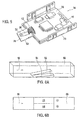
- FIG. 6A shows a perspective view of a ramp pair for generating a secondary flow in a rectangular channel.
- FIG. 6B shows a top view of the ramp pair in the rectangular channel, and a schematic illustration of the distribution of the static pressure.
- FIG. 7A shows a perspective view of a secondary flow field downstream from the ramp pair in the rectangular channel.
- FIG. 7B shows a view of the secondary flow field downstream from the ramp pair in the rectangular channel, viewed in the main flow direction.
- FIG. 7C shows another perspective view of the ramp pair, with an illustration of the velocities and flow lines.
- FIG. 7D shows an enlarged detail of the secondary flow field in the region of the transition between the ramps.
- FIG. 8A shows a top view of sensor chips of two different sensor carriers, and the illustration of a temperature distribution in the main flow direction, without chip heating.
- FIG. 8B shows a top view of sensor chips of two different sensor carriers, and the illustration of two temperature distributions in the main flow direction, with chip heating.
- FIG. 9A shows a top view of a first specific embodiment of a sensor carrier.
- FIG. 9B shows a view of the first specific embodiment of the sensor carrier, viewed in the main flow direction.
- FIG. 10 shows a top view of a second specific embodiment of a sensor carrier.
- FIG. 11 shows a top view of a third specific embodiment of a sensor carrier.
- FIG. 12 shows a top view of a fourth specific embodiment of a sensor carrier.
- FIG. 13 shows a top view of a fifth specific embodiment of a sensor carrier.
- FIG. 14 shows a view of a sixth specific embodiment of a sensor carrier, viewed in the main flow direction.
- FIG. 15 shows a view of a seventh specific embodiment of a sensor carrier, viewed in the main flow direction.
- FIG. 16 shows a perspective view of an eighth specific embodiment of a sensor carrier.
- FIG. 17 shows a view of a ninth specific embodiment of a sensor carrier, viewed in the main flow direction.
- FIG. 18A shows two results of a flow simulation, using different air mass flows, without a sensor system according to the present invention, in which the velocity field in a sensor area, the wall shear stress on the sensor carrier, the isosurface of the vortex strength, and the wall flow lines are illustrated.
- FIG. 18B shows enlarged illustrations of the velocity fields in FIG. 18A , viewed in the main flow direction.
- FIG. 1 shows a sensor system 10 for determining a parameter of a fluid medium.
- sensor system 10 is designed as a hot film air mass meter, and includes a plug-in part 12 which may plugged into a flow tube, for example, in particular an intake tract of an internal combustion engine.
- a channel structure 14 apparent in FIG. 1 or FIG. 4 , is accommodated in plug-in part 12 , through which a representative quantity of the fluid medium is able to flow through an inlet opening 16 , which in the inserted state points toward a main flow direction 18 of the fluid medium.
- FIG. 4 shows an enlarged detail of plug-in part 12 in the region of the channel structure.
- Channel structure 14 has a main channel 20 which opens into a main flow outlet 22 on the bottom side, relative to the illustration in FIG. 1 , of plug-in part 12 , and a bypass channel or measuring channel 24 which branches off from main channel 20 and opens into a bypass channel or measuring channel outlet 26 likewise situated on the bottom side, relative to the illustration in FIG. 1 , of plug-in part 12 , as is apparent from FIG. 4 .
- FIG. 2 shows the view of sensor carrier 28 in measuring channel 24 in the main flow direction.
- FIG. 3 shows a top view of the arrangement of sensor carrier 28 in measuring channel 24 .
- a sensor chip 30 is embedded in this sensor carrier 28 in such a way that the fluid medium flows over a sensor diaphragm 32 , which is designed as a sensor area of sensor chip 30 .
- sensor carrier 28 together with sensor chip 30 is an integral part of an electronic module 34 , illustrated in enlarged scale.
- This electronic module 34 has a bent base plate 36 as the sensor carrier, and a printed circuit board 38 mounted, for example glued, thereon, having a control and evaluation circuit 40 .
- Sensor carrier 28 may be molded onto base plate 36 , for example as a plastic component.
- the sensor chip is electrically connected to control and evaluation circuit 40 via electrical connections 42 , in the present case designed as wire bonding, as is apparent in particular from FIG. 5 .
- Resulting electronic module 34 is introduced, for example glued, into an electronics compartment 44 in a housing 46 of plug-in part 12 in which channel structure 14 is also provided, as is apparent in FIG. 1 . This is carried out in such a way that sensor carrier 28 protrudes into channel structure 14 .
- Electronics compartment 44 and channel structure 14 are subsequently closed by lid 48 .
- Sensor carrier 28 which is molded onto base plate 36 as an injection-molded component, for example, or which may be an integral part of base plate 36 or printed circuit board 38 , is provided with a leading edge 50 , which may have a rounded design, as is apparent from FIG. 2 , for example.
- this leading edge 50 may be implemented similarly to an airfoil with a constant contour.
- the specific embodiments of sensor carrier 28 according to the present invention are described in greater detail below. First, however, the fluid mechanics correlations of cross-sectional changes in a channel, for example measuring channel 24 , with the aid of vortex generators, for example ramps, steps, or blocks, are explained in order to clarify the conceptual approach, underlying the present invention, of the various specific embodiments of the sensor carrier. In particular, the explanation as an example is intended to illustrate the principle of using cross-sectional changes of certain sections or regions in a channel to intentionally form secondary flows such as longitudinal vortices, for example.
- FIGS. 6A and 6B show a ramp pair 52 , 54 of different heights in a rectangular channel 56 , FIG. 6A illustrating an arrangement in perspective view with flow from the left, and FIG. 6B illustrating a corresponding top view with a schematic illustration of the distribution of the static pressure.
- main flow direction 18 is parallel to the longitudinal axis of rectangular channel 56 from left to right according to the illustrations in FIGS. 6A and 6B .
- the static pressure decreases in the region of a flow which is accelerated to a higher velocity. The flow is accelerated to a greater degree in the region of higher ramp 52 than in the region of lower ramp 54 .
- the static pressure is lowered to a greater degree in the region of higher ramp 52 .
- the static pressure in the region of lower ramp 54 is greater than that in the region of higher ramp 52 .
- This is indicated by the symbols “+” and “ ⁇ ” in FIG. 6B .
- velocity components also referred to as secondary velocity components, result in the plane perpendicular to main flow direction 18 , and vortices 55 A, 55 B form downstream from ramps 52 , 54 , respectively, as is apparent from FIG. 7A or FIG. 7B , for example, in order to equalize the pressures.
- the vortex axis of vortices 55 A, 55 B extends essentially parallel to main flow direction 18 .
- two vortices 55 A, 55 B result in this arrangement, a larger vortex 55 A having a clockwise rotational direction and extending essentially over the entire cross section of channel 56 , and a smaller vortex 55 B, in a region downstream from larger ramp 52 having a counterclockwise rotational direction, and whose profile in terms of surface area or extent of spreading being essentially identical to the cross-sectional area of higher ramp 52 .
- FIG. 7A shows a perspective view of this type of velocity field of vortices 55 A, 55 B in a plane perpendicular to main flow direction 18
- FIG. 7B shows a top view of this projected velocity field plane of these vortices 55 A, 55 B downstream from ramp pair 52 , 54 , respectively, as a result of a numerical flow simulation.
- the regions of the particular velocity fields are surrounded by thin lines for better distinguishability and delimitability.
- the lengths of the vectors of the velocity field indicate the particular magnitude of the velocity projected into the plane, a greater length of a vector indicating a higher velocity.
- FIG. 7C shows the velocities and the flow lines in a perspective side view at the level of the particular ramp, the differently dotted regions of the flow lines indicating the particular magnitude of the velocity.
- main flow direction 18 being indicated on the axis denoted by X, and the axes denoted by Y and Z defining a plane perpendicular to main flow direction 18 .
- an orientation transverse to main flow direction 18 is therefore located in the Y-Z plane.
- the secondary velocities in the stated plane perpendicular to the main flow, i.e., in the Y-Z plane of FIG. 7C are also low. Thus, there is a higher probability of accumulation of particles in such low-velocity regions.
- the arrangement of micromechanical sensor diaphragm 32 would therefore most probably result in increased contamination and characteristic curve drift.
- FIG. 7D schematically shows a detail of the transition from such a higher projection to a lower projection, projected into the stated plane perpendicular to main flow direction 18 , and one possible arrangement of a micromechanical sensor diaphragm 32 in the region of the secondary velocities of larger vortex 55 A.
- the secondary flow which is present even at low velocities, there should be no accumulation of particles in the region of sensor diaphragm 32 ; instead, the particles should be carried away from sensor diaphragm 32 due to generated vortex 55 A.
- overall rectangular channel 56 at least a pronounced secondary flow results in the plane perpendicular to main flow direction 18 due to ramps 52 , 54 , which are large relative to the channel dimensions.
- the present invention is therefore directed to influencing the path of the light particles which are not filtered out by the deflection by centrifugal force or by adherence to the bypass channel walls, or which have extreme deviations from main flow direction 18 due to bouncing against the bypass channel walls.
- the aim is to keep such particles away from sensor diaphragm 32 as the result of the geometrically induced secondary velocities.
- FIG. 8A shows two top views of a sensor chip 30 of two different sensor carriers 28 without chip heating, main flow direction 18 being indicated by an arrow, and a temperature distribution over main flow direction 18 being plotted on the axis denoted by X.
- FIG. 8B shows two top views of a sensor chip 30 of two different sensor carriers 28 with chip heating, main flow direction 18 being indicated by an arrow, and two associated temperature distributions as the result of different heating modes over main flow direction 18 being plotted on the axis denoted by X.
- chip heating is switched on, a reduction in the entry of oil is clearly apparent, as is discernible from FIG. 8B , for example.
- sensor carrier 28 uses the principle of the targeted change in flow with the aid of design measures, as described in detail below.
- Use of the change in geometry is conceivable for the inflow side, which is important for normal operation, as well as for the outflow side, which is important for pulsing flow.
- FIG. 9A shows a top view of a first specific embodiment of a sensor carrier 28 according to the present invention
- FIG. 9B shows a side view, viewed in main flow direction 18
- two vortex generators 58 which are set up to generate secondary flows or to induce same in the main flow direction, and which therefore may also be referred to as secondary flow generators, are provided, and as cuboidal and/or web-shaped projections protrude essentially perpendicularly from the plane of sensor carrier 28 .
- vortex generators 58 are situated on sensor carrier 28 , in the region of leading edge 50 , in such a way that sensor diaphragm 32 projects into the plane perpendicularly to main flow direction 18 , situated between vortex generators 58 , as is apparent from the illustration in FIG. 9B .
- one vortex generator 58 is thus located to the left of sensor diaphragm 32
- the other vortex generator 58 is located to the right of sensor diaphragm 32 .
- vortex generators 58 have a relatively small depth; i.e., their dimension viewed in main flow direction 18 is relatively small compared to their other dimensions.
- Vortex generators 58 Downstream from these vortex generators 58 as viewed directly in main flow direction 18 , low-velocity regions 59 , indicated by two ellipses, result on sensor carrier 28 .
- Vortex generators 58 generate regions of higher velocity and lower pressure due to the thickening of the boundary layers in their trailings to the left and right of sensor diaphragm 32 , and therefore slightly farther downstream than the regions indicated by the ellipses, so that the flow region upstream from and above sensor diaphragm 32 , starting from the center of sensor diaphragm 32 , has outwardly directed secondary velocities.
- oppositely rotating vortices 55 result to the left and right of sensor diaphragm 32 whose vortex axes extend essentially parallel to the main flow direction and which drive the particles from sensor diaphragm 32 outwardly and upwardly in each case, i.e., into the more rapid main flow.
- the height and the width, the extension in main flow direction 18 , or the position of the inner edge of the vortex generators relative to the position of sensor diaphragm 32 may vary.
- FIG. 10 shows an illustration of a second specific embodiment which corresponds to the illustration in FIG. 9A .
- the second specific embodiment represents a modification of the first specific embodiment. Only the differences from the first specific embodiment are described below, and identical components are provided with the same reference numerals.
- vortex generators 58 have a greater depth in main flow direction 18 . Vortex generators 58 of the second specific embodiment bring about similar effects as those described for the first specific embodiment. The strength of the secondary flow should increase compared to the first specific embodiment.
- FIG. 11 A third specific embodiment is shown in FIG. 11 in a top view. Only the differences from the preceding specific embodiments are described below, and identical components are provided with the same reference numerals.
- a plurality of vortex generators 58 is provided, the vortex generators being situated on sensor carrier 28 , parallel to one another in main flow direction 18 , and protruding essentially perpendicularly from the plane of sensor carrier 28 .
- Vortex generators 58 are designed as cuboidal and/or web-shaped projections, for example.
- vortex generators 58 which are located in the region of sensor chip 30 in a direction transverse to main flow direction 18 , viewed in or parallel to the plane of sensor carrier 28 , each have an interruption or a recess within which sensor chip 30 is situated.
- vortex generators 58 which have an interruption or a recess do not terminate in flush alignment with sensor chip 30 , but, rather, are located at a small distance from sensor chip 30 in and against main flow direction 18 .
- vortex generators 58 In the remaining regions of sensor carrier 28 , vortex generators 58 have a consistent design from leading edge 50 to the rear edge of sensor carrier 28 , viewed in main flow direction 18 . A single or multiple interruption is conceivable.
- vortex generators 58 have a relatively small width: i.e., their dimension transverse to main flow direction 18 in or parallel to the plane of the sensor carrier is relatively small compared to their other dimensions.
- grooves and/or protruding steps may be provided, which due to their consistency conduct the flow, and which in particular in the case of pulsation are designed to prevent uncontrolled lateral entry of particles. At the same time, these types of grooves are used for runoff of any oil which is deposited despite chip heating.
- the height of the protruding steps may be constant, or may also increase in a curved manner in main flow direction 18 , or in some cases may assume other suitable profiles, in particular in the vicinity of sensor diaphragm 32 .
- FIG. 12 shows an illustration of a fourth specific embodiment corresponding to the illustration in FIG. 11 .
- the fourth specific embodiment represents a modification of the third specific embodiment. Only the differences from the third specific embodiment are described below, and identical components are provided with the same reference numerals.
- Vortex generators 58 have a greater width compared to the third specific embodiment.
- vortex generators 58 which have an interruption or a recess, terminate in flush alignment with sensor chip 30 .
- Vortex generators 58 in the fourth specific embodiment bring about similar effects as those described for the third specific embodiment.
- a fifth specific embodiment is shown in FIG. 13 in a top view. Only the differences from the preceding specific embodiments are described below, and identical components are provided with the same reference numerals.
- two vortex generators 58 which are designed as spaced-apart milled grooves or recesses, for example having a rectangular, semicircular, or square design in a top view, in sensor carrier 28 are located in the region of leading edge 50 .
- vortex generators 58 are situated on sensor carrier 28 in the region of leading edge 50 in such a way that sensor diaphragm 32 , which projects into a plane perpendicular to main flow direction 18 , is situated between vortex generators 58 .
- the fifth specific embodiment produces a thicker boundary layer in the trailings of milled grooves 58 , downstream from milled grooves 58 at the leading edge, compared to the flow course outside milled grooves 58 at leading edge 50 , which is rounded similar to an airfoil profile, and thus has the same effect as an actually present step geometry according to the above-described specific embodiments.
- Secondary velocities and oppositely rotating vortices 55 each having a vortex axis parallel to main flow direction 18 , likewise form as described above.
- FIG. 14 A sixth specific embodiment is shown in FIG. 14 in a view in the main flow direction. Only the differences from the preceding specific embodiments are described below, and identical components are provided with the same reference numerals.
- two vortex generators 58 are provided on sensor carrier 28 , parallel to one another in main flow direction 18 , and protrude essentially perpendicularly from the plane of sensor carrier 28 .
- Vortex generators 58 are designed, for example, as cuboidal and/or web-shaped projections.
- vortex generators 58 are situated on sensor carrier 28 in such a way that sensor diaphragm 32 , which projects in a plane perpendicular to main flow direction 18 , is situated between vortex generators 58 .
- vortex generators 58 are comparatively high and wide.
- FIG. 14 not only variations in the position and the number, but also asymmetrical arrangements due to the incoming flow which concern the width, height, or height profile are conceivable.
- other shapes are conceivable in the shape transverse to main flow direction 18 .
- vortex generators 58 shown as projections may also be semicircular, or be provided with radii at both edges.
- FIG. 15 shows an illustration of a seventh specific embodiment corresponding to the illustration in FIG. 14 .
- the seventh specific embodiment represents a modification of the sixth specific embodiment. Only the differences from the sixth specific embodiment are described below, and identical components are provided with the same reference numerals.
- vortex generators 58 have a smaller width and height. Vortex generators 58 in the seventh specific embodiment bring about similar effects as described for the sixth specific embodiment, and may likewise have the design alternatives described therein.
- FIG. 16 shows an illustration of an eighth specific embodiment in a perspective top view.
- the eighth specific embodiment represents a modification of the sixth or seventh specific embodiment. Only the differences from the sixth or seventh specific embodiment are described below, and identical components are provided with the same reference numerals.
- the two vortex generators 58 are curved in main flow direction 18 ; i.e., their height increases in main flow direction 18 , viewed from leading edge 50 , toward sensor chip 30 , and downstream from sensor chip 30 the height decreases in main flow direction 18 toward the rear edge.
- a vortex generator 58 has a consistent design, and that vortex generator 58 which is located in the region of the sensor chip 30 , in a direction transverse to main flow direction 18 , viewed in or parallel to the plane of sensor carrier 28 , has an interruption or a recess within which sensor chip 30 is situated.
- Vortex generators 58 in the eighth specific embodiment bring about similar effects as described for the sixth specific embodiment, and may likewise have the design alternatives described therein.
- a ninth specific embodiment is shown in FIG. 17 in a side view in main flow direction 18 .
- the ninth specific embodiment represents a modification of the sixth or seventh specific embodiment. Only the differences from the sixth or seventh specific embodiment are described below, and identical components are provided with the same reference numerals.
- two grooves 60 are provided which extend in the sensor carrier between vortex generators 58 from leading edge 50 to the rear edge of sensor carrier 28 , viewed in main flow direction 18 , in such a way that sensor diaphragm 32 is located between grooves 60 . This takes into account the fact that oil accumulations upstream and downstream from sensor diaphragm 32 change the boundary layer in the immediate proximity of sensor diaphragm 32 .
- grooves 60 in the uncontaminated state should play no role for the boundary layer, since they contain only low-pulse fluid. In the case of contamination, however, grooves 60 should receive oil droplets and prevent actual local thickening of the effective flow contour in front of or upstream from sensor diaphragm 32 .
- sensor carrier 28 may have other appropriate modifications or design alternatives.
- combinations of the described geometries of vortex generators 58 are also possible.
- FIG. 18A shows two results of a flow simulation using different air mass flows, none of the embodiments according to the present invention having been used.
- the geometric configuration shows the flow situation without secondary flows induced according to the present invention.
- the particular velocity field in a sensor area 32 the wall shear stress on sensor carrier 28 , the isosurface of vortex strength 64 , and wall flow lines 66 are shown for the simulation results.
- the left illustration in FIG. 18A shows a sensor carrier 28 over which an air mass flow of 90 kg/h flows
- the right illustration shows a sensor carrier 28 over which an air mass flow of 200 kg/h flows.
- Main flow direction 18 extends in the negative direction of the shown Z axis, and the surface of sensor carrier 28 is situated in a plane defined by the Y axis and the Z axis. Also shown is the particular velocity field in the immediate proximity of a sensor area, such as a sensor diaphragm 32 , for example, in the plane perpendicular to main flow direction 18 .
- the particular velocity fields are illustrated in enlarged scale in FIG. 18B .
- the differently dotted regions indicate the different velocities, a denser dot pattern corresponding to a higher velocity.
- the flows show clearly different velocity fields at the level of sensor diaphragm 32 , clearly different wall shear stresses 62 on the sensor carrier, clear differences in the isosurfaces of vortex strength 64 , and deviations in the variation of the wall flow lines 66 as the result of numerical flow simulations for the two cases of 90 kg/h and 200 kg/h.
- wall shear stresses 62 in the positive direction of the X axis upstream from sensor area 32 are relatively straight and are apparent as light stripes
- wall shear stresses 62 in the example of a flow of 200 kg/h assume an approximately sinusoidal curve in the stated direction.
- the embodiments according to the present invention are intended to reduce the flow differences for different air mass flows.
- the deviations with regard to the design of wall shear stresses 62 and the velocity profile shown in FIG. 18B should be reduced between the flow case having 90 kg/h and the case having 200 kg/h.
Landscapes
- Physics & Mathematics (AREA)
- Fluid Mechanics (AREA)
- General Physics & Mathematics (AREA)
- Measuring Volume Flow (AREA)
Applications Claiming Priority (3)
| Application Number | Priority Date | Filing Date | Title |
|---|---|---|---|
| DE102011078004A DE102011078004A1 (de) | 2011-06-22 | 2011-06-22 | Sensoranordnung zur Bestimmung wenigstens einer Strömungseigenschaft eines mit einer Hauptströmungsrichtung strömenden fluiden Mediums |
| DE102011078004 | 2011-06-22 | ||
| DE102011078004.1 | 2011-06-22 |
Publications (2)
| Publication Number | Publication Date |
|---|---|
| US20120324990A1 US20120324990A1 (en) | 2012-12-27 |
| US9217655B2 true US9217655B2 (en) | 2015-12-22 |
Family
ID=47321200
Family Applications (1)
| Application Number | Title | Priority Date | Filing Date |
|---|---|---|---|
| US13/526,422 Expired - Fee Related US9217655B2 (en) | 2011-06-22 | 2012-06-18 | Sensor system for determining at least one flow property of a fluid medium flowing in a main flow direction |
Country Status (3)
| Country | Link |
|---|---|
| US (1) | US9217655B2 (de) |
| CN (1) | CN102879047B (de) |
| DE (1) | DE102011078004A1 (de) |
Cited By (4)
| Publication number | Priority date | Publication date | Assignee | Title |
|---|---|---|---|---|
| US20180113015A1 (en) * | 2016-10-25 | 2018-04-26 | Mitsubishi Electric Corporation | Flow measuring device |
| US20180188087A1 (en) * | 2014-09-16 | 2018-07-05 | Robert Bosch Gmbh | Sensor arrangement for determining at least one parameter of a fluid medium flowing through a channel structure |
| WO2018141637A1 (en) | 2017-01-31 | 2018-08-09 | Belimo Holding Ag | Flow sensor and air flow device with such flow sensor |
| US20180283918A1 (en) * | 2015-09-30 | 2018-10-04 | Hitachi Automotive Systems, Ltd. | Physical quantity detection device |
Families Citing this family (17)
| Publication number | Priority date | Publication date | Assignee | Title |
|---|---|---|---|---|
| JP5397425B2 (ja) * | 2011-07-16 | 2014-01-22 | 株式会社デンソー | 空気流量測定装置 |
| DE102013200344A1 (de) * | 2013-01-11 | 2014-07-17 | Robert Bosch Gmbh | Sensoranordnung zur Bestimmung wenigstens einer Strömungseigenschaft eines mit einer Hauptströmungsrichtung strömenden fluiden Mediums |
| DE102014211771A1 (de) * | 2014-06-18 | 2015-12-24 | Robert Bosch Gmbh | Temperaturmessvorrichtung zur Erfassung einer Temperatur eines strömenden fluiden Mediums |
| US10655991B2 (en) * | 2014-07-30 | 2020-05-19 | Hitachi Automotive Systems, Ltd. | Physical-quantity detection device for intake air in an internal combustion engine |
| DE102014225303A1 (de) * | 2014-12-09 | 2016-06-09 | Robert Bosch Gmbh | Sensor zur Bestimmung wenigstens eines Parameters eines durch einen Messkanal strömenden fluiden Mediums |
| JP6690899B2 (ja) * | 2015-06-29 | 2020-04-28 | 株式会社デンソー | 空気流量測定装置 |
| US9638477B1 (en) * | 2015-10-13 | 2017-05-02 | Caterpillar, Inc. | Sealless cooling device having manifold and turbulator |
| WO2017073272A1 (ja) * | 2015-10-30 | 2017-05-04 | 日立オートモティブシステムズ株式会社 | 物理量検出装置 |
| JP6578238B2 (ja) * | 2016-04-11 | 2019-09-18 | 日立オートモティブシステムズ株式会社 | 物理量検出装置 |
| DE102016207705A1 (de) * | 2016-05-04 | 2017-11-09 | Robert Bosch Gmbh | Rauchdetektionsvorrichtung, Verfahren zur Detektion von Rauch eines Brandes sowie Computerprogramm |
| JP6731313B2 (ja) * | 2016-08-24 | 2020-07-29 | ボッシュ株式会社 | エアフロセンサモジュール |
| CN106226027B (zh) * | 2016-09-21 | 2018-07-06 | 大连理工大学 | 一种烟线流动显示控制装置 |
| WO2019021761A1 (ja) * | 2017-07-24 | 2019-01-31 | 株式会社デンソー | 物理量計測装置及び物理量計測装置の製造方法 |
| WO2019021763A1 (ja) * | 2017-07-24 | 2019-01-31 | 株式会社デンソー | 物理量計測装置 |
| JP6855590B2 (ja) * | 2017-09-29 | 2021-04-07 | 日立Astemo株式会社 | 物理量検出装置 |
| JP7265643B2 (ja) * | 2019-11-14 | 2023-04-26 | 日立Astemo株式会社 | 流量測定装置 |
| CN112460104B (zh) * | 2020-11-09 | 2021-07-23 | 武汉理工大学 | 基于正负压交替的密闭腔室形变的轴向脉冲涡环产生装置 |
Citations (17)
| Publication number | Priority date | Publication date | Assignee | Title |
|---|---|---|---|---|
| US4297894A (en) * | 1978-09-08 | 1981-11-03 | Nissan Motor Co., Ltd. | Mass flow sensor |
| US4375204A (en) * | 1979-07-09 | 1983-03-01 | Nissan Motor Co., Ltd. | Intake device for internal combustion engine |
| US4457166A (en) * | 1981-07-03 | 1984-07-03 | Nissan Motor Company Limited | Engine intake air flow measuring apparatus |
| US4459847A (en) * | 1980-11-19 | 1984-07-17 | Nissan Motor Company, Limited | Vortex shedding device |
| US4630484A (en) * | 1984-05-31 | 1986-12-23 | Nippondenso Co., Ltd. | Mass flowmeter |
| US4819490A (en) * | 1985-07-16 | 1989-04-11 | Toyota Jidosha Kabushiki Kaisha | Karman vortex sensor type flow rate measuring system |
| US4869099A (en) * | 1986-03-11 | 1989-09-26 | Mitsubishi Jidosha Kogyo Kabushiki | Device for detecting the amount of the air intaken by an internal combustion engine |
| US5029465A (en) * | 1989-04-25 | 1991-07-09 | Mitsubishi Jidosha Kogyo Kabushiki Kaisha | Vortex flowmeter |
| US5398548A (en) * | 1993-02-22 | 1995-03-21 | Mitsubishi Denki Kabushiki Kaisha | Karman vortex flow meter |
| US5728946A (en) * | 1996-02-28 | 1998-03-17 | Mitsubishi Denki Kabushiki Kaisha | Karman vortex flow meter |
| US20060021429A1 (en) * | 2004-07-23 | 2006-02-02 | Uwe Konzelmann | Device for determining at least one parameter of a medium flowing in a conduit |
| US20070062275A1 (en) * | 2003-07-14 | 2007-03-22 | Hans Beyrich | Device for determining at least one parameter of a medium flowing in a line |
| US7216535B2 (en) * | 2000-06-16 | 2007-05-15 | Hitachi, Ltd. | Air flow measuring device and engine having the air flow measuring device |
| US7360414B2 (en) * | 2003-07-14 | 2008-04-22 | Robert Bosch Gmbh | Device for determining at least one parameter of a medium flowing in a conduit and having a separation opening in the bypass passage |
| DE102008042155A1 (de) | 2008-09-17 | 2010-03-18 | Robert Bosch Gmbh | Sensoranordnung zur Bestimmung eines Parameters eines fluiden Mediums |
| US20100300187A1 (en) * | 2007-11-26 | 2010-12-02 | Erhard Renninger | Sensor system for determining a parameter of a fluid medium |
| US20110179858A1 (en) * | 2008-08-11 | 2011-07-28 | Torsten Mais | Sensor system for determining a parameter of a fluid medium |
Family Cites Families (1)
| Publication number | Priority date | Publication date | Assignee | Title |
|---|---|---|---|---|
| DE102006034296A1 (de) * | 2006-07-21 | 2008-01-24 | Endress + Hauser Flowtec Ag | Meßsystem für ein in einer Prozeßleitung strömendes Medium |
-
2011
- 2011-06-22 DE DE102011078004A patent/DE102011078004A1/de not_active Withdrawn
-
2012
- 2012-06-18 US US13/526,422 patent/US9217655B2/en not_active Expired - Fee Related
- 2012-06-21 CN CN201210319524.8A patent/CN102879047B/zh not_active Expired - Fee Related
Patent Citations (23)
| Publication number | Priority date | Publication date | Assignee | Title |
|---|---|---|---|---|
| US4297894A (en) * | 1978-09-08 | 1981-11-03 | Nissan Motor Co., Ltd. | Mass flow sensor |
| US4375204A (en) * | 1979-07-09 | 1983-03-01 | Nissan Motor Co., Ltd. | Intake device for internal combustion engine |
| US4459847A (en) * | 1980-11-19 | 1984-07-17 | Nissan Motor Company, Limited | Vortex shedding device |
| US4457166A (en) * | 1981-07-03 | 1984-07-03 | Nissan Motor Company Limited | Engine intake air flow measuring apparatus |
| US4630484A (en) * | 1984-05-31 | 1986-12-23 | Nippondenso Co., Ltd. | Mass flowmeter |
| US4819490A (en) * | 1985-07-16 | 1989-04-11 | Toyota Jidosha Kabushiki Kaisha | Karman vortex sensor type flow rate measuring system |
| US4869099A (en) * | 1986-03-11 | 1989-09-26 | Mitsubishi Jidosha Kogyo Kabushiki | Device for detecting the amount of the air intaken by an internal combustion engine |
| US5029465A (en) * | 1989-04-25 | 1991-07-09 | Mitsubishi Jidosha Kogyo Kabushiki Kaisha | Vortex flowmeter |
| US5398548A (en) * | 1993-02-22 | 1995-03-21 | Mitsubishi Denki Kabushiki Kaisha | Karman vortex flow meter |
| US5908991A (en) * | 1996-02-28 | 1999-06-01 | Mitsubishi Denki Kabushiki Kaisha | Karman vortex flow meter |
| US5728946A (en) * | 1996-02-28 | 1998-03-17 | Mitsubishi Denki Kabushiki Kaisha | Karman vortex flow meter |
| US7216535B2 (en) * | 2000-06-16 | 2007-05-15 | Hitachi, Ltd. | Air flow measuring device and engine having the air flow measuring device |
| US7360414B2 (en) * | 2003-07-14 | 2008-04-22 | Robert Bosch Gmbh | Device for determining at least one parameter of a medium flowing in a conduit and having a separation opening in the bypass passage |
| US20070062275A1 (en) * | 2003-07-14 | 2007-03-22 | Hans Beyrich | Device for determining at least one parameter of a medium flowing in a line |
| US7305877B2 (en) * | 2003-07-14 | 2007-12-11 | Robert Bosch Gmbh | Device for determining at least one parameter of a medium flowing in a line having diversion surface |
| US7162920B2 (en) * | 2004-07-23 | 2007-01-16 | Robert Bosch Gmbh | Device for determining at least one parameter of a medium flowing in a conduit |
| US20060021429A1 (en) * | 2004-07-23 | 2006-02-02 | Uwe Konzelmann | Device for determining at least one parameter of a medium flowing in a conduit |
| US20100300187A1 (en) * | 2007-11-26 | 2010-12-02 | Erhard Renninger | Sensor system for determining a parameter of a fluid medium |
| US7980125B2 (en) * | 2007-11-26 | 2011-07-19 | Robert Bosch Gmbh | Sensor system for determining a parameter of a fluid medium |
| US20110179858A1 (en) * | 2008-08-11 | 2011-07-28 | Torsten Mais | Sensor system for determining a parameter of a fluid medium |
| DE102008042155A1 (de) | 2008-09-17 | 2010-03-18 | Robert Bosch Gmbh | Sensoranordnung zur Bestimmung eines Parameters eines fluiden Mediums |
| US20120048005A1 (en) * | 2008-09-17 | 2012-03-01 | Erhard Renninger | Sensor system for determining a parameter of a fluid medium |
| US8607624B2 (en) * | 2008-09-17 | 2013-12-17 | Robert Bosch Gmbh | Sensor system for determining a parameter of a fluid medium |
Non-Patent Citations (1)
| Title |
|---|
| Konrad Reif: Sensoren im Kraftfahrzeug (Sensors in Motor Vehicles), Edition 1, 2010, pp. 146-148. |
Cited By (7)
| Publication number | Priority date | Publication date | Assignee | Title |
|---|---|---|---|---|
| US20180188087A1 (en) * | 2014-09-16 | 2018-07-05 | Robert Bosch Gmbh | Sensor arrangement for determining at least one parameter of a fluid medium flowing through a channel structure |
| US10663334B2 (en) * | 2014-09-16 | 2020-05-26 | Robert Bosch Gmbh | Sensor arrangement for determining at least one parameter of a fluid medium flowing through a channel structure |
| US20180283918A1 (en) * | 2015-09-30 | 2018-10-04 | Hitachi Automotive Systems, Ltd. | Physical quantity detection device |
| US10641630B2 (en) * | 2015-09-30 | 2020-05-05 | Hitachi Automotive Systems, Ltd. | Physical quantity detection device |
| US20180113015A1 (en) * | 2016-10-25 | 2018-04-26 | Mitsubishi Electric Corporation | Flow measuring device |
| US10612955B2 (en) * | 2016-10-25 | 2020-04-07 | Mitsubishi Electric Corporation | Flow measuring device having plurality of bending portions |
| WO2018141637A1 (en) | 2017-01-31 | 2018-08-09 | Belimo Holding Ag | Flow sensor and air flow device with such flow sensor |
Also Published As
| Publication number | Publication date |
|---|---|
| CN102879047A (zh) | 2013-01-16 |
| US20120324990A1 (en) | 2012-12-27 |
| DE102011078004A1 (de) | 2012-12-27 |
| CN102879047B (zh) | 2017-07-04 |
Similar Documents
| Publication | Publication Date | Title |
|---|---|---|
| US9217655B2 (en) | Sensor system for determining at least one flow property of a fluid medium flowing in a main flow direction | |
| KR101398827B1 (ko) | 유체 역학적으로 개선된 삽입 센서 | |
| CN107209037B (zh) | 用于确定流经测量通道的流体介质的至少一个参数的传感器 | |
| CN102607654B (zh) | 热式流量测量装置 | |
| JP6334818B2 (ja) | 測定チャネルを貫流する流動媒体の少なくとも1つのパラメータを決定するためのセンサ構成 | |
| EP1256786A2 (de) | Durchflussmesser mit Strömungsteiler | |
| US10184817B2 (en) | Sensor system for determining at least one parameter of a fluid medium flowing through a channel structure | |
| RU2678213C2 (ru) | Измерительное устройство для определения по меньшей мере одного параметра проходящего по каналу потока текучей среды | |
| CN107076592B (zh) | 用于确定流经通道结构的流体介质的至少一个参数的传感器组件 | |
| JP4106224B2 (ja) | 流量測定装置 | |
| US9970800B2 (en) | Thermal flow meter with bypass passage including an outer circumference path and an inner circumference path | |
| JP3848934B2 (ja) | 空気流量測定装置 | |
| US10408656B2 (en) | Sensor for determining at least one parameter of a fluid medium flowing through a measuring channel | |
| US9752910B2 (en) | Sensor system for determining at least one parameter of a fluid medium flowing through a channel | |
| JP7122462B2 (ja) | 物理量検出装置 | |
| CN109791064B (zh) | 空气流量测量装置 | |
| JP2003090750A (ja) | 流量及び流速測定装置 | |
| JP6674917B2 (ja) | 熱式流量計 | |
| KR102466025B1 (ko) | 측정 채널을 통해 유동하는 유체 매체의 적어도 하나의 파라미터를 결정하기 위한 센서 |
Legal Events
| Date | Code | Title | Description |
|---|---|---|---|
| AS | Assignment |
Owner name: ROBERT BOSCH GMBH, GERMANY Free format text: ASSIGNMENT OF ASSIGNORS INTEREST;ASSIGNOR:BRIESE, ACHIM;REEL/FRAME:028851/0699 Effective date: 20120704 |
|
| STCF | Information on status: patent grant |
Free format text: PATENTED CASE |
|
| MAFP | Maintenance fee payment |
Free format text: PAYMENT OF MAINTENANCE FEE, 4TH YEAR, LARGE ENTITY (ORIGINAL EVENT CODE: M1551); ENTITY STATUS OF PATENT OWNER: LARGE ENTITY Year of fee payment: 4 |
|
| FEPP | Fee payment procedure |
Free format text: MAINTENANCE FEE REMINDER MAILED (ORIGINAL EVENT CODE: REM.); ENTITY STATUS OF PATENT OWNER: LARGE ENTITY |
|
| LAPS | Lapse for failure to pay maintenance fees |
Free format text: PATENT EXPIRED FOR FAILURE TO PAY MAINTENANCE FEES (ORIGINAL EVENT CODE: EXP.); ENTITY STATUS OF PATENT OWNER: LARGE ENTITY |
|
| STCH | Information on status: patent discontinuation |
Free format text: PATENT EXPIRED DUE TO NONPAYMENT OF MAINTENANCE FEES UNDER 37 CFR 1.362 |
|
| FP | Lapsed due to failure to pay maintenance fee |
Effective date: 20231222 |