US9213434B2 - Piezoelectric actuator and method - Google Patents
Piezoelectric actuator and method Download PDFInfo
- Publication number
- US9213434B2 US9213434B2 US13/943,914 US201313943914A US9213434B2 US 9213434 B2 US9213434 B2 US 9213434B2 US 201313943914 A US201313943914 A US 201313943914A US 9213434 B2 US9213434 B2 US 9213434B2
- Authority
- US
- United States
- Prior art keywords
- display
- piezoelectric member
- processor
- circuitry
- piezoelectric
- Prior art date
- Legal status (The legal status is an assumption and is not a legal conclusion. Google has not performed a legal analysis and makes no representation as to the accuracy of the status listed.)
- Active, expires
Links
Images


Classifications
-
- G—PHYSICS
- G06—COMPUTING; CALCULATING OR COUNTING
- G06F—ELECTRIC DIGITAL DATA PROCESSING
- G06F1/00—Details not covered by groups G06F3/00 - G06F13/00 and G06F21/00
- G06F1/26—Power supply means, e.g. regulation thereof
- G06F1/32—Means for saving power
- G06F1/3203—Power management, i.e. event-based initiation of a power-saving mode
- G06F1/3206—Monitoring of events, devices or parameters that trigger a change in power modality
-
- G—PHYSICS
- G06—COMPUTING; CALCULATING OR COUNTING
- G06F—ELECTRIC DIGITAL DATA PROCESSING
- G06F3/00—Input arrangements for transferring data to be processed into a form capable of being handled by the computer; Output arrangements for transferring data from processing unit to output unit, e.g. interface arrangements
- G06F3/01—Input arrangements or combined input and output arrangements for interaction between user and computer
- G06F3/03—Arrangements for converting the position or the displacement of a member into a coded form
- G06F3/041—Digitisers, e.g. for touch screens or touch pads, characterised by the transducing means
- G06F3/0414—Digitisers, e.g. for touch screens or touch pads, characterised by the transducing means using force sensing means to determine a position
-
- G—PHYSICS
- G06—COMPUTING; CALCULATING OR COUNTING
- G06F—ELECTRIC DIGITAL DATA PROCESSING
- G06F3/00—Input arrangements for transferring data to be processed into a form capable of being handled by the computer; Output arrangements for transferring data from processing unit to output unit, e.g. interface arrangements
- G06F3/01—Input arrangements or combined input and output arrangements for interaction between user and computer
- G06F3/016—Input arrangements with force or tactile feedback as computer generated output to the user
-
- G—PHYSICS
- G06—COMPUTING; CALCULATING OR COUNTING
- G06F—ELECTRIC DIGITAL DATA PROCESSING
- G06F3/00—Input arrangements for transferring data to be processed into a form capable of being handled by the computer; Output arrangements for transferring data from processing unit to output unit, e.g. interface arrangements
- G06F3/01—Input arrangements or combined input and output arrangements for interaction between user and computer
- G06F3/03—Arrangements for converting the position or the displacement of a member into a coded form
- G06F3/041—Digitisers, e.g. for touch screens or touch pads, characterised by the transducing means
- G06F3/0416—Control or interface arrangements specially adapted for digitisers
-
- G—PHYSICS
- G06—COMPUTING; CALCULATING OR COUNTING
- G06F—ELECTRIC DIGITAL DATA PROCESSING
- G06F3/00—Input arrangements for transferring data to be processed into a form capable of being handled by the computer; Output arrangements for transferring data from processing unit to output unit, e.g. interface arrangements
- G06F3/01—Input arrangements or combined input and output arrangements for interaction between user and computer
- G06F3/048—Interaction techniques based on graphical user interfaces [GUI]
- G06F3/0487—Interaction techniques based on graphical user interfaces [GUI] using specific features provided by the input device, e.g. functions controlled by the rotation of a mouse with dual sensing arrangements, or of the nature of the input device, e.g. tap gestures based on pressure sensed by a digitiser
- G06F3/0488—Interaction techniques based on graphical user interfaces [GUI] using specific features provided by the input device, e.g. functions controlled by the rotation of a mouse with dual sensing arrangements, or of the nature of the input device, e.g. tap gestures based on pressure sensed by a digitiser using a touch-screen or digitiser, e.g. input of commands through traced gestures
- G06F3/04883—Interaction techniques based on graphical user interfaces [GUI] using specific features provided by the input device, e.g. functions controlled by the rotation of a mouse with dual sensing arrangements, or of the nature of the input device, e.g. tap gestures based on pressure sensed by a digitiser using a touch-screen or digitiser, e.g. input of commands through traced gestures for inputting data by handwriting, e.g. gesture or text
-
- G—PHYSICS
- G06—COMPUTING; CALCULATING OR COUNTING
- G06F—ELECTRIC DIGITAL DATA PROCESSING
- G06F2203/00—Indexing scheme relating to G06F3/00 - G06F3/048
- G06F2203/041—Indexing scheme relating to G06F3/041 - G06F3/045
- G06F2203/04105—Pressure sensors for measuring the pressure or force exerted on the touch surface without providing the touch position
-
- G—PHYSICS
- G06—COMPUTING; CALCULATING OR COUNTING
- G06F—ELECTRIC DIGITAL DATA PROCESSING
- G06F2203/00—Indexing scheme relating to G06F3/00 - G06F3/048
- G06F2203/041—Indexing scheme relating to G06F3/041 - G06F3/045
- G06F2203/04106—Multi-sensing digitiser, i.e. digitiser using at least two different sensing technologies simultaneously or alternatively, e.g. for detecting pen and finger, for saving power or for improving position detection
-
- G—PHYSICS
- G06—COMPUTING; CALCULATING OR COUNTING
- G06F—ELECTRIC DIGITAL DATA PROCESSING
- G06F3/00—Input arrangements for transferring data to be processed into a form capable of being handled by the computer; Output arrangements for transferring data from processing unit to output unit, e.g. interface arrangements
- G06F3/01—Input arrangements or combined input and output arrangements for interaction between user and computer
- G06F3/03—Arrangements for converting the position or the displacement of a member into a coded form
- G06F3/041—Digitisers, e.g. for touch screens or touch pads, characterised by the transducing means
- G06F3/044—Digitisers, e.g. for touch screens or touch pads, characterised by the transducing means by capacitive means
Definitions
- the exemplary and non-limiting embodiments relate generally to an input device and method and, more particularly, to a device and method which uses a piezoelectric member.
- an example embodiment is provided in apparatus including a display; and at least one piezoelectric member connected to the display.
- the at least one piezoelectric member is configured to move the display.
- the apparatus is configured to wake up the apparatus from a sleep mode based upon electricity from the at least one piezoelectric member, and/or determine a location where the display was pressed based upon respective signals from at least two of the piezoelectric members, and/or signal a gesture made on the display based upon respective signals from at least two of the piezoelectric members.
- an example method comprises pressing a display of an apparatus to mechanically stress at least one piezoelectric member connected to the display; and generating electricity from the at least one piezoelectric member from the mechanical stress to wake up the apparatus from a sleep mode, and/or determine a location where the display was pressed based upon the respective electricity from at least two of the piezoelectric members.
- an example embodiment is provided in non-transitory program storage device readable by a machine, tangibly embodying a program of instructions executable by the machine for performing operations, the operations comprising waking up an apparatus from a sleep mode based upon electricity from the at least one piezoelectric member which has been mechanically stressed to generate the electricity from pressing of a display of the apparatus connected to the at least one piezoelectric member, and/or determining a location where the display was pressed based upon respective electricity from at least two of the piezoelectric members generated by the pressing of the display.
- FIG. 1 is a front view of an example embodiment of an apparatus
- FIG. 2 is a schematic diagram illustrating some of the components of the apparatus shown in FIG. 1 ;
- FIG. 3 is a schematic sectional view of one of the audio display modules shown in FIG. 1 ;
- FIG. 4 is a schematic exploded side view of portion of the apparatus shown in FIG. 1 ;
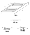
- FIG. 5 is a perspective view of the apparatus shown in FIG. 1 illustrating the location of the vibrating elements relative to the display;
- FIGS. 6A-6C illustrate movements associated with a piezoelectric member
- FIG. 7 is a graph illustrating voltage from a piezoelectric member under the display experiencing a touch mechanical stress
- FIG. 8 is a graph illustrating voltage from the piezoelectric members under the display shown in FIG. 5 experiencing a touch mechanical stress
- FIG. 9 is diagram illustrating a use case of touching the display of the apparatus shown in FIGS. 1 and 5 ;
- FIG. 10 is a graph illustrating voltages from a piezoelectric members under the display corresponding to the touch indicated in FIG. 9 ;
- FIG. 11 is diagram illustrating a use case of touching an alternate example display having four piezoelectric members
- FIG. 12 is a graph illustrating a voltage from a piezoelectric member under a display corresponding to a touch and release using two different size forces
- FIG. 13 is a diagram illustrating a first type of method of using the voltage(s) from the piezoelectric members
- FIG. 14 is a diagram illustrating a second type of method of using the voltage(s) from the piezoelectric members
- FIG. 15 is a diagram illustrating a third type of method of using the voltage(s) from the piezoelectric members
- FIG. 16 is a diagram illustrating a fourth type of method of using a voltage from a piezoelectric members
- FIG. 17 is a diagram of the apparatus shown in FIGS. 1 and 5 indicating a location for a user to touch for a boot-up process after an additional user interface (UI) item is pressed;
- UI user interface
- FIG. 18 is a diagram of the apparatus shown in FIGS. 1 and 5 indicating a motion for a user to copy by touch on the display for a boot-up process after an additional user interface (UI) item is pressed;
- UI user interface
- FIG. 19 is a chart of an example method
- FIG. 20 is a diagram of the apparatus shown in FIGS. 1 and 5 illustrating a motion of a finger on the display which may be used to unlock the apparatus;
- FIG. 21 is a diagram of the apparatus shown in FIGS. 1 and 5 to illustrate using the display module as an input without powering the capacitive touch sensor;
- FIG. 22 is a diagram illustrating voltages with different resistances.
- FIG. 1 there is shown a front view of an apparatus 10 incorporating features of an example embodiment.
- an apparatus 10 incorporating features of an example embodiment.
- the features will be described with reference to the example embodiments shown in the drawings, it should be understood that features can be embodied in many alternate forms of embodiments.
- any suitable size, shape or type of elements or materials could be used.
- the apparatus 10 is a hand-held communications device which includes a telephone application. In an alternate example the apparatus might not comprise a telephone application. In the example shown in FIG. 1 , the apparatus 10 may also comprise an Internet browser application, camera application, video recorder application, music player and recorder application, email application, navigation application, gaming application, and/or any other suitable electronic device application, such as may be provided on a smartphone or tablet computer for example. Referring to both FIGS. 1 and 2 , the apparatus 10 , in this example embodiment, comprises a housing 12 , a display module 14 , a receiver 16 , a transmitter 18 , a rechargeable battery 26 , and a controller 20 which may include at least one processor 22 , at least one memory 24 , and software 28 . However, all of these features are not necessary to implement the features described below. For example, features as described herein may be used in a non-portable apparatus which does not have a battery.
- the receiver 16 and transmitter 18 form a wireless mobile communication interface to allow the apparatus 10 to communicate with a wireless telephone system, such as a mobile telephone base station for example.
- the wireless mobile communication interface 16 , 18 may allow the apparatus 10 to communicate such as by 4G, 4G LTE, 3G, CDMA, etc. for example.
- the receiver 16 and transmitter 18 might not be provided, such as when the apparatus 10 does not have telephone capabilities.
- the apparatus 10 might merely be a gaming device or a music/video player.
- cellular circuit switched telephony or VoIP may be provided for example. So, a cellular system transmitter and receiver are not necessarily needed, such as if the device has only VoIP call functionality.
- the device may have a transmitter and a receiver for Wi-Fi.
- Internet access for the apparatus 10 might be provided by a short range communications system through a television console or a wireless WLAN for example. These are only some examples, and should not be considered as limiting.
- the display module 14 forms a speaker 70 comprising a vibrating element 72 and a display element 74 .
- the display element 74 in this example, is a touch screen display which functions as both a display screen and as a user input.
- the display element 74 may comprise a touch input device (TID) 30 , such as a capacitive sensor 31 for example (see FIG. 1 ).
- TID touch input device
- features described herein may be used in a display which does not have a capacitive touch sensor.
- another example may comprise an apparatus which has a touchpad or touch-panel which is not part of an electronic display screen.
- the electronic circuitry inside the housing 12 may comprise a printed wiring board (PWB) having components such as the controller 20 thereon.
- the circuitry may include a sound transducer provided as a microphone.
- the vibrating element 72 comprises at least one piezoelectric member 75 connected to a printed circuit board 76 .
- Piezoelectric material may be on either one, or both sides of a carrier plate.
- the display element 74 is an electronic display.
- a member 78 connects the piezoelectric member 75 to the back side of the display element 74 .
- the piezoelectric member 75 is flexed by the printed circuit board 76 . This causes the piezoelectric member 75 to move the electronic display 74 in and out as illustrated by arrow 634 to generate sound waves from the front of the electronic display 74 .
- the apparatus comprises two of the piezoelectric members 75 connected to the back side of the display element 74 .
- the piezo actuators may be directly coupled to the display module or might not be directly coupled to the display module.
- the speaker in a broader definition may comprise additional element(s).
- a speaker may have a plate under the display module where the piezos may be used to actuate the plate so that the plate could move/vibrate the display in a z-direction ( 634 ).
- a window plate 80 may be provided on the front face of the display element 74 .
- the vibrating element may comprise vibrating of the display with a dynamic actuator such as speaker or vibra.
- At least one piezo actuator may be suitably coupled to the display module for sound generation so that the display module can be used as a conventional display, but further for sound generation and perhaps tactile feedback.
- the piezo actuator may be coupled to the display window (in front of the display module) for sound generation. There are various ways of reproducing sound waves in the direction of the display module.
- the audio display module 14 is configured to function as a display and also function as a speaker or sound transducer.
- the audio display module 14 is connected to the controller 16 .
- the controller 16 is configured to control display of images on the display element 74 , and also control generation of sound from the audio display module 14 .
- the source of the images and sounds may comprise any suitable source(s), such as applications, video, data from the Internet, television signals, etc.
- the audio signals sent to the audio display module 14 may be formed or controlled by the controller.
- the audio signals may be telephone voice signals from a telephone conversation.
- the audio display module 14 is configured to provide an electronic display feature, an audio speaker feature and a haptic feedback feature.
- the haptic feedback feature might not be provided in an alternate embodiment. In another alternate example the haptic feedback feature might be provided without the display module 14 providing an audio speaker feature.
- the panel speaker concept is able to drive the display stack with actuators under the stack to produce localized haptics and also audio.
- the actuators are connected to the display usually from the middle and to the device frame usually from the ends, or visa versa.
- the used actuator may be a piezoelectric, such as a piezoceramic for example, which will deform when electric field is applied to it. In conjunction with non-piezoelectric material, the piezo will bend and thus it works as an actuator. Respectively, electric charge accumulates in the piezo in response to applied mechanical stress such as bending.
- FIG. 6A illustrates a piezoelectric member 75 in a home position.
- FIG. 6B illustrates the piezoelectric member 75 when mechanical stress is applied.
- FIG. 6C illustrates the piezoelectric member 75 when a voltage is applied. This may be used for haptic feedback and/or audio from the display 74 for example.
- FIG. 6B also corresponds to when a voltage is applied opposite to that as shown in FIG. 6C .
- Features as described herein may use two or more piezoelectric actuators under the display to detect touch location and force on the display, detect the movement of an object (such as a finger for example) on the display, and recognize movement patterns on the display.
- piezos can create electric charge as a result of mechanical stress, that feature can be used to trigger some functionality in the apparatus 10 , such as waking a CPU that is in sleep mode for example. As a result of that, this mechanism can be used instead of a separately powered touch sensor, at least in some use cases, resulting in better power efficiency.
- the piezos used may be provided primarily for other purpose(s) such as for providing haptics and/or audio.
- features as described herein may use piezos which are already in the apparatus and available for use.
- FIG. 7 shows a graph of voltage as a function of time in one of the piezoelectric actuators 75 when the apparatus is touched using a “normal” touch UI force by a user's finger for example.
- the voltage level is so high that it can be easily measured when the finger touches the display ( 32 on the left).
- One square means 200 mV in this graph. Lifting the finger from the display can be measured as well ( 34 on the right). These measurements were with a 10 kOhm load resistance connected to the piezo, and voltage was measured with an oscilloscope in AC coupling mode.
- FIG. 8 shows voltage as a function of time for the two piezoelectric actuators 75 when touched using a “normal” touch UI force over the other piezo.
- the voltage difference between the piezos is so high that it can be easily measured.
- Line 36 a is for the first piezoelectric actuator shown in FIGS. 4-5 and line 36 b is for the second piezoelectric actuator shown in FIGS. 4-5 .
- the finger touched the display closer to the first piezo than the second piezo.
- the curve 36 a is the voltage of the first, closer piezo
- the curve 36 b is the voltage of the second, farther piezo.
- the voltage difference between the piezos is so high that it can be easily measured that the finger lifting from the display (as indicated by 34 ) was closer to the first piezo than the second piezo.
- FIG. 9 shows when the display of the apparatus 10 is touched using a “normal” touch UI force over the first piezo 75 a , then the finger was moved towards the second piezo 75 b . The finger is touching the display during the movement, and then the finger is lifted from the display near the second piezo 75 b .
- T stands for touch
- L stands for lift.
- FIG. 10 shows the voltages as a function of time in the two piezoelectric actuators during the touch T, movement and subsequent lift L of FIG. 9 .
- the apparatus may be able to recognize the gesture T-L on the display shown in FIG. 9 via the signals shown in FIG. 10 and perform a predetermined function based upon that recognized gesture.
- FIG. 11 shows a concept of the apparatus 10 where there are four piezos 75 a - 75 b under the display 74 . All of the piezos are connected to the display 74 from the middle and to the housing 12 from the ends. With this mechanism, movement of the finger on the device's x-axis can also be measured.
- piezo 75 a provides the highest voltage.
- the relative voltage between the piezos changes. The same happens when the finger is moved towards the top and right side of the device.
- the apparatus may be able to recognize the gesture T-L shown in FIG. 11 on the touchscreen display 74 which is otherwise OFF, and perform a predetermined function based upon that recognized gesture.
- FIG. 12 shows the voltage as a function of time when the apparatus 10 is touched using first a “normal” touch UI force 32 and then released 34 , and then touched again 32 ′ using more force and then released 34 ′.
- one approach is to provide the apparatus 10 with an application-specific integrated circuit (ASIC) 40 designed for the purpose that wakes up when a certain voltage has been reached in any of the four piezos shown.
- ASIC application-specific integrated circuit
- FIGS. 13-15 work equally well with the apparatus 10 having only two piezos. That ASIC 40 may then be used to wake up the main processor 22 and pass the voltage values to the main processor 22 for further processing.
- ASIC 40 ′ designed for this purpose that wakes up when a predetermined voltage has been reached in any of the piezos. That ASIC 40 ′ may then wake up the main processor 22 , analyze the voltages and pass the touch coordinates to the main processor (x, y, z) for further processing.
- the ASIC may have a programmable CPU and memory so that it can adapt to different manufacturing device sizes and shapes and piezo positions.
- a third approach is that there is an ASIC 40 ′′ designed for this purpose that wakes up when certain voltage has been reached in any of the piezos. That ASIC may then wake up the main processor 22 , analyze the voltages over time, detect a gesture made with the finger, and pass that gesture ID to the main processor.
- One example gesture is shown in FIG. 11 .
- the ASIC may have a programmable CPU and memory so that it can detect multiple gestures.
- a fourth approach is that the voltage threshold detector may provide a trigger (e.g. an interrupt) in the main processor 22 that then starts reading the voltage values directly from the piezos.
- FIG. 16 shows a simplified example that uses just one piezo.
- a swipe as described in FIG. 9 could result in decreasing music volume (by one step or by multiple steps depending on the length of the swipe). This would be practical, for example, when the user is jogging and wants to adjust the volume of the apparatus in a pocket.
- These features allow an apparatus to be provided without side volume keys, such as if volume can be adjusted from the display when display is switched ON, or using locked-swipe when the display switched OFF. Similar logic could be used for telephony audio volume control when the device is unlocked.
- Another example use case is swiping sideways to result in playing a clock time to headphones or loudspeaker using text-to-speech.
- a person who is jogging does not have to look at the display, but would hear the clock time.
- Another example use case is swiping sideways for changing a FM radio station to a next one when playing to headphones and the device is locked.
- Another example use case is that a certain gesture (e.g. drawing a circle) on the display could result in unlocking the device.
- a certain gesture e.g. drawing a circle
- force detection may be used while the display is OFF.
- the Tactile Audio Display construction has a floating display stack, it can be used as a button.
- the piezos may be used as a power button while the display 74 is OFF.
- a separate ASIC 40 may be started up and then wake up and start a normal boot-up process.
- the display and window may be rigidly connected to phone mechanics.
- the apparatus may be configured such that the actual boot-up process may start only after an additional user interface (UI) item 50 is pressed (requires touch and display to work) as in FIG. 17 or an additional gesture 52 is done (requires touch to work) as in FIG. 18 .
- UI user interface
- the apparatus may be configured such that the actual boot-up process may start only after an additional user interface (UI) item 50 is pressed (requires touch and display to work) as in FIG. 17 or an additional gesture 52 is done (requires touch to work) as in FIG. 18 .
- UI user interface
- the boot-up can be also done as a series of presses. For example, long strong press initiates the process and an additional double tap (detected using the piezos or accelerometer) would then result in the actual start of the boot-up process. This use case is not limited to any specific gesture or frequency of taps.
- FIG. 19 shows an example of an overall process and includes the shutdown and the UI for that.
- the ASIC works as described in FIG. 15 with the addition that it can send a boot-up signal to main processor.
- FIG. 21 shows an example where the user could move his/her character 42 in the dungeon by tapping different parts of the display 74 . There is no need to enable the touch sensor 31 that consumes power since the zero-power non-capacitive touch using the piezos can do that instead.
- Another example of game control would be a minigolf game where the strength of the press may signal the power of the putt and the location of the touch indicates the direction of the putt.
- FIG. 22 shows two graphs. 44 illustrates the voltage measured using the 10 kOhm resistor and 45 illustrates the voltage using the oscilloscope's internal resistor which is higher than 100 kOhm. With higher impedance, the static force can be measured over much longer period of time. All the use cases can be implemented using a smaller impedance as described above, although only the changes can be reliably detected.
- piezoelectric actuators under the display (Tactile Audio Display construction) to detect touch location and touch force on the display. This may include utilizing the knowledge of the touch information to conclude UI gestures. This may include utilizing the force sensing provided by piezos to use the display stack as a button and, more specifically, as an apparatus ON power button. Since the piezos can create electric charge, this solution may be used as a zero-power touch sensor. In some use cases this may replace utilizing the touch sensor 31 .
- One good example use case is when the device is locked and display (including the touch sensor 31 ) is switched OFF.
- Features may be used to provide touch detection without any power consumption from the touch sensor.
- Features may be used to utilizing the display stack as a button (such as a power button for example).
- Features may be used to provide two or more piezoelectric actuators under the display to detect touch location and force on the display, detect the movement of an object on the display, and recognize movement patterns on the display.
- piezos can create electric charge as a result of mechanical stress
- that feature can be used to trigger some functionality in the device.
- the functionality may comprise waking a CPU that is in sleep mode.
- this mechanism can be used instead the touch sensor 31 at least in some use cases resulting in better power efficiency for the apparatus 10 .
- This may provide a functional alternative for touch sensor 31 that does not use any power, because the construction itself produces electric charge. This enables the display stack to be used as a button without a need for a physical button.
- An example embodiment may be provided comprising a display; and at least one piezoelectric member connected to the display, where the at least one piezoelectric member is configured to move the display, where, when the display is pressed to mechanically stress the at least one piezoelectric member, the apparatus is configured to: wake up the apparatus from a sleep mode based upon electricity from the at least one piezoelectric member, and/or determine a location where the display was pressed based upon respective signals from at least two of the piezoelectric members, and/or determine a force and/or impulse applied from a voltage measured from the at least one piezoelectric member.
- the display may be an electronic display which is part of a panel speaker formed by the display and the at least one piezoelectric member.
- the at least one piezoelectric member may be connected to circuitry of the apparatus to supply the electricity to the circuitry, and where the circuitry is configured to wake up a processor of the apparatus based upon receiving a predetermined voltage from the at least one piezoelectric member.
- the circuitry may be configured to supply a voltage value to the processor for processing.
- the circuitry may be configured to analyze the voltage(s) from the at least one piezoelectric member and signal the processor of coordinates where the display was pressed.
- the circuitry may be configured to analyze the voltages from the at least two piezoelectric members over time, determine a gesture as the press moves on the display, and signal a gesture identification to the processor.
- the circuitry may be configured to send a trigger signal to the processor to wake up the processor, and the processor is configured to read the voltage(s) directly from the at least one piezoelectric member.
- the display may comprise a touch input device (TID) comprising a touch sensor, where the apparatus is configured to wake up the apparatus from the sleep mode and/or determine the location where the display was pressed when the touch input device is not powered.
- TID touch input device
- the apparatus may comprise at least one processor, and at least one memory having software, where the processor(s), the memory(ies) and the software are configured to perform a predetermined function based upon the touch input device not being powered and a predetermined pressing motion along the display being determined based upon the respective signals from the at least two piezoelectric members.
- the apparatus may be configured to wake up the apparatus from the sleep mode, based upon the electricity from the at least one piezoelectric member, when within a predetermined time of the display being pressed: an additional user input item is actuated, and/or a predetermined touch gesture along the display is determined.
- the display may comprise a touch input device (TID) comprising a touch sensor, where a state of the apparatus is configured to be changed from locked to unlocked, while the touch input device is not powered, by a predetermined touch gesture along the display being determined from the respective signals from the at least two piezoelectric members.
- the display may comprise a touch input device (TID) comprising a touch sensor, where the apparatus is configured to operate an application, while the touch input device is not powered, with input signals to the application from the at least one piezoelectric member generated by a user pressing on the display and sending the input signals from the at least one piezoelectric member based upon the pressing.
- the apparatus may further comprise a battery, at least one printed wiring board including a transmitter and a receiver, at least one processor, and at least one memory comprising software, where the software comprises a telephone application.
- An example method may comprise pressing a display of an apparatus to mechanically stress at least one piezoelectric member connected to the display; and generating electricity from the at least one piezoelectric member from the mechanical stress to: wake up the apparatus from a sleep mode, and/or determine a location where the display was pressed based upon the respective electricity from at least two of the piezoelectric members.
- the at least one piezoelectric member may be connected to circuitry of the apparatus to supply the electricity to the circuitry, where the circuitry wakes up a processor of the apparatus based upon receiving a predetermined voltage from the at least one piezoelectric member, where: based upon receiving the predetermined voltage from the at least one piezoelectric member, the circuitry supplies a voltage value to the processor for processing, and/or the circuitry analyzes the voltage(s) from the at least one piezoelectric member and signals the processor of coordinates where the display was pressed, and/or the circuitry analyzes the voltages from the at least two piezoelectric members over time, and determines a gesture as the press moves on the display, and signals a gesture identification to the processor, and/or the circuitry sends a trigger signal to the processor to wake up the processor, and the processor directly reads the voltage(s) from the at least one piezoelectric member.
- the display may comprise a touch input device (TID) comprising a touch sensor, where the apparatus wakes up the apparatus from the sleep mode and/or determines the location where the display was pressed when the touch input device is not powered.
- TID touch input device
- the apparatus may comprise at least one processor, and at least one memory having software, where the processor(s), the memory(ies) and the software perform a predetermined function based upon the touch input device not being powered and a predetermined pressing motion along the display being determined.
- the apparatus may wake up from the sleep mode, based upon the electricity from the at least one piezoelectric member, when within a predetermined time of the display being pressed: an additional user input item is actuated, and/or a predetermined touch gesture along the display is determined.
- the display may comprise a touch input device (TID) comprising a touch sensor: where a state of the apparatus is changed from locked to unlocked, while the touch input device is not powered, by a predetermined touch gesture along the display being determined from the respective signals from the at least two piezoelectric members, and/or where the apparatus operates an application, while the touch input device is not powered, with input signals to the application from the at least one piezoelectric member generated by a user pressing on the display and sending the input signals from the at least one piezoelectric member based upon the pressing.
- TID touch input device
- a non-transitory program storage device such as memory 24 for example, readable by a machine, tangibly embodying a program of instructions executable by the machine for performing operations may be provided, the operations comprising: waking up an apparatus from a sleep mode based upon electricity from the at least one piezoelectric member which has been mechanically stressed to generate the electricity from pressing of a display of the apparatus connected to the at least one piezoelectric member, and/or determining a location where the display was pressed based upon respective electricity from at least two of the piezoelectric members generated by the pressing of the display.
Priority Applications (4)
| Application Number | Priority Date | Filing Date | Title |
|---|---|---|---|
| US13/943,914 US9213434B2 (en) | 2013-07-17 | 2013-07-17 | Piezoelectric actuator and method |
| CN201480048562.1A CN105518591A (zh) | 2013-07-17 | 2014-05-21 | 压电致动器和方法 |
| PCT/FI2014/050386 WO2015007944A1 (en) | 2013-07-17 | 2014-05-21 | Piezoelectric actuator and method |
| EP14826398.1A EP3022632A4 (en) | 2013-07-17 | 2014-05-21 | Piezoelectric actuator and method |
Applications Claiming Priority (1)
| Application Number | Priority Date | Filing Date | Title |
|---|---|---|---|
| US13/943,914 US9213434B2 (en) | 2013-07-17 | 2013-07-17 | Piezoelectric actuator and method |
Publications (2)
| Publication Number | Publication Date |
|---|---|
| US20150022459A1 US20150022459A1 (en) | 2015-01-22 |
| US9213434B2 true US9213434B2 (en) | 2015-12-15 |
Family
ID=52343183
Family Applications (1)
| Application Number | Title | Priority Date | Filing Date |
|---|---|---|---|
| US13/943,914 Active 2033-11-26 US9213434B2 (en) | 2013-07-17 | 2013-07-17 | Piezoelectric actuator and method |
Country Status (4)
| Country | Link |
|---|---|
| US (1) | US9213434B2 (zh) |
| EP (1) | EP3022632A4 (zh) |
| CN (1) | CN105518591A (zh) |
| WO (1) | WO2015007944A1 (zh) |
Cited By (3)
| Publication number | Priority date | Publication date | Assignee | Title |
|---|---|---|---|---|
| US10254884B2 (en) | 2016-11-21 | 2019-04-09 | Qualcomm Incorporated | Apparatus for piezoelectric force detection |
| US20190265793A1 (en) * | 2018-02-28 | 2019-08-29 | Google Llc | Piezoelectric haptic feedback module |
| US10986446B2 (en) * | 2017-02-24 | 2021-04-20 | Google Llc | Panel loudspeaker controller and a panel loudspeaker |
Families Citing this family (13)
| Publication number | Priority date | Publication date | Assignee | Title |
|---|---|---|---|---|
| JP2015002428A (ja) * | 2013-06-14 | 2015-01-05 | 富士通株式会社 | 携帯端末装置、機能制御方法および機能制御プログラム |
| KR20160014481A (ko) * | 2014-07-29 | 2016-02-11 | 삼성전자주식회사 | Idle 모드에서 동작하는 전자 장치 및 방법 |
| WO2016106481A1 (en) * | 2014-12-29 | 2016-07-07 | Empire Technology Development Llc | Quick command entry for wearable devices |
| CN105278671A (zh) * | 2015-01-31 | 2016-01-27 | 维沃移动通信有限公司 | 移动终端的控制方法及移动终端 |
| KR102496410B1 (ko) * | 2016-03-25 | 2023-02-06 | 삼성전자 주식회사 | 전자 장치 및 전자 장치의 소리 출력 방법 |
| WO2017212028A1 (en) * | 2016-06-09 | 2017-12-14 | Aito Bv | Detection of piezoelectric sensor elements |
| US10206044B2 (en) | 2016-09-08 | 2019-02-12 | Microsoft Technology Licensing, Llc | Display structure having a visual display and an audio output |
| KR20180090589A (ko) * | 2017-02-03 | 2018-08-13 | 엘지전자 주식회사 | 이동 단말기 및 이의 제어방법 |
| JP2018133021A (ja) * | 2017-02-17 | 2018-08-23 | 富士通コンポーネント株式会社 | 触感提示装置及びタッチパネル |
| FI20195169A1 (en) * | 2019-03-07 | 2020-09-08 | Aito Bv | Apparatus and method for detecting contact |
| US11379081B2 (en) * | 2020-08-17 | 2022-07-05 | Dynascan Technology Corp. | Touch system and method of operating the same |
| FI20215120A1 (en) | 2021-02-04 | 2022-08-05 | Aito Bv | Piezoelectric sensor device |
| CN113844360A (zh) * | 2021-09-03 | 2021-12-28 | 上海博泰悦臻电子设备制造有限公司 | 车载人机交互系统 |
Citations (20)
| Publication number | Priority date | Publication date | Assignee | Title |
|---|---|---|---|---|
| US6492979B1 (en) | 1999-09-07 | 2002-12-10 | Elo Touchsystems, Inc. | Dual sensor touchscreen utilizing projective-capacitive and force touch sensors |
| US20050078093A1 (en) | 2003-10-10 | 2005-04-14 | Peterson Richard A. | Wake-on-touch for vibration sensing touch input devices |
| US20060140439A1 (en) | 2004-12-27 | 2006-06-29 | Takahiro Nakagawa | Gasket member, diaphragm, flat panel speaker, method of mounting same flat panel speaker, and method of assembling electronic device |
| US20080055277A1 (en) | 2006-08-29 | 2008-03-06 | Sony Corporation | Touch panel display, electronic apparatus and playing apparatus |
| EP2026173A1 (en) | 2007-08-13 | 2009-02-18 | Research In Motion Limited | Touchscreen for electronic device |
| US20090176534A1 (en) * | 2008-01-08 | 2009-07-09 | Lee Eun Hwa | Mobile terminal having flat panel sound output unit and vibration generation method for the same |
| US20100090564A1 (en) * | 2008-10-09 | 2010-04-15 | Samsung Electronics Co., Ltd. | Method and apparatus for unlocking a portable terminal using piezoelectric sensors |
| US20100225600A1 (en) | 2009-03-09 | 2010-09-09 | Motorola Inc. | Display Structure with Direct Piezoelectric Actuation |
| US7890778B2 (en) | 2007-01-06 | 2011-02-15 | Apple Inc. | Power-off methods for portable electronic devices |
| EP2315101A1 (en) | 2009-10-02 | 2011-04-27 | Research In Motion Limited | A method of waking up and a portable electronic device configured to perform the same |
| US20110261021A1 (en) | 2010-04-23 | 2011-10-27 | Immersion Corporation | Transparent composite piezoelectric combined touch sensor and haptic actuator |
| US20110279382A1 (en) | 2010-05-14 | 2011-11-17 | Research In Motion Limited | Electronic device including tactile touch-sensitive display and method of controlling same |
| WO2012025783A1 (en) | 2010-08-23 | 2012-03-01 | Nokia Corporation | Apparatus and method for providing haptic and audio feedback in a touch sensitive user interface. |
| WO2012052803A1 (en) | 2010-10-19 | 2012-04-26 | Nokia Corporation | A display apparatus |
| WO2012090031A1 (en) | 2010-12-31 | 2012-07-05 | Nokia Corporation | A display apparatus producing audio and haptic output |
| EP2479642A1 (en) | 2011-01-21 | 2012-07-25 | Research In Motion Limited | System and method for reducing power consumption in an electronic device having a touch-sensitive display |
| EP2492782A1 (en) | 2011-02-28 | 2012-08-29 | Research In Motion Limited | Patterned activation of piezoelectric actuators |
| WO2012114754A1 (ja) | 2011-02-24 | 2012-08-30 | 京セラ株式会社 | 電子機器 |
| WO2012129247A2 (en) | 2011-03-21 | 2012-09-27 | Apple Inc. | Electronic devices with flexible displays |
| US20130227495A1 (en) * | 2012-02-24 | 2013-08-29 | Daniel Tobias RYDENHAG | Electronic device and method of controlling a display |
Family Cites Families (5)
| Publication number | Priority date | Publication date | Assignee | Title |
|---|---|---|---|---|
| GB2357400A (en) * | 1999-12-17 | 2001-06-20 | Nokia Mobile Phones Ltd | Controlling a terminal of a communication system |
| EP2315102B1 (en) * | 2009-10-02 | 2018-01-31 | BlackBerry Limited | A low power wakeup detection circuit and a portable electronic device having a low power wakeup detection circuit |
| US8633916B2 (en) * | 2009-12-10 | 2014-01-21 | Apple, Inc. | Touch pad with force sensors and actuator feedback |
| US8432368B2 (en) * | 2010-01-06 | 2013-04-30 | Qualcomm Incorporated | User interface methods and systems for providing force-sensitive input |
| US8934228B2 (en) * | 2011-03-21 | 2015-01-13 | Apple Inc. | Display-based speaker structures for electronic devices |
-
2013
- 2013-07-17 US US13/943,914 patent/US9213434B2/en active Active
-
2014
- 2014-05-21 CN CN201480048562.1A patent/CN105518591A/zh active Pending
- 2014-05-21 EP EP14826398.1A patent/EP3022632A4/en not_active Ceased
- 2014-05-21 WO PCT/FI2014/050386 patent/WO2015007944A1/en active Application Filing
Patent Citations (21)
| Publication number | Priority date | Publication date | Assignee | Title |
|---|---|---|---|---|
| US6492979B1 (en) | 1999-09-07 | 2002-12-10 | Elo Touchsystems, Inc. | Dual sensor touchscreen utilizing projective-capacitive and force touch sensors |
| US20050078093A1 (en) | 2003-10-10 | 2005-04-14 | Peterson Richard A. | Wake-on-touch for vibration sensing touch input devices |
| US20060140439A1 (en) | 2004-12-27 | 2006-06-29 | Takahiro Nakagawa | Gasket member, diaphragm, flat panel speaker, method of mounting same flat panel speaker, and method of assembling electronic device |
| US20080055277A1 (en) | 2006-08-29 | 2008-03-06 | Sony Corporation | Touch panel display, electronic apparatus and playing apparatus |
| US7890778B2 (en) | 2007-01-06 | 2011-02-15 | Apple Inc. | Power-off methods for portable electronic devices |
| EP2026173A1 (en) | 2007-08-13 | 2009-02-18 | Research In Motion Limited | Touchscreen for electronic device |
| US20090176534A1 (en) * | 2008-01-08 | 2009-07-09 | Lee Eun Hwa | Mobile terminal having flat panel sound output unit and vibration generation method for the same |
| US20100090564A1 (en) * | 2008-10-09 | 2010-04-15 | Samsung Electronics Co., Ltd. | Method and apparatus for unlocking a portable terminal using piezoelectric sensors |
| US20100225600A1 (en) | 2009-03-09 | 2010-09-09 | Motorola Inc. | Display Structure with Direct Piezoelectric Actuation |
| EP2315101A1 (en) | 2009-10-02 | 2011-04-27 | Research In Motion Limited | A method of waking up and a portable electronic device configured to perform the same |
| US20110261021A1 (en) | 2010-04-23 | 2011-10-27 | Immersion Corporation | Transparent composite piezoelectric combined touch sensor and haptic actuator |
| US20110279382A1 (en) | 2010-05-14 | 2011-11-17 | Research In Motion Limited | Electronic device including tactile touch-sensitive display and method of controlling same |
| WO2012025783A1 (en) | 2010-08-23 | 2012-03-01 | Nokia Corporation | Apparatus and method for providing haptic and audio feedback in a touch sensitive user interface. |
| WO2012052803A1 (en) | 2010-10-19 | 2012-04-26 | Nokia Corporation | A display apparatus |
| WO2012090031A1 (en) | 2010-12-31 | 2012-07-05 | Nokia Corporation | A display apparatus producing audio and haptic output |
| EP2479642A1 (en) | 2011-01-21 | 2012-07-25 | Research In Motion Limited | System and method for reducing power consumption in an electronic device having a touch-sensitive display |
| WO2012114754A1 (ja) | 2011-02-24 | 2012-08-30 | 京セラ株式会社 | 電子機器 |
| US20130335211A1 (en) | 2011-02-24 | 2013-12-19 | Kyocera Corporation | Electronic device |
| EP2492782A1 (en) | 2011-02-28 | 2012-08-29 | Research In Motion Limited | Patterned activation of piezoelectric actuators |
| WO2012129247A2 (en) | 2011-03-21 | 2012-09-27 | Apple Inc. | Electronic devices with flexible displays |
| US20130227495A1 (en) * | 2012-02-24 | 2013-08-29 | Daniel Tobias RYDENHAG | Electronic device and method of controlling a display |
Non-Patent Citations (1)
| Title |
|---|
| Patently Apple; "Apple Looking to deliver a little More Buzz to iOS Devices"; Mar. 22, 2012; whole document (7 pages); Retrieved from the Internet at http://www.patentlyapple.com/patently-apple/2012/03/apple-looking-to-deliver-a-little-more-buzz-to-ios-devices.html. |
Cited By (4)
| Publication number | Priority date | Publication date | Assignee | Title |
|---|---|---|---|---|
| US10254884B2 (en) | 2016-11-21 | 2019-04-09 | Qualcomm Incorporated | Apparatus for piezoelectric force detection |
| US10986446B2 (en) * | 2017-02-24 | 2021-04-20 | Google Llc | Panel loudspeaker controller and a panel loudspeaker |
| US20190265793A1 (en) * | 2018-02-28 | 2019-08-29 | Google Llc | Piezoelectric haptic feedback module |
| US10996755B2 (en) * | 2018-02-28 | 2021-05-04 | Google Llc | Piezoelectric haptic feedback module |
Also Published As
| Publication number | Publication date |
|---|---|
| EP3022632A1 (en) | 2016-05-25 |
| US20150022459A1 (en) | 2015-01-22 |
| WO2015007944A1 (en) | 2015-01-22 |
| CN105518591A (zh) | 2016-04-20 |
| EP3022632A4 (en) | 2017-02-15 |
Similar Documents
| Publication | Publication Date | Title |
|---|---|---|
| US9213434B2 (en) | Piezoelectric actuator and method | |
| AU2018282404B2 (en) | Touch-sensitive button | |
| EP2802974B1 (en) | Touch screen device with surface switch | |
| US9417696B2 (en) | Portable electronic device and method therefor | |
| US9189099B2 (en) | Information input unit, information input method, and computer program | |
| KR20150049312A (ko) | 촉각 피드백을 제공하기 위한 전자 장치, 스타일러스 펜 및 방법 | |
| KR20150073747A (ko) | 햅틱 피드백을 제공하기 위한 방법, 시스템 및 컴퓨터 판독 가능한 기록 매체. | |
| US20110128236A1 (en) | Electronic device and method of controlling same | |
| EP2482164B1 (en) | Portable electronic device and method therefor | |
| KR20220145383A (ko) | 회로 제어 장치 및 방법 | |
| JP6096854B1 (ja) | 電子機器及び電子機器の動作方法 | |
| KR20120115159A (ko) | 택타일 피드백 방법 및 장치 | |
| JP6786245B2 (ja) | 情報処理装置 | |
| JP7329150B2 (ja) | タッチボタン、制御方法及び電子機器 | |
| JP2018502486A (ja) | 端末の制御装置及びこれを用いた端末の制御方法 | |
| JP6488081B2 (ja) | 表示画面を備えた端末装置を用いた周囲雑音による注意散漫の低減 | |
| JP2018014111A (ja) | 電子機器 | |
| EP2763006A1 (en) | Electronic device including touch-sensitive display and method of detecting touches | |
| EP2328065A1 (en) | Electronic device and method of controlling same | |
| KR20100059342A (ko) | 휴대 단말기의 터치 입력 장치 및 그의 구동 방법 | |
| JP2017069990A (ja) | 電子機器 | |
| CA2841330A1 (en) | Electronic device including touch-sensitive display and method of detecting touches | |
| KR20130016788A (ko) | 단말 및 그 단말에서 슬라이드 입력 감지 방법 |
Legal Events
| Date | Code | Title | Description |
|---|---|---|---|
| AS | Assignment |
Owner name: NOKIA CORPORATION, FINLAND Free format text: ASSIGNMENT OF ASSIGNORS INTEREST;ASSIGNORS:YLIAHO, MARKO TAPANI;KEMPPINEN, PASI TUOMO ANTERO;PAAAHO, JOUNI ASLAK;SIGNING DATES FROM 20130711 TO 20130712;REEL/FRAME:030813/0914 |
|
| AS | Assignment |
Owner name: NOKIA TECHNOLOGIES OY, FINLAND Free format text: ASSIGNMENT OF ASSIGNORS INTEREST;ASSIGNOR:NOKIA CORPORATION;REEL/FRAME:034781/0200 Effective date: 20150116 |
|
| STCF | Information on status: patent grant |
Free format text: PATENTED CASE |
|
| MAFP | Maintenance fee payment |
Free format text: PAYMENT OF MAINTENANCE FEE, 4TH YEAR, LARGE ENTITY (ORIGINAL EVENT CODE: M1551); ENTITY STATUS OF PATENT OWNER: LARGE ENTITY Year of fee payment: 4 |
|
| MAFP | Maintenance fee payment |
Free format text: PAYMENT OF MAINTENANCE FEE, 8TH YEAR, LARGE ENTITY (ORIGINAL EVENT CODE: M1552); ENTITY STATUS OF PATENT OWNER: LARGE ENTITY Year of fee payment: 8 |