US9190224B2 - Rotary switch with push function - Google Patents
Rotary switch with push function Download PDFInfo
- Publication number
- US9190224B2 US9190224B2 US13/983,333 US201213983333A US9190224B2 US 9190224 B2 US9190224 B2 US 9190224B2 US 201213983333 A US201213983333 A US 201213983333A US 9190224 B2 US9190224 B2 US 9190224B2
- Authority
- US
- United States
- Prior art keywords
- knob
- guide
- core
- switch assembly
- switch
- Prior art date
- Legal status (The legal status is an assumption and is not a legal conclusion. Google has not performed a legal analysis and makes no representation as to the accuracy of the status listed.)
- Active, expires
Links
- 238000005096 rolling process Methods 0.000 claims abstract description 17
- 230000033001 locomotion Effects 0.000 claims abstract description 15
- 230000001419 dependent effect Effects 0.000 claims abstract description 5
- 230000000007 visual effect Effects 0.000 claims description 3
- QHZSDTDMQZPUKC-UHFFFAOYSA-N 3,5-dichlorobiphenyl Chemical compound ClC1=CC(Cl)=CC(C=2C=CC=CC=2)=C1 QHZSDTDMQZPUKC-UHFFFAOYSA-N 0.000 description 8
- 230000000295 complement effect Effects 0.000 description 6
- 238000004519 manufacturing process Methods 0.000 description 4
- 238000000034 method Methods 0.000 description 4
- 239000000463 material Substances 0.000 description 3
- 230000001627 detrimental effect Effects 0.000 description 2
- 238000005286 illumination Methods 0.000 description 2
- 239000004973 liquid crystal related substance Substances 0.000 description 2
- 230000002093 peripheral effect Effects 0.000 description 2
- 230000036316 preload Effects 0.000 description 2
- 238000004026 adhesive bonding Methods 0.000 description 1
- 238000004378 air conditioning Methods 0.000 description 1
- 239000000470 constituent Substances 0.000 description 1
- 230000008602 contraction Effects 0.000 description 1
- 238000002788 crimping Methods 0.000 description 1
- 238000009434 installation Methods 0.000 description 1
- 239000000543 intermediate Substances 0.000 description 1
- 238000005304 joining Methods 0.000 description 1
- 238000004806 packaging method and process Methods 0.000 description 1
- 229920001296 polysiloxane Polymers 0.000 description 1
- 238000003825 pressing Methods 0.000 description 1
- 238000010200 validation analysis Methods 0.000 description 1
Images


Classifications
-
- H—ELECTRICITY
- H01—ELECTRIC ELEMENTS
- H01H—ELECTRIC SWITCHES; RELAYS; SELECTORS; EMERGENCY PROTECTIVE DEVICES
- H01H3/00—Mechanisms for operating contacts
- H01H3/02—Operating parts, i.e. for operating driving mechanism by a mechanical force external to the switch
- H01H3/08—Turn knobs
-
- H—ELECTRICITY
- H01—ELECTRIC ELEMENTS
- H01H—ELECTRIC SWITCHES; RELAYS; SELECTORS; EMERGENCY PROTECTIVE DEVICES
- H01H25/00—Switches with compound movement of handle or other operating part
- H01H25/06—Operating part movable both angularly and rectilinearly, the rectilinear movement being along the axis of angular movement
-
- H—ELECTRICITY
- H01—ELECTRIC ELEMENTS
- H01H—ELECTRIC SWITCHES; RELAYS; SELECTORS; EMERGENCY PROTECTIVE DEVICES
- H01H3/00—Mechanisms for operating contacts
- H01H3/02—Operating parts, i.e. for operating driving mechanism by a mechanical force external to the switch
- H01H3/12—Push-buttons
Definitions
- the present invention relates to a multifunctional switch with an indicator, in which a plurality of functions can be selected and validated through a rotation and a push of a dial knob.
- Rotary switch of the aforementioned type exists and are commonly implemented in automotive environment for instance to control the air conditioning or a Hi-Fi system.
- Said switches are typically built on an electronic printed circuit board (PCB).
- PCB electronic printed circuit board
- a tubular cylindrical core is fixed on the PCB, and serves as a primary guide for a bushing that is placed over said cylindrical core.
- An external rotary knob accessible to an operator, is placed over the bushing.
- the switch is in mechanical and electrical connection with the PCB and the rotation of the knob selects various functions.
- a function chosen by rotation can be validated by a push on the knob, which then axially slides on the bushing toward the PCB and commutes an electrical switch.
- An elastic mean such as a coil spring, biases the knob away from the pushed position, where a function has been validated, back to an extended position, when not pressed by the operator.
- a liquid crystal display may be fixed on the core while the knob remains open or provided with a transparent window in order to leave a visual direct access to the LCD.
- a back illumination of the LCD is made possible as the hollow center of the cylindrical core is a light channel for a light beam generated by a light source, typically a light-emitting diode (LED) fixed on the PCB.
- a light source typically a light-emitting diode (LED) fixed on the PCB.
- features of the present invention provide a switch assembly according to the characteristics' of claim 1 .
- the switch assembly comprises the coaxial assembly along a longitudinal axis of a cylindrical core, axially extending from a base to a distal end, the core-base being fixed to a base plate, an outer knob, extending from a knob-base to a distal knob-top, the knob being axially rotatable about the core, a switching mean generating an electrical signal dependent on the rotations of the knob, and a mean for guiding the knob in its motions relative to the core.
- Said mean comprises an upper-guide, in the vicinity of the core-end and the knob-top, and a lower-guide in the vicinity of the core-base and the knob-base.
- the upper-guide comprises rolling elements, said elements rolling between an upper-guide inner race integral to the core, and an upper-guide outer race integral to the knob. Thanks to this upper bearing arrangement, the rotations of the knob are advantageously friction-free.
- the outer race is truncated with upward apex and the switch assembly further comprises a mean for generating an upward axial force biasing the rolling elements onto the upper-guide outer race. This advantageously eliminates any free play that would be detrimental to the tactile feeling when operating the knob.
- the lower-guide may as well comprise rolling elements, said elements rolling between a lower-guide inner race integral to the core, and a lower-guide outer race integral to the knob.
- the lower-guide outer race is truncated with downward apex and the switch assembly further comprises a mean for generating a downward axial force biasing the rolling elements onto the lower-guide outer race. Thanks to this bearing-like arrangement for the lower guide symmetrical to the upper guide, undesirable friction is eliminated in the motion of the knob.
- the means for biasing the rolling elements are placed between the upper-guide and the lower-guide and are equally pushing apart said guides in opposite axial directions. This advantageously reduces the number of components by combining the means for biasing, in using a single mean that serves both purposes for the upper guide and for the lower guide.
- the switch assembly further comprises a mean for indexing the rotation of the knob.
- This mean comprises an indexing member biased by an elastic member against an indented path integral to the knob.
- the indexing member is linked to the base.
- a symmetrical mounting with the indented path integral to the base and the indexing member is linked the knob is possible. This advantageously keeps the knob in position when not operated.
- the knob is further able to axially translate relative to the core between a first position and a second position.
- the mean for guiding the knob in its motions relative to the core guides the knob when it translates.
- Another switching mean generating another electrical signal dependent on the translation of the knob is provided. This, for instance, enables to validate functions.
- the switch assembly further comprises another mean generating a unidirectional axial force onto the knob forcing said knob to return into the first position after being displaced from said first position. This keeps the knob in the first position when it is not operated.
- Said mean for generating a unidirectional axial force comprises the indented path and the indexing member. The indents of the indented path are operated in a groove having two symmetrical sides. In the first position, the indexing member is biased in the bottom of the groove generating on the knob symmetrical and balanced upward and downward forces. The knob is at equilibrium. When away from the first position, the indexing member travels on one side of the groove generating on the knob the unidirectional force that forces the knob to return to the first position.
- knob-top is open or provided with a transparent mean leaving visual access to a display, fixed on the core-end.
- the core is tubular and its the hollow center is a light channel for a light beam generated by a source. The light beam back illuminates the display.
- FIG. 1 is a perspective view of a switch assembly as per the invention
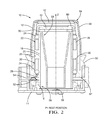
- FIG. 2 is a section of the switch of FIG. 1 , the section being in a vertical plan passing through rolling elements, the switch being in rest position;
- FIG. 3 is the same section as in FIG. 2 , the switch assembly being in pushed position;
- FIG. 4 is a section of the switch of FIG. 1 , the section being in a vertical plan passing through guiding elements, the switch being in rest position;
- FIG. 5 is the same section as in FIG. 4 , the switch assembly being in pushed position;
- FIG. 6 is a section enabling to place the apex of truncated sectors
- FIG. 7 is a detail view of a ball and of the guiding element as per a first embodiment of the present invention.
- FIG. 8 is a detail in perspective of the guiding elements as per a second embodiment of the present invention.
- the knob 12 of the switch assembly 10 of the present invention has rotary and push capabilities. It thus enables function selection and function validation.
- the rotation may be limited to a certain angular sector or may be end-less.
- the translation is typically limited to a commutation between an extended rest position P 1 and a pushed active position P 2 .
- Other choices are of course possible such as three or more translation positions with intermediates between a full extended position and a full pushed position.
- the description will use a tri-orthogonal direct coordinate system (X, Y, Z) as shown in FIG. 1 .
- X, Y, Z tri-orthogonal direct coordinate system
- a bottom-up orientation as shown on the Figs. will also be used. Therefore, the terms low, high, over, under, superior, inferior, above, below, top, bottom, horizontal, vertical, downward and upward may be utilized without any intention to limit the scope of the invention, especially in regards of the numerous possibilities of installation of the switch assembly in a vehicle.
- the plan (X, Y) is then described as the horizontal plan and the axis Z is the vertical axis normal to the horizontal plan.
- FIG. 1 The perspective and semi-transparent FIG. 1 enables to identify, to position and to understand the function of the key constituents that will be described afterward in greater details.
- a support 16 wherein a cylindrical core 18 is received and fixed.
- Said core 18 vertically extends as a cylinder— FIG. 2 .
- a lower bearing 20 and an upper bearing 22 both having balls 24 in contact with the core's cylindrical surface 25 , thus constituting the inner race for the bearings 20 , 22 .
- the knob 12 coaxially covers the bearings 20 , 22 .
- the knob 12 has an internal surface 26 —FIG. 2 —comprising two truncated sectors 28 , 30 , oppositely oriented and constituting the respective outer race of the bearings 20 , 22 .
- the bearings 20 , 22 are aligned and pre-loaded thanks to a plurality of springs 32 and pins 34 interposed between the respective cages 36 , 38 , of the bearings 20 , 22 .
- the balls 24 are thus biased against their respective outer race 28 , 30 .
- the switch assembly 10 further comprises a liquid crystal display (LCD) 40 , or any other type of display, fixed on the top of the core 18 .
- LCD liquid crystal display
- a transparent window 42 is fixed on the top of the knob 12 enabling the operator to see the information displayed on the LCD 40 .
- An alternative to a transparent window may be to leave open the top of the knob 12 .
- the core 18 is tubular and its hollow center 43 is a light channel for the back illumination of the display 40 .
- an indexing device 44 is provided. It comprises an index 46 —FIG. 4 —horizontally biased onto an indented peripheral sector 50 of the knob 12 . While the index 46 is maintained in a recess of the support 16 , the indented sector 50 moves with the knob 12 . Additionally to providing rotational indexing, the indexing device 44 automatically generates an upwardly oriented force F when the knob 12 is pushed down. The force F biases the knob 12 back up and maintains it in the rest position P 1 .
- the PCB 14 and the switch assembly 10 are also provided with all necessary electrical equipment, for instance in order to wire the LCD 40 or to capture the motions, rotation and push, of the knob 12 .
- an electrical switch 52 is commuted.
- one or more deformable silicone domes 54 are typically placed over, or next by, the electrical switch 52 and are pressed when the electrical switch 52 commutes.
- FIGS. 2 to 6 detail the structural embodiment of the switch assembly 10 .
- the support 16 On the horizontal PCB 14 is fixed the support 16 that is provided with a hole having a peripheral wall fitted to receive and to fix the cylindrical core 18 that upwardly extends from its base, the “core-base” 56 to its distant end, the “core-end” 58 .
- the core 18 further comprises the inner light channel 43 that has a cylindrical bottom continued by a truncated portion integral to the core-end 58 .
- Other shapes of the light channel 43 are possible such as a continuous cone or a continuous cylinder.
- the light channel and the cylindrical core are molded in one piece. A multi-piece process is possible, said pieces being fixed together afterward.
- the LCD 40 is horizontally fixed to the core-end 58 and is electrically connected to the PCB 14 via wires (not shown) preferably arranged between the light-channel 43 and the cylinder.
- the LCD 40 is back lighted thanks to a light-emitting diode (LED) 59 , or any other light-emitting device, connected on the PCB 14 substantially in the center of the support's hole.
- the light-channel 43 upwardly conducts the light beam to the LCD 40 providing backlightion.
- other type of display may be chosen, such a simple window where an icon would be drawn.
- the preferred way for fixing the core 18 to the PCB 14 is, as shown, via the core-base 56 in the support's hole where it may be glued or fixed using any known process.
- the fixation may be operated otherwise, for instance, directly from the core-base 56 to the PCB 14 or even via the bottom of the light-channel 43 to the PCB 14 .
- the fixing of the LCD 40 on the core-end 58 is presented on the FIGS. 2-5 using a mechanical flange 60 . It may alternatively be done using any other known fixing process such as gluing or crimping.
- the knob 12 is coaxially assembled over the core 18 and it extends from its base, the “knob-base” 62 that is slightly above the PCB 14 , to its top, the “knob-top” 64 that is over the core-end 60 . While the knob's external surface is shown cylindrical, it may take any other shape and may be covered with a layer of material 68 easing the handling and fine manipulation for tuning.
- the truncated section 28 has its apex A 1 —FIG. 6 —downwardly oriented and the upper truncated 30 section has its apex A 2 upwardly oriented. In between the truncated sections 28 , 30 , the knob's inner surface 26 is cylindrical.
- the upper and lower bearings 22 , 20 are placed between the core 18 and the knob 12 .
- the balls 24 of the bearings 20 , 22 contact the external cylindrical surface 25 of the core 18 and the truncated sectors 28 , 30 , of the inner surface 26 of the knob 12 .
- the set of balls 24 of any of the two bearings 20 , 22 is maintained in a horizontal plan spatially positioned on a circle thanks to the cages 36 , 38 , that are provided with recesses 70 — FIGS. 7 and 8 . Within each recess 70 is placed one ball 24 .
- the upper and lower bearings 20 , 22 are made identical then are mounted head to tail in the switch assembly 10 .
- Each bearing 20 , 22 comprises six balls 24 equally distributed every 60 degree.
- the balls 24 of the bearings 20 , 22 are vertically aligned by pair.
- the balls 24 are maintained preferably free, the width and height of the recess 70 being very slightly larger than the diameter of the ball 24 .
- the ball 24 can be maintained with a very little press fit.
- each recess 70 consists in a four walls window within which a ball 24 is placed by push it in a radial direction.
- each recess 70 has only three walls and is open in the vertical direction Z.
- the ball 24 is placed between the two lateral walls 70 a , 70 b .
- On both side of the recess 70 is operated a vertical slot 71 a , 71 b , so that the side walls 70 a , 70 b , are indeed lugs extending in the vertical direction Z from a base to a distal extremity. Thanks to this, the side walls 70 a , 70 b , are provided with a little elasticity enabling a little angular motion about a radial axis passing through the base of the lug.
- the side walls 70 a , 70 b are provided with a snap-on feature 70 c that brings the walls 70 a , 70 b , closer to each other than they are by the main part of the recess 70 .
- the ball 24 is put in place by pressing the ball 24 in the vertical Z direction between the distal extremities of the walls 70 a , 70 b , over the snap-on feature 70 c .
- the walls 70 a , 70 b give way thanks to the elasticity provided by the slots 71 a , 71 b .
- a feature prevents the ball 24 to fall off the recess 70 in the radial direction.
- Such a feature can easily be arranged thanks, for instance, to a non-straight cross section of the window observed in a horizontal plane.
- a cylindrical cross section is one of the multiple possibilities that would prevent the ball 24 to fall of the window 70 , while still being free when in place.
- bearings could be arranged, such as in the size or number of the balls or the making of the cages.
- bearings are represented and described as ball bearings.
- the rolling elements may be rollers which axis would intersect by the apex of the outer races. Rollers may provide larger contact area with their inner and outer races and, considering that most of the time the knob does not move, this may help in avoiding local indents in the races.
- the functioning of the switch assembly 10 is optimized as the bearings 20 , 22 , are maintained coaxially aligned and are pre-loaded.
- each of the bearing's cage is provided with a plurality of vertical slots.
- Each slot in the upper bearing 22 faces a slot in the lower bearing 20 thus creating pairs of slots.
- a vertically acting spring 32 biasing a vertical pin 34 .
- the spring 32 placed and maintained in a slot 72 of the lower cage 36 , the “lower-slot” 72 is associated to a pin 34 placed, in the slot 74 of the upper cage 38 , the “upper-slot” 74 .
- the pin 34 downwardly extends from the upper-slot 74 into the lower-slot 72 where it compresses the spring 32 that generates a counter force.
- the pin 34 is not fixed. This enables vertical motion of the lower-cage 36 relative to the upper-cage 38 . Consequently, on one side the pins 34 align the cages 36 , 38 , by linking them to each other and enabling vertical relative motion and, on the other side the pre-loading is operated as the springs 32 bias the pins 34 and therefore push the bearings 20 , 22 , apart in opposite directions.
- the pins 34 represented as separate parts, could be molded integral with the upper cage.
- a clipping device 76 keeping the bearings 20 , 22 , together eases the assembly.
- the clipping device 76 comprises a lug 78 upwardly extending from the lower cage 36 and engaging and clipping into a window 80 of the upper cage 38 .
- Multiple other arrangements easing the assembly may be developed. What is important is that the device 76 does not prevent the motion of the cages 36 , 38 , relative to each other.
- the coaxial alignment and the pre-load are provided separately in non-combined devices.
- each cage 36 , 38 provided with three undercuts 35 a alternating with three extensions 35 b regularly distributed about the vertical Z axis. Assembled head to tail, each cage 36 , 38 , presents each of its undercuts 35 a to an extension 35 b of the other cage 38 , 36 , for complementary engagement.
- the undercuts 35 a are female undercuts partially and locally reducing the wall thickness of the cages 36 , 38 , on a horizontal angle and a vertical height.
- the extensions 35 b are male arcuate lugs vertically extending and having dimensions set for complementary engagement with the slots 35 a.
- FIG. 8 represents an arrangement alternating undercuts and extensions having on an angle of approximately 45 degrees followed by a complementary horizontal portion of 15 degrees that joins an undercuts 35 a to an extension 35 b .
- the vertical height of the undercuts 35 a and extensions 35 b is preferably, but not mandatory, limited by the recess 70 .
- each cage is provided by vertical slots 72 operated in the horizontal portions that join the undercuts 35 a to the extensions 35 b .
- the slots 72 should be in the middle of the horizontal portions so that, when presented head to tail for complementary engagement of undercuts and extensions, the slots 72 would constitute aligned pairs wherein the springs 32 would be placed.
- the second embodiment of FIG. 8 does not have clipping device 76 similar to what is represented in FIG. 7 for the first embodiment. Nevertheless, a clipping device 76 can easily be adapted to the second embodiment. For instance by having a similar arrangement of lug 78 and window 80 placed on the horizontal portion joining the undercuts and the extension where there is no spring 32 . Another possibility is to provide the undercuts 35 a with portion that would be deeper, or even would constitute a through window, in which would clip the complementary extension 35 b . In anyway, said clipping should not prevent the vertical relative motion of the cages 36 , 38 .
- FIG. 8 shows the three undercuts and the three complementary extensions on the inner side of the cages. Obvious alternatives are possible, such as a similar device on the outer side of the cages. Also, another angular arrangement for the undercuts and extensions or another number of undercuts and extensions is possible.
- the balls 24 of the upper bearing 22 are biased upward in contact against the upper truncated surface 30 of the knob 12 and, symmetrically, the balls 24 of the lower bearing 20 are biased downward in contact against the lower truncated surface 28 of the knob 12 , said knob 12 being able to rotate and to translate about the axis Z.
- the ball 24 rotates between the inner race 25 and the truncated outer race 28 , 30 .
- the balls 24 push the cages 36 , 38 , in rotation about the vertical Z axis at half the rotation speed of the knob 12 .
- the balls 24 are in sliding contact with a side wall 70 a , 70 b , of the recess 70 .
- the knob 12 may be manufactured in distinct upper 12 U and lower parts 12 L, thereafter integrally fixed.
- the lower part 12 L comprises the lower truncated surface 28 and the upper part 12 U comprises the upper truncated surface 30 .
- the indexing device 44 present in the lower part of the knob 12 is particularly detailed on FIGS. 4 and 5 .
- the support 16 receives in a horizontal recess 82 a coil spring 48 that biases the index 46 provided with a spherical end. Balls or other devices are known in the art to be used for similar purposes.
- the knob 12 is integrally provided on its periphery with the indented sector 50 .
- Said sector 50 has indents comprised in vertical plans including the axis Z. Said indents also have a V-shape cross section, the axis of which is horizontal.
- the forces F applied are relatively low in the magnitude of few Newton's. An operator will have no difficulty to push the knob 12 commuting from the rest position P 1 to the pushed position P 2 . Should the operator want; he would have no further difficulty to maintain the knob 12 in the pushed position P 2 . It is only when the knob 12 will be relieved that the upward forces F will return and maintain the knob 12 into the rest position P 1 .
- the optimum dimensioning of all components should accommodate proper functional gaps between the alignment features.
- the undercuts 35 a should be slightly larger than the extensions 35 b .
- these functional gaps should allow for a very slight tilt of the cages relative to each other thus compensating for all dimensional variations that will occur during the product life.
- the knob 12 When assembled and not operated, the knob 12 remains in the rest position P 1 .
- the balls 24 are biased in the middle of their respective truncated outer races 28 , 30 , and consequently against their cylindrical inner races 25 .
- the system is at equilibrium.
- the upper and the lower bearings 20 , 22 travel downward together with the knob 12 .
- the distance between the cages 36 , 38 does not change and the pre-load generated by the springs 32 does not change either.
- the travel distance being of very few millimeters, any friction of the balls does not affect the motion of the knob 12 .
Landscapes
- Switches With Compound Operations (AREA)
Applications Claiming Priority (4)
| Application Number | Priority Date | Filing Date | Title |
|---|---|---|---|
| EP11154571.1 | 2011-02-15 | ||
| EP11154571 | 2011-02-15 | ||
| EP11154571A EP2490240A1 (de) | 2011-02-15 | 2011-02-15 | Drehschalter mit Drückfunktion |
| PCT/EP2012/051331 WO2012110297A1 (en) | 2011-02-15 | 2012-01-27 | Rotary switch with push function |
Publications (2)
| Publication Number | Publication Date |
|---|---|
| US20130306447A1 US20130306447A1 (en) | 2013-11-21 |
| US9190224B2 true US9190224B2 (en) | 2015-11-17 |
Family
ID=44168223
Family Applications (1)
| Application Number | Title | Priority Date | Filing Date |
|---|---|---|---|
| US13/983,333 Active 2032-09-19 US9190224B2 (en) | 2011-02-15 | 2012-01-27 | Rotary switch with push function |
Country Status (3)
| Country | Link |
|---|---|
| US (1) | US9190224B2 (de) |
| EP (2) | EP2490240A1 (de) |
| WO (1) | WO2012110297A1 (de) |
Cited By (3)
| Publication number | Priority date | Publication date | Assignee | Title |
|---|---|---|---|---|
| US11429209B2 (en) | 2019-07-03 | 2022-08-30 | Whirlpool (China) Co., Ltd. | Control knob for an appliance having rotational and axial selection interface |
| US11442486B2 (en) * | 2019-07-29 | 2022-09-13 | Whirlpool Corporation | Knob assembly |
| US20230140066A1 (en) * | 2021-11-03 | 2023-05-04 | Hyundai Mobis Co., Ltd. | Mechanical knob apparatus capable of push and rotation operations |
Families Citing this family (10)
| Publication number | Priority date | Publication date | Assignee | Title |
|---|---|---|---|---|
| WO2014086598A1 (en) * | 2012-12-03 | 2014-06-12 | Arcelik Anonim Sirketi | A household appliance comprising a knob providing ease of utilization |
| JP5957702B2 (ja) * | 2013-03-27 | 2016-07-27 | オムロン株式会社 | 演出操作ユニット |
| DE102014102227A1 (de) | 2014-02-21 | 2015-08-27 | Visteon Global Technologies, Inc. | Dreh-/Drücksteller |
| US10393172B2 (en) * | 2017-08-01 | 2019-08-27 | Visteon Global Technologies, Inc. | Touchpad guided by a linear bearing |
| EP3521966A1 (de) * | 2018-01-31 | 2019-08-07 | Aptiv Technologies Limited | Drehknopf mit geräuschloser rückmeldung |
| US10845117B2 (en) | 2018-12-10 | 2020-11-24 | Midea Group Co., Ltd. | Refrigerator with variable fluid dispenser |
| US11009278B2 (en) * | 2018-12-10 | 2021-05-18 | Midea Group Co., Ltd. | Refrigerator with variable ice dispenser |
| CN111449516B (zh) * | 2020-04-16 | 2022-05-27 | 佛山市泉润电器科技有限公司 | 一种下置水桶式饮水机 |
| USD968343S1 (en) * | 2020-10-12 | 2022-11-01 | eMoMo Technology Co., Ltd. | Furniture controller |
| CN114695002B (zh) * | 2022-04-08 | 2023-10-24 | 中国第一汽车股份有限公司 | 一种汽车用旋钮式开关 |
Citations (12)
| Publication number | Priority date | Publication date | Assignee | Title |
|---|---|---|---|---|
| GB584764A (en) | 1944-11-06 | 1947-01-22 | Lucas Ltd Joseph | Improvements relating to electric push-pull switches |
| US5860774A (en) * | 1997-12-22 | 1999-01-19 | Neway Manufacturing, Inc. | Valve resurfacing device |
| US6067424A (en) * | 1997-10-03 | 2000-05-23 | Asahi Kogaku Kogyo Kabushiki Kaisha | Double dial mechanism for a camera |
| US6225580B1 (en) * | 1998-12-30 | 2001-05-01 | Electronic Hardware Corporation | Rotary switch contained inside a knob |
| US20020003082A1 (en) * | 2000-06-02 | 2002-01-10 | Alain Janniere | Multiple switch assembly |
| US20040154910A1 (en) | 2003-02-07 | 2004-08-12 | Alps Electric Co., Ltd. | Rotary push switch device |
| EP1555684A1 (de) | 2004-01-19 | 2005-07-20 | Calsonic Kansei Corporation | Mehrfunktionschalter mit Anzeigevorrichtung |
| US7109469B2 (en) * | 2002-08-27 | 2006-09-19 | Alps Electric Co., Ltd. | Composite operation type input device for carrying out pressing and rotation operations with common operation unit |
| US20070029427A1 (en) * | 2005-07-20 | 2007-02-08 | Shimano Inc. | Fishing reel component |
| US7368673B2 (en) * | 2005-08-05 | 2008-05-06 | Niles Co., Ltd. | Multi directional input apparatus |
| US7476822B2 (en) * | 2007-05-25 | 2009-01-13 | Panasonic Corporation | Rotary clicking electronic component |
| US20100147665A1 (en) * | 2008-12-17 | 2010-06-17 | Solteam Electronics Co., Ltd. | Axially-movable rotary switch |
Family Cites Families (1)
| Publication number | Priority date | Publication date | Assignee | Title |
|---|---|---|---|---|
| EP2328162A1 (de) * | 2009-11-25 | 2011-06-01 | Hurst + Schröder Gmbh | Drehschalter für elektrische Haushaltsgeräte |
-
2011
- 2011-02-15 EP EP11154571A patent/EP2490240A1/de not_active Withdrawn
-
2012
- 2012-01-27 WO PCT/EP2012/051331 patent/WO2012110297A1/en active Application Filing
- 2012-01-27 US US13/983,333 patent/US9190224B2/en active Active
- 2012-01-27 EP EP12701142.7A patent/EP2676283B1/de active Active
Patent Citations (12)
| Publication number | Priority date | Publication date | Assignee | Title |
|---|---|---|---|---|
| GB584764A (en) | 1944-11-06 | 1947-01-22 | Lucas Ltd Joseph | Improvements relating to electric push-pull switches |
| US6067424A (en) * | 1997-10-03 | 2000-05-23 | Asahi Kogaku Kogyo Kabushiki Kaisha | Double dial mechanism for a camera |
| US5860774A (en) * | 1997-12-22 | 1999-01-19 | Neway Manufacturing, Inc. | Valve resurfacing device |
| US6225580B1 (en) * | 1998-12-30 | 2001-05-01 | Electronic Hardware Corporation | Rotary switch contained inside a knob |
| US20020003082A1 (en) * | 2000-06-02 | 2002-01-10 | Alain Janniere | Multiple switch assembly |
| US7109469B2 (en) * | 2002-08-27 | 2006-09-19 | Alps Electric Co., Ltd. | Composite operation type input device for carrying out pressing and rotation operations with common operation unit |
| US20040154910A1 (en) | 2003-02-07 | 2004-08-12 | Alps Electric Co., Ltd. | Rotary push switch device |
| EP1555684A1 (de) | 2004-01-19 | 2005-07-20 | Calsonic Kansei Corporation | Mehrfunktionschalter mit Anzeigevorrichtung |
| US20070029427A1 (en) * | 2005-07-20 | 2007-02-08 | Shimano Inc. | Fishing reel component |
| US7368673B2 (en) * | 2005-08-05 | 2008-05-06 | Niles Co., Ltd. | Multi directional input apparatus |
| US7476822B2 (en) * | 2007-05-25 | 2009-01-13 | Panasonic Corporation | Rotary clicking electronic component |
| US20100147665A1 (en) * | 2008-12-17 | 2010-06-17 | Solteam Electronics Co., Ltd. | Axially-movable rotary switch |
Non-Patent Citations (1)
| Title |
|---|
| International Search Report dated Mar. 12, 2012. |
Cited By (3)
| Publication number | Priority date | Publication date | Assignee | Title |
|---|---|---|---|---|
| US11429209B2 (en) | 2019-07-03 | 2022-08-30 | Whirlpool (China) Co., Ltd. | Control knob for an appliance having rotational and axial selection interface |
| US11442486B2 (en) * | 2019-07-29 | 2022-09-13 | Whirlpool Corporation | Knob assembly |
| US20230140066A1 (en) * | 2021-11-03 | 2023-05-04 | Hyundai Mobis Co., Ltd. | Mechanical knob apparatus capable of push and rotation operations |
Also Published As
| Publication number | Publication date |
|---|---|
| WO2012110297A1 (en) | 2012-08-23 |
| EP2676283B1 (de) | 2018-02-21 |
| EP2676283A1 (de) | 2013-12-25 |
| EP2490240A1 (de) | 2012-08-22 |
| US20130306447A1 (en) | 2013-11-21 |
Similar Documents
| Publication | Publication Date | Title |
|---|---|---|
| US9190224B2 (en) | Rotary switch with push function | |
| US7498527B2 (en) | Compound operation input device | |
| US6080941A (en) | Multi-directional key switch assembly | |
| EP1742240B1 (de) | Wählschaltermechanismus | |
| JP5956917B2 (ja) | 多方向入力装置 | |
| US20110094864A1 (en) | Electrical Control Device | |
| US8586885B2 (en) | Force-feedback multidirectional input device | |
| US10522308B2 (en) | Multi-operating switch unit for vehicles | |
| KR20160052896A (ko) | 차량용 멀티 오퍼레이팅 스위치 유니트 | |
| JPH1064361A (ja) | キーボード装置 | |
| KR20080066601A (ko) | 복합 조작형 입력 장치 | |
| KR101096925B1 (ko) | 복합 스위치 유니트 및 이를 구비하는 복합 스위치 장치 | |
| KR20010075154A (ko) | 다방향 입력장치 | |
| JP2019029358A (ja) | 直動軸受により案内されるタッチパッド | |
| US6376789B2 (en) | Key switch and keyboard | |
| KR20080066610A (ko) | 복합 조작형 입력 장치 | |
| KR101435283B1 (ko) | 차량용 멀티 오퍼레이팅 스위치 유니트 | |
| JP4100897B2 (ja) | 多方向操作スイッチおよびその製造方法 | |
| KR20160052897A (ko) | 차량용 멀티 오퍼레이팅 스위치 유니트 | |
| JP2000260264A (ja) | 複合操作型電気部品 | |
| KR200464058Y1 (ko) | 복합 스위치 유니트 | |
| JP5074309B2 (ja) | スイッチ | |
| KR101097020B1 (ko) | 복합 스위치 유니트 및 이를 구비하는 복합 스위치 장치 | |
| KR20180046125A (ko) | 차량용 멀티 오퍼레이팅 스위치 유니트 | |
| WO2023047537A1 (ja) | 方向入力装置およびコントローラ |
Legal Events
| Date | Code | Title | Description |
|---|---|---|---|
| AS | Assignment |
Owner name: DELPHI TECHNOLOGIES, INC., MICHIGAN Free format text: ASSIGNMENT OF ASSIGNORS INTEREST;ASSIGNOR:POLAK, ANDRZEJ;REEL/FRAME:030930/0529 Effective date: 20130730 |
|
| STCF | Information on status: patent grant |
Free format text: PATENTED CASE |
|
| AS | Assignment |
Owner name: APTIV TECHNOLOGIES LIMITED, BARBADOS Free format text: ASSIGNMENT OF ASSIGNORS INTEREST;ASSIGNOR:DELPHI TECHNOLOGIES INC.;REEL/FRAME:047143/0874 Effective date: 20180101 |
|
| MAFP | Maintenance fee payment |
Free format text: PAYMENT OF MAINTENANCE FEE, 4TH YEAR, LARGE ENTITY (ORIGINAL EVENT CODE: M1551); ENTITY STATUS OF PATENT OWNER: LARGE ENTITY Year of fee payment: 4 |
|
| MAFP | Maintenance fee payment |
Free format text: PAYMENT OF MAINTENANCE FEE, 8TH YEAR, LARGE ENTITY (ORIGINAL EVENT CODE: M1552); ENTITY STATUS OF PATENT OWNER: LARGE ENTITY Year of fee payment: 8 |
|
| AS | Assignment |
Owner name: APTIV TECHNOLOGIES (2) S.A R.L., LUXEMBOURG Free format text: ENTITY CONVERSION;ASSIGNOR:APTIV TECHNOLOGIES LIMITED;REEL/FRAME:066746/0001 Effective date: 20230818 Owner name: APTIV MANUFACTURING MANAGEMENT SERVICES S.A R.L., LUXEMBOURG Free format text: MERGER;ASSIGNOR:APTIV TECHNOLOGIES (2) S.A R.L.;REEL/FRAME:066566/0173 Effective date: 20231005 Owner name: APTIV TECHNOLOGIES AG, SWITZERLAND Free format text: ASSIGNMENT OF ASSIGNORS INTEREST;ASSIGNOR:APTIV MANUFACTURING MANAGEMENT SERVICES S.A R.L.;REEL/FRAME:066551/0219 Effective date: 20231006 |