US9168753B2 - Maintenance device for a fluid ejection head, a fluid ejection device, and a printer - Google Patents
Maintenance device for a fluid ejection head, a fluid ejection device, and a printer Download PDFInfo
- Publication number
- US9168753B2 US9168753B2 US14/346,555 US201214346555A US9168753B2 US 9168753 B2 US9168753 B2 US 9168753B2 US 201214346555 A US201214346555 A US 201214346555A US 9168753 B2 US9168753 B2 US 9168753B2
- Authority
- US
- United States
- Prior art keywords
- wiper
- cap
- nozzle face
- drive
- moves
- Prior art date
- Legal status (The legal status is an assumption and is not a legal conclusion. Google has not performed a legal analysis and makes no representation as to the accuracy of the status listed.)
- Expired - Fee Related
Links
Images


Classifications
-
- B—PERFORMING OPERATIONS; TRANSPORTING
- B41—PRINTING; LINING MACHINES; TYPEWRITERS; STAMPS
- B41J—TYPEWRITERS; SELECTIVE PRINTING MECHANISMS, i.e. MECHANISMS PRINTING OTHERWISE THAN FROM A FORME; CORRECTION OF TYPOGRAPHICAL ERRORS
- B41J2/00—Typewriters or selective printing mechanisms characterised by the printing or marking process for which they are designed
- B41J2/005—Typewriters or selective printing mechanisms characterised by the printing or marking process for which they are designed characterised by bringing liquid or particles selectively into contact with a printing material
- B41J2/01—Ink jet
- B41J2/135—Nozzles
- B41J2/165—Prevention or detection of nozzle clogging, e.g. cleaning, capping or moistening for nozzles
- B41J2/16517—Cleaning of print head nozzles
- B41J2/1652—Cleaning of print head nozzles by driving a fluid through the nozzles to the outside thereof, e.g. by applying pressure to the inside or vacuum at the outside of the print head
- B41J2/16532—Cleaning of print head nozzles by driving a fluid through the nozzles to the outside thereof, e.g. by applying pressure to the inside or vacuum at the outside of the print head by applying vacuum only
-
- B—PERFORMING OPERATIONS; TRANSPORTING
- B41—PRINTING; LINING MACHINES; TYPEWRITERS; STAMPS
- B41J—TYPEWRITERS; SELECTIVE PRINTING MECHANISMS, i.e. MECHANISMS PRINTING OTHERWISE THAN FROM A FORME; CORRECTION OF TYPOGRAPHICAL ERRORS
- B41J2/00—Typewriters or selective printing mechanisms characterised by the printing or marking process for which they are designed
- B41J2/005—Typewriters or selective printing mechanisms characterised by the printing or marking process for which they are designed characterised by bringing liquid or particles selectively into contact with a printing material
- B41J2/01—Ink jet
- B41J2/135—Nozzles
- B41J2/165—Prevention or detection of nozzle clogging, e.g. cleaning, capping or moistening for nozzles
- B41J2/16505—Caps, spittoons or covers for cleaning or preventing drying out
- B41J2/16508—Caps, spittoons or covers for cleaning or preventing drying out connected with the printer frame
-
- B—PERFORMING OPERATIONS; TRANSPORTING
- B41—PRINTING; LINING MACHINES; TYPEWRITERS; STAMPS
- B41J—TYPEWRITERS; SELECTIVE PRINTING MECHANISMS, i.e. MECHANISMS PRINTING OTHERWISE THAN FROM A FORME; CORRECTION OF TYPOGRAPHICAL ERRORS
- B41J2/00—Typewriters or selective printing mechanisms characterised by the printing or marking process for which they are designed
- B41J2/005—Typewriters or selective printing mechanisms characterised by the printing or marking process for which they are designed characterised by bringing liquid or particles selectively into contact with a printing material
- B41J2/01—Ink jet
- B41J2/135—Nozzles
- B41J2/165—Prevention or detection of nozzle clogging, e.g. cleaning, capping or moistening for nozzles
- B41J2/16517—Cleaning of print head nozzles
- B41J2/16535—Cleaning of print head nozzles using wiping constructions
- B41J2/16538—Cleaning of print head nozzles using wiping constructions with brushes or wiper blades perpendicular to the nozzle plate
-
- B—PERFORMING OPERATIONS; TRANSPORTING
- B41—PRINTING; LINING MACHINES; TYPEWRITERS; STAMPS
- B41J—TYPEWRITERS; SELECTIVE PRINTING MECHANISMS, i.e. MECHANISMS PRINTING OTHERWISE THAN FROM A FORME; CORRECTION OF TYPOGRAPHICAL ERRORS
- B41J2/00—Typewriters or selective printing mechanisms characterised by the printing or marking process for which they are designed
- B41J2/005—Typewriters or selective printing mechanisms characterised by the printing or marking process for which they are designed characterised by bringing liquid or particles selectively into contact with a printing material
- B41J2/01—Ink jet
- B41J2/135—Nozzles
- B41J2/165—Prevention or detection of nozzle clogging, e.g. cleaning, capping or moistening for nozzles
- B41J2/16517—Cleaning of print head nozzles
- B41J2/16535—Cleaning of print head nozzles using wiping constructions
- B41J2/16544—Constructions for the positioning of wipers
- B41J2/16547—Constructions for the positioning of wipers the wipers and caps or spittoons being on the same movable support
-
- B—PERFORMING OPERATIONS; TRANSPORTING
- B41—PRINTING; LINING MACHINES; TYPEWRITERS; STAMPS
- B41J—TYPEWRITERS; SELECTIVE PRINTING MECHANISMS, i.e. MECHANISMS PRINTING OTHERWISE THAN FROM A FORME; CORRECTION OF TYPOGRAPHICAL ERRORS
- B41J2/00—Typewriters or selective printing mechanisms characterised by the printing or marking process for which they are designed
- B41J2/005—Typewriters or selective printing mechanisms characterised by the printing or marking process for which they are designed characterised by bringing liquid or particles selectively into contact with a printing material
- B41J2/01—Ink jet
- B41J2/135—Nozzles
- B41J2/165—Prevention or detection of nozzle clogging, e.g. cleaning, capping or moistening for nozzles
- B41J2/16585—Prevention or detection of nozzle clogging, e.g. cleaning, capping or moistening for nozzles for paper-width or non-reciprocating print heads
-
- B—PERFORMING OPERATIONS; TRANSPORTING
- B41—PRINTING; LINING MACHINES; TYPEWRITERS; STAMPS
- B41J—TYPEWRITERS; SELECTIVE PRINTING MECHANISMS, i.e. MECHANISMS PRINTING OTHERWISE THAN FROM A FORME; CORRECTION OF TYPOGRAPHICAL ERRORS
- B41J23/00—Power drives for actions or mechanisms
- B41J23/02—Mechanical power drives
- B41J23/025—Mechanical power drives using a single or common power source for two or more functions
-
- B—PERFORMING OPERATIONS; TRANSPORTING
- B41—PRINTING; LINING MACHINES; TYPEWRITERS; STAMPS
- B41J—TYPEWRITERS; SELECTIVE PRINTING MECHANISMS, i.e. MECHANISMS PRINTING OTHERWISE THAN FROM A FORME; CORRECTION OF TYPOGRAPHICAL ERRORS
- B41J2/00—Typewriters or selective printing mechanisms characterised by the printing or marking process for which they are designed
- B41J2/005—Typewriters or selective printing mechanisms characterised by the printing or marking process for which they are designed characterised by bringing liquid or particles selectively into contact with a printing material
- B41J2/01—Ink jet
- B41J2/135—Nozzles
- B41J2/165—Prevention or detection of nozzle clogging, e.g. cleaning, capping or moistening for nozzles
- B41J2/16517—Cleaning of print head nozzles
- B41J2/1652—Cleaning of print head nozzles by driving a fluid through the nozzles to the outside thereof, e.g. by applying pressure to the inside or vacuum at the outside of the print head
- B41J2/16523—Waste ink transport from caps or spittoons, e.g. by suction
Definitions
- the present disclosure relates to a maintenance device that performs maintenance preventing nozzle clogging and adherence of foreign matter to the fluid ejection head used in a printer or other fluid ejection device, and to a printer or other fluid ejection device having the maintenance device.
- a fluid ejection device ejects drops of fluid from the nozzles of a fluid ejection head to dispense, coat, or print with the fluid, for example.
- the fluid ejection device also has a fluid ejection head maintenance device to prevent the nozzles from clogging.
- An inkjet printer is a known example of a fluid ejection device.
- An inkjet printer has a maintenance device for the inkjet head, which is a fluid ejection head.
- the maintenance device performs an inkjet head maintenance operation while in a standby mode and during printing.
- the maintenance operations of the maintenance device include capping the nozzle face, suctioning ink from the cap or ink nozzles, and wiping the nozzle face.
- Capping is an operation that covers the nozzle face of the inkjet head and seals the nozzle face while waiting to print. This prevents ink in the ink nozzles (fluid ejection nozzles) in the nozzle face from drying, and the nozzles from clogging.
- Ink suction is an operation that drives a suction pump while the nozzle face of the inkjet head is capped to suction and discharge ink in the nozzles or ink in the cap.
- Wiping is an operation that uses a wiper to wipe ink (fluid), paper chaff, dust, and other foreign matter from the nozzle face of the inkjet head.
- Fluid ejection heads comprising plural head units are also known from the literature.
- One example is a line inkjet head that has plural head units.
- the nozzle rows of the plural head units form a nozzle row of a length covering the printing width of the print medium.
- the maintenance device of a line inkjet head may be located at a position removed from the printing position of the inkjet head. In this event, the inkjet head is moved from the printing position to a position opposite the maintenance device, and stopped in this position. Parts on the maintenance device side are then operated to perform maintenance operations on the stationery inkjet head such as nozzle capping, ink suction, and wiping.
- the maintenance device must perform plural maintenance operations on the inkjet head in the stationery state. This complicates the drive mechanism used to perform the maintenance operations, and can easily increase the size of the device. As a result, there is a strong desire for a small, compact maintenance device drive mechanism.
- a configuration that uses a small number of motors to perform operations including driving the ink suction pump and moving the wiper is therefore desirable.
- parts such as a cylindrical cam or intermittent gear for transmitting power
- the path of power transmission from a single power source can be changed according to the angle of rotation of the cylindrical cam or intermittent gear, for example.
- the configuration of a power transmission mechanism using a cylindrical cam or intermittent gear is complex, and the setup cannot be easily changed to, for example, change the timing when power transmission changes.
- an object of the present disclosure is to provide a maintenance device for a fluid ejection head that can perform a plurality of maintenance operations on a stationery printhead by means of a small, compact mechanism.
- a maintenance device of a fluid ejection head according to the disclosure has:
- a suction pump that suctions ink from the cap
- a cap drive transfer mechanism that moves the cap relative to the nozzle face
- a drive switching mechanism that changes driving by the wiper-pump drive transfer mechanism to drive the suction pump or to move the wiper according to the position of cap movement.
- the ink suction pump is driven after the cap covers the nozzle face.
- the wiper is driven after the cap is removed from the nozzle face. Therefore, the drive switching mechanism can appropriately switch the wiper-pump drive transfer mechanism based on the position of cap movement. Driving either the suction pump or the wiper can be changed based on the position of the cap, which moves linearly bidirectionally, without using a cylindrical cam or intermittent gear. When the suction operation and wiping operation start and stop can be managed and changed easily.
- the drive switching mechanism can be configured using a planetary gear speed reducer as described next. That is, the drive switching mechanism includes a drive motor that rotates a drive shaft, a planetary gear speed reducer that has an internal gear or a planetary gear, and speed reduces rotation of the drive shaft of the drive motor and causes the internal gear or planetary gear to turn, and a latch mechanism that stops rotation of the internal gear or planetary gear of the planetary gear speed reducer according to the position of cap movement.
- the maintenance device of the disclosure has a wiper support structure configured as follows so that the wiping pressure of the wiper can be kept constant.
- the maintenance device has a wiper frame that supports and moves the wiper;
- cap support member that supports the cap and is moved by the cap drive transfer mechanism
- an engaging unit that is disposed to the wiper frame, engages the cap support member, and moves the wiper frame with the cap support member.
- the wiper frame is supported movably by the elastic member on the device frame. Therefore, the wiper frame is attached to the device frame in a floating state by the elastic force of the elastic member.
- the elastic member presses the wiper frame floating on the device frame to the nozzle face of the fluid ejection head, or the surface of carriage on which the fluid ejection head is mounted. Even if the wiper frame is tilted to the nozzle face of the fluid ejection head, the wiper frame can be adjusted to parallel to the nozzle face. The wiper frame can therefore be held parallel to the nozzle face when pressed to the nozzle face.
- the fluid ejection head may be composed of plural head units similarly to a line fluid ejection head.
- plural wipers that respectively wipe the nozzle faces of the plural head units are disposed to the wiper frame.
- the wiper frame is long in the wiper movement direction, that is, in the direction of the nozzle row of the nozzle face. If the wiper frame is tilted to the wiper movement direction, the distance between the wiper and nozzle face changes when wiping. The nozzle face cannot be wiped with constant wiping pressure. In this situation, using a wiper frame that floats on the device frame is effective.
- the maintenance device of the disclosure is configured as described below so that the plural wipers that wipe the nozzle face can be selected using movement of the wiper.
- the maintenance device of the disclosure has a first wiper engaging member that is disposed to a first position in the direction the wiper moves, engages the wiper when the wiper frame moves in a direction away from the nozzle face, and changes the wiper from a first position to a second position that differs from the first position; a second wiper engaging member that is disposed to a second position different from the first position in the direction the wiper moves, engages the wiper when moving in a direction away from the nozzle face, and changes the wiper from a first position to a second position that differs from the first position; and
- a third wiper engaging member that is disposed to a third position different from the first position and the second position in the direction the wiper moves, engages the wiper and the second wiper when the wiper moves to the third position, and changes these from the second position to the first position.
- the wiper When the wiper is in the first position and the wiper frame moves in the direction away from the nozzle face, the wiper engages the first wiper engaging member and changes from the first position (a retracted position, for example) to the second position (an upright position, for example). If the wiper is in the second position and the wiper frame moves in the direction away from the nozzle face, the second wiper changes from the first position to the second position. Therefore, the position of both wipers can be selectively changed, and nozzle faces in different positions can be selectively wiped. More specifically, the wiper that wipes a nozzle face can be selected. In addition, by moving first and second wipers from the second position to a third position, they can be returned to the first position (the retracted position, for example).
- the maintenance device of the disclosure has a second cap that caps a nozzle face at a different position than the nozzle face capped by the cap; and the cap support member supports the cap and the second cap.
- the cap support member preferably supports a first cap pressure member that presses the cap to the nozzle face, and a second cap pressure member that presses the second cap to the nozzle face. This configuration is advantageous when plural caps are densely disposed in a confined space.
- the maintenance device of the disclosure is configured as described next so that ink can be selectively suctioned from the plural caps capping the nozzle faces using movement of the caps and wipers.
- the maintenance device of the disclosure has a first ink suction path that moves ink suctioned in the cap;
- a second valve that is disposed to a different position than the first valve in the wiper movement direction, and opens and closes the second ink suction path
- a valve selector that moves in the wiper movement direction, moves to a position opposite the first valve or a position opposite the second valve, and opens and closes the first valve or second valve.
- a selective suction operation can be achieved by a small, compact mechanism without using parts such as a cylindrical cam, intermittent gear, or rocker member to change the selection.
- the wiper of a maintenance device of the disclosure has a convex surface; and the maintenance device has a wiper cleaner with a concave surface that contacts the convex surface of the wiper and cleans the convex surface of the wiper.
- the second wiper When the second wiper is provided, the second wiper has a convex surface; and the wiper cleaner has a concave surface that contacts the convex surface of the second wiper.
- the maintenance device of the disclosure has a wiper cleaner elastic support member that is disposed to the wiper frame and supports the wiper cleaner.
- the maintenance device of the disclosure prevents ink from scattering from the wiper when wiping ends.
- the maintenance device of the disclosure therefore has a control unit that drives the cap drive transfer mechanism and separates the wiper from the nozzle face after driving the wiper-pump drive transfer mechanism and wiping the nozzle face with the wiper.
- the wiper is pressed against the nozzle face to wipe the nozzle face.
- the wiper is then moved parallel to the nozzle face by the wiper-pump drive transfer mechanism and wipes the nozzle face.
- the wiper is pressed against the nozzle face and elastically deformed.
- the elastically deformed wiper is moved in the direction away from the nozzle face by the cap drive transfer mechanism.
- the wiper When the wiper is separated from the nozzle face, the wiper is preferably removed in a direction at an angle to the nozzle face after wiping ends.
- the direction in which the wiper separates from the nozzle face is set appropriately according to the direction of deflection in the distal end parts of the wiper when the wiper is pressed against the nozzle face. As a result, scattering of ink droplets when the wiper separates from the nozzle face can be minimized.
- the distal end parts of the wiper pressed against the nozzle face are generally deflected in the direction opposite the wiping direction when wiping ends.
- the direction in which the wiper separates from the nozzle face is set to a direction inclined to the vertical in the reverse of the wiping direction.
- a fluid ejection device of the disclosure has:
- a fluid ejection head having a nozzle face in which nozzles that eject ink are disposed
- a maintenance device including a cap that caps the nozzle face of the fluid ejection head, and a wiper that wipes the nozzle face;
- a suction pump that suctions ink from the cap
- a cap drive transfer mechanism that moves the cap relative to the nozzle face
- a drive switching mechanism that changes driving by the wiper-pump drive transfer mechanism to drive the suction pump or to move the wiper according to the position of cap movement.
- a printer of the disclosure has:
- an inkjet head that has a nozzle face in which nozzles that eject ink are disposed, and ejects ink onto a recording medium;
- a maintenance device including a cap that caps the nozzle face of the inkjet head, and a wiper that wipes the nozzle face;
- a suction pump that suctions ink from the cap
- a cap drive transfer mechanism that moves the cap relative to the nozzle face
- a wiper-pump drive transfer mechanism that moves the wiper and drives the suction pump
- a drive switching mechanism that changes driving by the wiper-pump drive transfer mechanism to drive the suction pump or to move the wiper according to the position of cap movement;
- a conveyance mechanism that conveys the recording medium through the conveyance path.
- a fluid ejection device is not limited to devices such as inkjet printers, copiers, and fax machines that eject ink from a printhead or other fluid ejection head onto recording paper or other target medium to record on the recording paper or other medium, includes fluid ejection devices that eject or discharge fluids other than ink, and is used in a meaning including fluid consumption devices that eject or discharge small drops.
- a fluid as used herein is any material that can be ejected or discharged from a fluid ejection device.
- These fluids include, for example, materials in the liquid phase state, high or low viscosity fluids, sols, gels, and other inorganic solvents, organic solvents, solutions, fluid resins, and granular materials such as liquid metal (molten metal).
- the fluid is also not limited to a single state of matter, and includes solutions, dispersions, and mixtures of particles of a solid functional material such as pigment or metal particles in a solvent.
- Typical examples of a fluid include ink and liquid crystals.
- ink includes gel ink, hot melt ink, and other liquid compositions.
- a fluid ejection device include, for example, fluid ejection devices that eject fluid electrode materials and colorant materials in dispersion or solution form used in the manufacture of liquid crystal displays, EL (electroluminescent) displays, field emission displays, and color filters; fluid ejection devices that eject bio-organic materials used in biochip manufacture; fluid ejection devices used as precision pipettes that eject fluids as reagents; textile printers, and micro-dispensers.
- Fluid ejection devices also include fluid ejection devices that eject lubricating oil with pinpoint precision in timepieces, cameras, and other precision instruments; fluid ejection devices that eject transparent liquid resins such as UV-cured resin for producing half spherical lenses (optical lenses) used in optical communication devices; and fluid ejection devices that eject acid or alkaline etching solutions for etching circuit boards.
- FIG. 1 is a vertical section view showing the general configuration of a printer.
- FIG. 2A describes the inkjet head and carriage.
- FIG. 2B describes the inkjet head and carriage.
- FIG. 3 describes the path of carriage movement.
- FIG. 4 describes the configuration of head units in the inkjet head.
- FIG. 5A is an oblique view of the maintenance device.
- FIG. 5B is a side view of the maintenance device.
- FIG. 6 is an exploded oblique view of main parts of the maintenance device.
- FIG. 7A is an exploded oblique view showing the cap drive transfer mechanism.
- FIG. 7B is an oblique view showing the cap drive transfer mechanism.
- FIG. 8A is an oblique view showing the wiper-pump drive transfer mechanism.
- FIG. 8B is an oblique view showing the wiper-pump drive transfer mechanism.
- FIG. 8C is an oblique view showing the wiper-pump drive transfer mechanism.
- FIG. 8D is a schematic skeleton diagram of the wiper-pump drive transfer mechanism.
- FIG. 8E describes the drive switching mechanism.
- FIG. 8F describes the drive switching mechanism.
- FIG. 9A is an oblique view showing the wiper-pump drive transfer mechanism.
- FIG. 9B is an oblique view showing the wiper-pump drive transfer mechanism.
- FIG. 9C is an oblique view showing the wiper-pump drive transfer mechanism.
- FIG. 10 is an oblique view showing the wiper-pump drive transfer mechanism.
- FIG. 11A is an oblique view of the wiper unit.
- FIG. 11B is an enlarged oblique view of part of the wiper unit.
- FIG. 11C describes the device frame, cap unit, and wiper frame.
- FIG. 12A describes the valve selection mechanism.
- FIG. 12B describes the valve selection mechanism.
- FIG. 12C describes the valve selection mechanism.
- FIG. 12D describes the valve selection mechanism.
- FIG. 13 is a partial oblique view of the wiper holder unit.
- FIG. 14A is an oblique view of the wiper selection mechanism.
- FIG. 14B is a side view of the wiper selection mechanism.
- FIG. 15A describes the operation of the wiper raising member.
- FIG. 15B describes the operation of the wiper raising member.
- FIG. 15C describes the operation of the wiper raising member.
- FIG. 16A describes the operation of the wiper retraction member.
- FIG. 16B describes the operation of the wiper retraction member.
- FIG. 16C describes the operation of the wiper retraction member.
- FIG. 17 is an oblique view of part of the wiper cleaner unit.
- FIG. 18A describes the diagonal cap removal mechanism.
- FIG. 18B describes the diagonal cap removal mechanism.
- FIG. 18C describes the diagonal cap removal mechanism.
- FIG. 19 describes the diagonal cap removal mechanism.
- FIG. 20 is an oblique view of the cap unit and cap.
- FIG. 21 is an oblique view of the sliding mechanism of the moving members.
- FIG. 22A describes the operation of the diagonal removal mechanism.
- FIG. 22B describes the operation of the diagonal removal mechanism.
- FIG. 22C describes the operation of the diagonal removal mechanism.
- FIG. 22D describes the operation of the diagonal removal mechanism.
- FIG. 22E describes the operation of the diagonal removal mechanism.
- FIG. 23 is a block diagram of the control system of the printer.
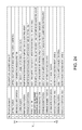
- FIG. 24 is a table showing cap positions in the cap movement direction.
- FIG. 25A describes wiper positions in the wiper movement direction.
- FIG. 25B describes wiper positions in the wiper movement direction.
- FIG. 25C describes wiper positions in the wiper movement direction.
- FIG. 26A describes the upright positions of the wiper.
- FIG. 26B is a table of the upright positions of the wiper.
- FIG. 27A describes the wiping start positions.
- FIG. 27B describes the wiping start positions.
- FIG. 27C is a table of the describes the wiping start positions.
- FIG. 1 is a vertical section view showing the general configuration of an inkjet printer according to an embodiment of the disclosure.
- the inkjet printer 1 (also referred to below as simply printer 1 ) has a roll paper compartment 2 , and a paper roll 3 made by winding continuous recording paper P into a roll is loaded in the roll paper compartment 2 .
- a recording paper conveyance path 5 is formed inside the printer 1 from the roll paper compartment 2 to the paper exit 4 formed in the front of the printer.
- a feed roller 6 , paper guide 7 , conveyance roller pair 8 , and platen 9 are disposed to the recording paper conveyance path 5 from the upstream side to the downstream side in the recording paper conveyance direction.
- An inkjet head 11 mounted on a head carriage 10 is also disposed. The head carriage 10 moves the nozzle face 11 a of the inkjet head 11 to a printing position on the recording paper conveyance path 5 opposite the platen 9 , and to a home position removed from the recording paper conveyance path 5 .
- the maintenance device 40 described below is disposed to the home position.
- the conveyance roller pair 8 includes a drive roller 8 a and a driven roller 8 b .
- the drive roller 8 a is driven forward and reverse by a paper feed motor 12 .
- Ink is supplied to the inkjet head 11 from an ink cartridge 14 installed to an ink cartridge holder 13 .
- ink cartridge 14 installed to an ink cartridge holder 13 .
- four colors of ink, black, cyan, magenta, and yellow, are supplied to the inkjet head 11 .
- the inkjet head 11 is a line inkjet head.
- the recording paper P delivered from the paper roll 3 in the roll paper compartment 2 is conveyed through the recording paper conveyance path 5 .
- the inkjet head 11 prints on the recording paper P conveyed over the platen 9 . After printing, the recording paper P is discharged to the front from the paper exit 4 at the front of the printer.
- FIG. 2A describes the relationship between the printing position and the home position of the inkjet head 11 when the printer 1 is seen from above
- FIG. 2B describes the relationship between the printing position and home position when seen from the front of the printer
- the inkjet head 11 is a line inkjet head comprising plural inkjet heads.
- the inkjet head 11 has a first head 11 A and a second head 11 B.
- the nozzle rows of the first and second heads 11 A, 11 B are long enough to cover the widthwise direction of the print area of the recording paper P (the width in the direction perpendicular to the recording paper P conveyance direction).
- the first and second heads 11 A, 11 B of the line inkjet head are installed on the head carriage 10 with the nozzle faces 11 a facing down.
- the nozzle faces 11 a are level and facing down.
- a platen gap G of a preset dimension is formed between the surface of the platen 9 and the nozzle face 11 a of each head 11 A, 11 B.
- the maintenance device 40 is disposed beside the platen 9 .
- the head carriage 10 moves the inkjet head 11 to the printing position A opposite the platen 9 , and the home position B completely removed from the recording paper conveyance path 5 (the position indicated by a dot-dash line in FIG. 2A and FIG. 2B ).
- the nozzle face 11 a of the inkjet head 11 is opposite the maintenance device 40 .
- the inkjet head 11 is disposed with its long side in the transverse position in the direction perpendicular to the conveyance direction of the recording paper P. In this position, the ink nozzle row for each color disposed to the first and second heads 11 A, 11 B covers the widthwise direction of the print area of the recording paper P.
- the inkjet head 11 In the home position B, the inkjet head 11 is in a position rotated 90 degrees to its position at the printing position A. More specifically, the inkjet head 11 is positioned with its long side in the longitudinal position aligned with the conveyance direction.
- FIG. 3 describes the path of movement of the head carriage 10 on which the inkjet head 11 is mounted.
- the printer 1 prints on the recording paper P by positioning and stopping the inkjet head 11 at the printing position A, and executing the ink ejection operation each time the recording paper P advances a specific pitch.
- the printer 1 retracts the inkjet head 11 to the home position B removed from above the platen 9 , and waits with the inkjet head 11 at the home position B.
- the maintenance device 40 performs a maintenance operation that prevents or eliminates clogging of the ink nozzles of the inkjet head 11 while the inkjet head 11 is in the standby position.
- the maintenance device 40 raises a cap disposed at the top end to cap the nozzle face 11 a . Ink is then discharged (flushed) from the ink nozzles of the inkjet head 11 into the cap of the maintenance device 40 as necessary.
- the maintenance device 40 also performs an operation that suctions ink from the cap.
- a wiper for wiping the nozzle face 11 a is also disposed to the maintenance device 40 . To resume printing, the cap and wiper are retracted to the down side, and the inkjet head 11 moves to the printing position A.
- FIG. 4 shows the nozzle face 11 a of the inkjet head 11 .
- This figure shows the nozzle configuration as seen from above the printer 1 looking through the nozzle face 11 a .
- Four head units 1 - 1 to 1 - 4 with black and cyan ink nozzle rows are contained in the first head 11 A.
- the four head units 1 - 1 to 1 - 4 are disposed in two rows with two head units each in the ink nozzle row direction.
- the head units 1 - 1 to 1 - 4 are staggered between the rows.
- head units 2 - 1 to 2 - 4 with yellow and magenta ink nozzle rows are similarly contained in the second head 11 B.
- the four head units 2 - 1 to 2 - 4 are disposed in two rows with two head units each in the ink nozzle row direction.
- the head units 2 - 1 to 2 - 4 are staggered between the rows.
- the configuration of caps in the maintenance device 40 described below is set to match the configuration of these eight head units 1 - 1 to 1 - 4 , and 2 - 1 to 2 - 4 .
- the head cover surface 10 b is surrounded by the bottom part 10 a of the head carriage 10 .
- the nozzle face 11 a of the inkjet head 11 refers to these nozzle faces 1 - 1 a to 1 - 4 a , 2 - 1 a to 2 - 4 a.
- FIG. 5A is an oblique view and FIG. 5B is a side view of the maintenance device 40 .
- FIG. 6 is an exploded oblique view showing main parts of the maintenance device 40 .
- the general configuration of the maintenance device 40 is described with reference to these figures.
- the direction the cap that caps the nozzle faces 1 - 1 a to 1 - 4 a moves is referred to below as the cap movement direction V
- the direction in which the cap approaches the nozzle face in this cap movement direction V is called the capping direction V 1
- the direction the cap moves away from the nozzle face is called the uncapping direction V 2 .
- the direction the wiper that wipes the nozzle faces 1 - 1 a to 1 - 4 a moves is called the wiper movement direction H
- the direction the wiper moves when wiping the nozzle face is called the wiping direction H 2 (wiper retraction direction H 2 )
- the direction opposite the wiping direction is H 1 (wiper advancing direction H 1 ).
- the maintenance device 40 is basically rectangular overall, and has a device frame 50 , a cap unit 60 , a wiper unit 70 , an ink suction pump 94 , a cap drive transfer mechanism 80 , and a wiper-pump drive transfer mechanism 90 .
- the cap unit 60 , ink suction pump 94 , cap drive transfer mechanism 80 , and wiper-pump drive transfer mechanism 90 are disposed to the device frame 50 .
- the device frame 50 has a rectangular bottom panel 51 , and side walls 52 , 53 and end walls 54 , 55 that respectively rise from the opposite long sides and opposite short sides of the bottom panel 51 .
- Two guide posts 56 a , 56 b are attached perpendicularly to the bottom panel 51 of the device frame 50 .
- the cap unit 60 can move along the guide posts 56 a , 56 b .
- the cap drive transfer mechanism 80 moves the cap unit 60 in the direction along the guide posts 56 a , 56 b , that is, in the cap movement direction V (capping direction V 1 and uncapping direction V 2 ).
- the cap unit 60 has the same number ( 8 ) of caps 64 ( 1 ) to 64 ( 4 ), 65 ( 1 ) to 65 ( 4 ) as head units 1 - 1 to 1 - 4 , 2 - 1 to 2 - 4 .
- Caps 64 ( 1 ) to 64 ( 4 ), 65 ( 1 ) to 65 ( 4 ) cap the nozzle faces 1 - 1 a to 1 - 4 a , 2 - 1 a to 2 - 4 a of the head units 1 - 1 to 1 - 4 , 2 - 1 to 2 - 4 .
- the ink suction pump 94 suctions ink from the caps 64 ( 1 ) to 64 ( 4 ), 65 ( 1 ) to 65 ( 4 ). Ink is thus suctioned from the ink nozzles of the capped head units 1 - 1 to 1 - 4 , 2 - 1 to 2 - 4 .
- the suctioned ink is recovered in a waste ink tank (not shown in the figure) disposed to the ink cartridge 14 , for example.
- the wiper unit 70 has four wipers 75 ( 1 ) to 75 ( 4 ) that wipe the nozzle faces 1 - 1 a to 1 - 4 a , 2 - 1 a to 2 - 4 a of the head units 1 - 1 to 1 - 4 , 2 - 1 to 2 - 4 .
- Wiper 75 ( 1 ) wipes the nozzle faces 1 - 1 a , 1 - 3 a of the head units 1 - 1 , 1 - 3 ; wiper 75 ( 2 ) wipes the nozzle faces 1 - 2 a , 1 - 4 a of head units 1 - 2 , 1 - 4 ; wiper 75 ( 3 ) wipes the nozzle faces 2 - 1 a , 2 - 3 a of head units 2 - 1 , 2 - 3 ; and wiper 75 ( 4 ) wipes the nozzle faces 2 - 2 a , 2 - 4 a of head units 2 - 2 , 2 - 4 .
- the wipers 75 ( 1 ) to 75 ( 4 ) move bidirectionally in the wiper movement direction H along the long side of the maintenance device 40 .
- the wiper movement direction H is parallel to the ink nozzle line of the inkjet head 11 at the home position B.
- the wiper-pump drive transfer mechanism 90 has a drive motor 91 that drives the wiper unit 70 and ink suction pump 94 .
- the wiper-pump drive transfer mechanism 90 also has a drive switching mechanism 100 (see FIG. 8A ).
- the drive switching mechanism 100 switches to a state enabling moving the wiper or a state enabling driving the suction pump according to the position of the cap unit 60 , that is, the position to which the caps 64 ( 1 ) to 64 ( 4 ), 65 ( 1 ) to 65 ( 4 ) move.
- the cap unit 60 has a cap frame 61 , and first and second cap bases 62 , 63 (cap support members) affixed to the cap frame 61 .
- caps 64 ( 1 ) to 64 ( 4 ) are disposed to the first cap base 62
- caps 65 ( 1 ) to 65 ( 4 ) are disposed to the second cap base 63 .
- caps 64 ( 1 ) to 64 ( 4 ) are also referred to as caps 64
- caps 65 ( 1 ) to 65 ( 4 ) are referred to as caps 65 .
- Caps 64 ( 1 ) to 64 ( 4 ) have the same shape, and have a lip (cap opening edge) with a long, narrow rectangular profile that can cover and enclose the nozzle faces 1 - 1 a to 1 - 4 a , 2 - 1 a to 2 - 4 a of the head units 1 - 1 to 1 - 4 , 2 - 1 to 2 - 4 .
- Caps 64 ( 1 ), 64 ( 3 ) are disposed in line in the lengthwise direction thereof with a specific gap therebetween.
- Caps 64 ( 2 ), 64 ( 4 ) are also disposed in line in the lengthwise direction thereof with a specific gap therebetween.
- the caps 64 ( 1 ), 64 ( 3 ) in one cap row are staggered relative to the caps 64 ( 2 ), 64 ( 4 ) in the other cap row.
- the caps 64 ( 1 ) to 64 ( 4 ) are each supported on the first cap base 62 by a pair of spring members 62 a (cap pressure members) such as a pair of compression springs (see FIG. 18A and FIG. 22A ).
- the pair of spring members 62 a are disposed between the lengthwise ends of each cap 64 ( 1 ) to 64 ( 4 ) and the bottom part of the first cap base 62 .
- the caps 65 ( 1 ) to 65 ( 4 ) on the second cap base 63 have the same shape as the caps 64 ( 1 ) to 64 ( 4 ), and are arranged in the same configuration.
- the caps 65 ( 1 ) to 65 ( 4 ) are each supported on the second cap base 63 by a pair of spring members 63 a (cap pressure members) such as a pair of compression springs.
- the pair of spring members 63 a are disposed at the lengthwise ends of the caps ( 1 ) to 65 ( 4 ).
- Caps 64 ( 1 ) to 64 ( 4 ) respectively cap the head units 1 - 1 to 1 - 4 of the first head 11 A of the inkjet head 11 shown in FIG. 4 .
- Caps 65 ( 1 ) to 65 ( 4 ) respectively cap the head units 2 - 1 to 2 - 4 of the second head 11 B shown in FIG. 4 .
- the cap unit 60 has a diagonal cap removal mechanism 160 as further described below (see FIG. 18A to FIG. 18C ).
- the diagonal cap removal mechanism 160 holds the lip face (the end surface of the cap opening edge) parallel to the nozzle face. In the uncapping operation, the diagonal cap removal mechanism 160 tilts the lip face to the nozzle face.
- the wiper unit 70 has a rectangular wiper frame 71 .
- a pair of guide shafts 72 extend parallel to the long side of the wiper frame 71 between the short side ends of the wiper frame 71 .
- a wiper holder unit 73 is disposed slidably along the pair of guide shafts 72 .
- the wiper unit 70 One lengthwise end of the wiper unit 70 is the home position 73 A of the wiper holder unit 73 .
- the wiper holder unit 73 can slide along the guide shafts 72 between the home position 73 A and the opposite end of the wiper unit 70 .
- the wiper movement direction H is the direction of wiper holder unit 73 movement determined by the guide shafts 72 .
- wiper holders 74 ( 1 ) to 74 ( 4 ) are disposed to the wiper holder unit 73 .
- One wiper 75 ( 1 ) to 75 ( 4 ) is disposed to each of the wiper holders 74 ( 1 ) to 74 ( 4 ).
- wiper holders 74 ( 1 ) to 74 ( 4 ) are also referred to as wiper holders 74
- wipers 75 ( 1 ) to 75 ( 4 ) as wipers 75 .
- Wiper 75 ( 1 ) wipes the nozzle faces of the two head units 1 - 1 , 1 - 3 in the outside row of the first head 11 A shown in FIG. 4 .
- Wiper 75 ( 2 ) wipes the nozzle faces of the other two head units 1 - 2 , 1 - 4 .
- wiper 75 ( 3 ) wipes the two head units 2 - 1 , 2 - 3 on the inside row of second head 11 B shown in FIG. 4 .
- Wiper 75 ( 4 ) wipes the two remaining head units 2 - 2 , 2 - 4 .
- FIG. 7A and FIG. 7B show the cap drive transfer mechanism 80 that moves the cap unit 60 .
- FIG. 7A is an exploded view without the side walls 52 , 53 of the device frame 50
- FIG. 7B is an oblique view with the cap unit 60 assembled to the device frame 50 .
- the cap drive transfer mechanism 80 has a pair of spiral cams 81 a , 81 b disposed to the device frame 50 .
- the spiral cams 81 a , 81 b are disposed adjacent to the guide posts 56 a , 56 b .
- the spiral cams 81 a , 81 b are supported on the bottom panel 51 freely rotatably around a center axis perpendicular to the bottom panel 51 .
- a spiral channel is formed in the direction of the center axis in the outside surface of the spiral cams 81 a , 81 b .
- the top side of each spiral channel is a cam surface 82 a , 82 b that extends at a specific pitch in a vertical spiral.
- a pair of cam follower rollers 66 (only one roller 66 is shown in the figure) is disposed freely rotatably to the cap frame 61 of the cap unit 60 .
- the rollers 66 can travel freely along the cam surface 82 a , 82 b .
- a guide hole 85 (only one guide hole 85 is shown in the figure) is formed at a position adjacent to each roller 66 in the cap frame 61 .
- the guide posts 56 a , 56 b pass freely slidably through the guide holes 85 .
- a motor 83 is located at one lengthwise end of the bottom panel 51 .
- a motor disposed to the main part of the inkjet printer 1 can be used as the drive source instead of the motor 83 .
- Torque from the motor 83 is transferred through a belt and pulley power transfer mechanism 84 to the spiral cams 81 a , 81 b .
- the spiral cams 81 a , 81 b rotate synchronously on their axes of rotation.
- the pair of spiral cams 81 a , 81 b turn.
- the rollers 66 of the cap unit 60 riding on the spiral cam surfaces 82 a , 82 b roll along the cam surfaces 82 a , 82 b .
- the cap unit 60 moves in the cap movement direction V, in the top-bottom direction of the printer in this embodiment, guided by the pair of guide posts 56 a , 56 b .
- the caps 64 ( 1 ) to 64 ( 4 ), 65 ( 1 ) to 65 ( 4 ) cap the nozzle faces of the head units 1 - 1 to 1 - 4 , 2 - 1 to 2 - 4 of the inkjet head 11 from below.
- the position of the cap unit 60 in the cap movement direction V is controlled based on the output of a position detector 86 .
- the position detector 86 is a photo interrupter, for example, and is disposed adjacent to the motor 83 .
- An interrupter 86 a is disposed to the cap frame 61 of the cap unit 60 .
- the position of the cap unit 60 can be controlled based on the output of the position detector 86 and the encoder pulse count of a rotary encoder (not shown in the figure) built in to the motor 83 . More specifically, the position of the caps 64 ( 1 ) to 64 ( 4 ) and 65 ( 1 ) to 65 ( 4 ) in the cap movement direction V can be known.
- FIG. 8A is an oblique view showing the wiper-pump drive transfer mechanism 90 and cap unit 60 installed to the device frame 50 , omitting part of the wiper-pump drive transfer mechanism 90 and the side walls 52 , 53 of the device frame 50 .
- FIG. 8B and FIG. 8C are oblique views of the wiper-pump drive transfer mechanism 90 .
- FIG. 8D is a schematic skeleton diagram of main parts of the wiper-pump drive transfer mechanism 90
- FIG. 8E and FIG. 8F describe the operation of the drive switching mechanism 100 .
- FIG. 9A is an oblique view showing the wiper-pump drive transfer mechanism 90 and cap unit 60 installed to the device frame 50 , omitting the side walls 52 , 53 of the device frame 50 .
- FIG. 9B and FIG. 9C describe the power transmission path to the wiper side.
- FIG. 10 is an oblique view showing the wiper-pump drive transfer mechanism 90 and cap unit 60 installed to the device frame 50 .
- the side walls 52 , 53 of the device frame 50 are omitted, and the wiper holder unit 73 of the wiper unit 70 is assembled to the wiper-pump drive transfer mechanism 90 .
- the wiper-pump drive transfer mechanism 90 has a drive motor 91 attached to the bottom panel 51 .
- a motor mounted on the main part of the inkjet printer 1 could be used as the drive source.
- Rotation of the drive motor 91 is transferred through a transmission gear train 92 to the input shaft 93 a of a planetary gear speed reducer 93 .
- the planetary gear speed reducer 93 includes a sun gear 93 d (see FIG. 8D ) connected coaxially or formed in unison with the input shaft 93 a , a planetary gear 93 e (see FIG. 8D ) meshed with the sun gear 93 d , an internal gear 93 b meshed with the planetary gear 93 e , and a planetary carrier 93 c that supports the planetary gear 93 e freely rotatably.
- the ink suction pump 94 is coaxially disposed behind the planetary gear speed reducer 93 .
- the operating shaft (not shown in the figure) of the ink suction pump 94 is connected coaxially to the internal gear 93 b of the planetary gear speed reducer 93 .
- the speed reduced rotation extracted from the planetary gear speed reducer 93 rotationally drives the ink suction pump 94 to suction ink.
- a drive-side external gear 93 f is formed in unison with the planetary carrier 93 c .
- the drive-side external gear 93 f is connected to a drive sprocket 96 for driving a belt through an external transfer gear 95 a and a follower-side external gear 95 b .
- the drive sprocket 96 is rotationally driven by the speed-reduced rotation extracted from the planetary carrier 93 c.
- One lengthwise end of the wiper frame 71 of the wiper unit 70 is the home position 73 A of the wiper holder unit 73 .
- a driven sprocket 97 is attached freely rotatably to the end of the wiper frame 71 on the home position 73 A side.
- a drive belt 98 is mounted on the drive sprocket 96 and the driven sprocket 97 .
- a slider 99 is affixed to the drive belt 98 .
- a hole 73 a that engages a protrusion 99 a formed on the slider 99 is formed in the wiper holder unit 73 .
- the four wipers 75 ( 1 ) to 75 ( 4 ) mounted on the wiper holder unit 73 respectively wipe the nozzle faces of head units 1 - 1 , 1 - 3 , head units 1 - 2 , 1 - 4 , head units 2 - 1 , 2 - 3 , and head units 2 - 2 , 2 - 4 .
- the wiper drive transfer mechanism unit of the wiper-pump drive transfer mechanism 90 is described in further detail below with reference to FIG. 9A , FIG. 9B , and FIG. 9C .
- the wiper drive transfer mechanism unit includes the drive-side external gear 93 f and external transfer gear 95 a disposed to the device frame 50 , and the follower-side external gear 95 b disposed to the wiper frame 71 .
- the external transfer gear 95 a meshes with both the drive-side external gear 93 f and follower-side external gear 95 b.
- the external transfer gear 95 a is supported freely rotatably on the distal end part of a pivot frame 201 .
- the base end of the pivot frame 201 is supported by the cover 90 A of the wiper-pump drive transfer mechanism 90 freely pivotably around the center axis of the drive-side external gear 93 f . Therefore, the external transfer gear 95 a can revolve around the center axis of the drive-side external gear 93 f while remaining meshed with the drive-side external gear 93 f.
- a connector plate 202 connects the shaft part of the external transfer gear 95 a with the shaft part of the follower-side external gear 95 b .
- the external transfer gear 95 a and follower-side external gear 95 b are therefore kept always engaged.
- the wiper unit 70 is supported movably in the cap movement direction V by the device frame 50 .
- the wiper unit 70 is also pushed in the capping direction V 1 by a tension spring 108 b , and raised (floats) above the device frame 50 .
- the follower-side external gear 95 b on the wiper frame 71 side moves in the same direction therewith.
- the external transfer gear 95 a meshed with the follower-side external gear 95 b revolves around the center axis of the drive-side external gear 93 f in conjunction with movement of the follower-side external gear 95 b while remaining meshed with the follower-side external gear 95 b .
- Power for moving the wiper can be transferred from the device frame 50 side to the wiper frame 71 side irrespective of movement of the wiper frame 71 .
- This configuration does not require disposing all parts of the wiper drive transfer mechanism unit on the moving wiper frame 71 , and is advantageous for reducing the weight of the wiper unit 70 .
- the wiper holder unit 73 moves slightly in the opposite direction as the wiping direction H 2 . More specifically, the wipers 75 ( 1 ) to 75 ( 4 ) moves slightly in the opposite direction H 1 as the wiping direction H 2 .
- each of the wipers 75 ( 1 ) to 75 ( 4 ) move in the direction H 1 opposite the wiping direction H 2 in a direction slightly inclined to the direction perpendicular to the nozzle faces.
- This wiper action can prevent foreign matter such as ink on the wiper from spreading as described below.
- the drive switching mechanism 100 is disposed to the wiper-pump drive transfer mechanism 90 , and can switch between a wiper driving position and a pump driving position.
- the drive switching mechanism 100 switches according to the position of the cap unit 60 . The switching operation therefore depends upon the position of the caps 64 ( 1 ) to 64 ( 4 ), 65 ( 1 ) to 65 ( 4 ).
- the drive switching mechanism 100 has a first latch mechanism 102 that latches the internal gear 93 b so that it cannot turn by means of the spring force of a first tension spring 101 , and a second latch mechanism 104 that latches the planetary carrier 93 c so that it cannot turn by means of the spring force of a second tension spring 103 .
- the first latch mechanism 102 has a first latch lever 102 a
- the second latch mechanism 104 has a second latch lever 104 a disposed to a position above the first latch lever 102 a in the figure (a position on the side in the capping direction V 1 ).
- a first cam surface 105 that can push the first latch lever 102 a in resistance to the spring force due to the movement of the cap unit 60 is formed on the cap frame 61 of the cap unit 60 at a position opposite the first latch lever 102 a .
- a second cam surface 106 that can push the second latch lever 104 a in resistance to the spring force due to the movement of the cap unit 60 is also formed on the cap frame 61 at a position opposite the second latch lever 104 a.
- the first and second cam surfaces 105 , 106 are formed at different positions in the cap movement direction V.
- the first latch lever 102 a is pushed against the spring force, the first latch mechanism 102 is disengaged, and the internal gear 93 b changes to the free rotation state.
- the second latch lever 104 a is pushed against the spring force, the second latch mechanism 104 is disengaged, and the planetary carrier 93 c changes to the free rotation state.
- the wiper-pump drive transfer mechanism 90 changes to the pump driving state or the wiper driving state according to the position the cap unit 60 is moved in the cap movement direction V by the drive switching mechanism 100 .
- the timing that the drive switching mechanism 100 changes can be easily adjusted or changed.
- a switching mechanism that is small and compact compared with a mechanism that changes the drive transfer direction using members such as a cylindrical cam or intermittent gear can therefore be achieved.
- wiping the nozzle face with a constant wiping pressure may not be possible when the nozzle face is long in the nozzle row direction, such as with a line inkjet head.
- the maintenance device may be tilted in the nozzle row direction (wiper movement direction) relative to the nozzle face of the inkjet head. In this configuration, the wiper pressure on the nozzle face varies while wiping, and the nozzle face of each head unit cannot be wiped with a constant wiping pressure.
- the wiper unit 70 in this example is supported by the device frame 50 as follows.
- FIG. 11A is an oblique view showing the wiper unit 70 assembled with the cap unit 60 .
- FIG. 11B is an enlarged oblique view showing part of the side.
- FIG. 11C describes the relationship between the device frame 50 , cap unit 60 , and wiper frame 71 .
- the wiper unit 70 is supported by the device frame 50 in a position pulled up (pushed) by spring force in the capping direction.
- a guide 107 a is formed projecting in the capping direction V 1 at each of the four corners of the device frame 50 .
- Each of the four corners of the wiper frame 71 of the wiper unit 70 is a guided part 107 b that is guided in the cap movement direction V along the inside surface of the corresponding guide 107 a .
- a spring catch 108 a is formed at the top edge of each guide 107 a of the device frame 50 .
- One end of a tension spring 108 b is mounted on each spring catch 108 a .
- a spring catch 108 c is also formed at a position on the inside of each of the four corners of the wiper frame 71 .
- the bottom end of the tension spring 108 b is mounted on this spring catch 108 c.
- the wiper unit 70 is thus held movably in the cap movement direction V relative to the device frame 50 , and is attached to the device frame 50 by the four tension springs 108 b so that the wiper unit 70 floats. More specifically, the wiper unit 70 is constantly pushed up (in the capping direction) by the tension springs 108 b , and the wiper unit 70 can be pushed down (in the uncapping direction) against the spring force of the tension springs 108 b.
- a stop that regulates the up position (the position in the capping direction V 1 ) of the wiper unit 70 is disposed between the device frame 50 and the wiper frame 71 of the wiper unit 70 .
- a pair of engaging tabs 109 a are formed on the end panel 54 of the device frame 50 .
- a pair of engaging frames 109 b through which the engaging tabs 109 a pass are formed in the wiper frame 71 .
- an engaging tab 109 c is also formed on the other end panel 55 of the device frame 50 .
- An engaging frame 109 d through which the engaging tab 109 c passes is formed in the wiper frame 71 .
- the wiper unit 70 that thus floats on the device frame 50 moves together with the cap unit 60 in a specific range in the cap movement direction V. Described with reference to FIG. 11A to FIG. 11C , rectangular frames 71 c are formed set back to the inside in both side panels 71 b of the wiper frame 71 of the wiper unit 70 . A pair of engaging tabs 61 a that project to the side are formed on both sides of the cap frame 61 of the cap unit 60 .
- the wiper unit 70 When the cap unit 60 moves from the capping position in the uncapping direction V 2 , the wiper unit 70 , which is pulled up by the tension spring 108 b , does not move. When the cap unit 60 moves a specific distance from the capping position in the uncapping direction V 2 , the engaging tabs 61 a engage the rectangular frames 71 c . Thereafter, the wiper unit 70 is moved forcibly in the uncapping direction V 2 together with the cap unit 60 .
- the wiper unit 70 moves in the capping direction with the cap unit 60 due to the spring force of the tension springs 108 b.
- the engaging tabs 61 a of the cap unit 60 are separated in the capping direction V 1 from the rectangular frames 71 c of the wiper frame 71 as shown in FIG. 11B .
- the wiper unit 70 is therefore held by the spring force of the tension springs 108 b at a specific position by the engagement of the engaging tabs 109 a , 109 c and engaging frames 109 b , 109 d.
- a contact surface 71 a is formed at an elevated position along both lengthwise edges at the top of the wiper frame 71 of the wiper unit 70 .
- these contact surfaces 71 a contact a part on the inkjet head 11 side, specifically the bottom of the head carriage 10 carrying the inkjet head 11 (the rectangular bottom 10 a surrounding the first and second heads 11 A, 11 B in FIG. 4 ) in this example, before the lips (the end surface of the cap opening edge) of the caps 64 ( 1 ) to 64 ( 4 ) and 65 ( 1 ) to 65 ( 4 ).
- the wiper unit 70 carrying the wipers 75 ( 1 ) to 75 ( 4 ) is supported in a floating state on the device frame 50 .
- the wiper unit 70 is released from the cap unit 60 and pushed in the capping direction V 1 by the spring force of the tension springs 108 b .
- the contact surface 71 a of the wiper frame 71 of the wiper unit 70 contacts the bottom of the head carriage 10 on the inkjet head 11 side.
- the wiper unit 70 is positioned to the nozzle face 11 a of the inkjet head 11 . Even if the inkjet head 11 is tilted relative to the maintenance device 40 , the wiper unit 70 is positioned to follow the slope of the inkjet head 11 .
- Each of the plural wipers 75 ( 1 ) to 75 ( 4 ) included in the wiper unit 70 is positioned with a specific gap to the corresponding nozzle faces of the head units 1 - 1 to 1 - 4 , 2 - 1 to 2 - 4 of the inkjet head 11 .
- Each of the wipers 75 ( 1 ) to 75 ( 4 ) can therefore be pressed with a constant wiping force against the corresponding nozzle faces, and the nozzle faces can be reliably wiped with appropriate pressure. More specifically, when the contact surface 71 a of the wiper frame 71 is in contact with the bottom of the carriage 10 , the wipers 75 ( 1 ) to 75 ( 4 ) are raised to the upright position as described below.
- each wiper 75 ( 1 ) to 75 ( 4 ) thus positioned are moved in the wiping direction H 2 , the distal end of each wiper can be pressed with specific pressure against the nozzle faces 1 - 1 a to 1 - 4 a , 2 - 1 a to 2 - 4 a of the head units 1 - 1 to 1 - 4 , 2 - 1 to 2 - 4 in the inkjet head 11 .
- the inkjet head is composed of plural head units, suctioning ink only from the head units that require maintenance is desirable. Being able to perform selective suctioning with a small, compact mechanism is advantageous for reducing the size and cost of the maintenance device.
- the maintenance device 40 in this example has a selective suction mechanism for individually selectively suctioning each of the plural caps 64 ( 1 ) to 64 ( 4 ) and 65 ( 1 ) to 65 ( 4 ) using the suction pump 94 .
- the maintenance device 40 has a selective suction mechanism that selectively suctions ink from the head units 1 - 1 to 1 - 4 , 2 - 1 to 2 - 4 capped by the plural caps 64 ( 1 ) to 64 ( 4 ) and 65 ( 1 ) to 65 ( 4 ).
- FIG. 12A to FIG. 12D describe the selective suction mechanism.
- a selective suction mechanism that selects caps 65 ( 1 ) to 65 ( 4 ) is disposed on the one side wall 52 side of the device frame 50 .
- a selective suction mechanism that selects caps 64 ( 1 ) to 64 ( 4 ) is disposed on the other side wall 53 side. Because both selective suction mechanisms are basically identical, the selective suction mechanism that selects caps 64 ( 1 ) to 64 ( 4 ) is described below.
- the caps 64 ( 1 ) to 64 ( 4 ) and the suction port of the suction pump 94 are connected through a suction tube 110 that branches into four parts from the suction port ( FIG. 11A ), and four valves 112 A to 115 A disposed on the side wall 53 side of the device frame 50 .
- the valves 112 A to 115 A are normally-closed valves that are held in a normally closed state by an internal diaphragm (not shown in the figure).
- valve 112 A to 115 A When the operating lever 112 a to 115 a of a valve 112 A to 115 A is pressed, the diaphragm displaces and the valve opens. When pressure on the operating lever 112 a to 115 a is released, the valve closes again due to the elastic resilience of the diaphragm. These valves 112 A to 115 A are arrayed in the wiper movement direction H. When the valves 112 A to 115 A open, the ink suction path that suctions ink from the caps 64 ( 1 ) to 64 ( 4 ) opens, and ink can be suctioned by the ink suction pump 94 .
- a rectangular window that is long in the wiper movement direction H is formed in the side wall 53 opposite the operating levers 112 a to 115 a of the valves 112 A to 115 A.
- a guide shaft 116 a extending in the wiper movement direction H is disposed along the top edge of the window.
- a valve selector 117 A is disposed slidably along this guide shaft 116 a and a guide rail 116 b formed by the bottom edge of the window.
- the valve selector 117 A can move along the guide shaft 116 a to a position opposite the operating levers 112 a to 115 a of the valves 112 A to 115 A.
- the valve selector 117 A has an engaging tab 117 a protruding in the capping direction along the outside surface of the side wall 53 , and a lever operator 117 b that protrudes to the inside of the side wall 53 .
- the valve selector 117 A moves to the position opposite an operating lever 112 a to 115 a of a valve 112 A to 115 A, the operating lever 112 a to 115 a is pushed by the lever operator 117 b and the valve 112 A to 115 A opens.
- a selector hook 118 A protruding in the uncapping direction V 2 is disposed to the side of the wiper holder unit 73 , which moves in the wiper movement direction H.
- a recess 118 a with a shape that complements the engaging tab 117 a is formed in the selector hook 118 A.
- the engaging tab 117 a of the valve selector 117 A can be inserted in the capping direction to this recess 118 a .
- the valve selector 117 A can be moved along the guide shaft 116 a in the wiper movement direction H by the wiper holder unit 73 .
- the selector hook 118 A is therefore positioned to the valve selector 117 A when the wiper holder unit 73 moves in the wiper movement direction H.
- the cap unit 60 is then moved a specific distance in the uncapping direction V 2 .
- the wiper unit 70 moves in the same direction, and the selector hook 118 A of the wiper unit 70 engages the valve selector 117 A.
- the valve selector 117 A is positioned in the wiper movement direction H to one of the valves 112 A to 115 A.
- the operating lever 112 a to 115 a of the valve 112 A to 115 A to which the valve selector 117 A is positioned is held in the open position by the lever operator 117 b of the valve selector 117 A. Ink can therefore be suctioned by the suction pump 94 from the corresponding cap 65 ( 1 ) to 65 ( 4 ) through the valve 112 A to 115 A that is held open.
- the valve 112 A to 115 A that performs the selective suction operation can be selected by moving the cap unit 60 ( cap ) in the cap movement direction V, and moving the wiper holder unit 73 (wiper) in the wiper movement direction H.
- a selective suction operation can therefore be achieved with a small, compact configuration without using a cylindrical cam, intermittent gear, rocker, or other part for changing the selection.
- An all-valve operating lever 119 A is disposed to the device frame 50 .
- the all-valve operating lever 119 A can simultaneously operate the operating lever 112 a to 115 a of each valve 112 A to 115 A.
- the valve selector 117 A is positioned adjacent to operating lever 112 a in the wiper movement direction H, the all-valve operating lever 119 A is depressed by the lever operator 117 b of the valve selector 117 A.
- valve selector 117 A When the valve selector 117 A is positioned away from the valves 112 A to 115 A and all-valve operating lever 119 A, all of the valves 112 A to 115 A are kept closed.
- a lever depressing operator 61 c that protrudes to the inside is formed on the side wall 61 b of the cap frame 61 of the cap unit 60 .
- the position of this lever depressing operator 61 c is set as described below in the cap movement direction V.
- the lever depressing operator 61 c is positioned where it can depress the all-valve operating lever 119 A.
- valve selector 117 A slides along the guide rail 116 b , the operating levers 112 a to 115 a of the valves 112 A to 115 A are depressed by the all-valve operating lever 119 A, and the valve selector 117 A can be slid without interfering with the operating levers 112 a to 115 a.
- the mechanism for selectively suctioning the other caps 65 ( 1 ) to 65 ( 4 ) is identically configured. However, the shape of the valve selectors on each side differ slightly so that each of the caps 64 ( 1 ) to 64 ( 4 ) and 65 ( 1 ) to 65 ( 4 ) can be selectively suctioned individually.
- valves, valve selector, selector hook, and all-valve operating lever disposed on the side wall 52 side for selecting caps 65 ( 1 ) to 65 ( 4 ) are identified as valves 112 B to 115 B, valve selector 117 B, selector hook 118 B, and all-valve operating lever 119 B.
- the selector hook and valve selector on one side are first engaged, and the selector hook and valve selector on the other side are then engaged.
- the engaging tab 117 a of the other valve selector 117 B is shorter than the engaging tab 117 a of the one valve selector 117 A.
- the valve selectors 117 A, 117 B move in the uncapping direction V 2 , they respectively engage the selector hooks 118 A, 118 B (ST 1 in FIG. 12D ).
- the wiper holder unit 73 then moves in the wiper movement direction H to move the valve selector 117 B with the shorter engaging tab 117 a to the targeted valve position in the wiper movement direction H.
- the other valve selector 117 A also moves to the same position at the same time.
- valve selector 117 A When both valve selectors 117 A, 117 B then move in the capping direction V 1 , the valve selector 117 B with the shorter engaging tab 117 a separates from the selector hook 118 B first. At this time, the other valve selector 117 A with the longer engaging tab 117 a is engaged with the selector hook 118 A (ST 2 in FIG. 12D ). If the wiper holder unit 73 is then moved in the wiper movement direction H, only the valve selector 117 A that is engaged moves. As a result, the valve selector 117 A can be moved to the targeted valve position.
- both valve selectors 117 A, 117 B After the targeted valve positions are selected by both valve selectors 117 A, 117 B, the cap unit 60 is moved in the capping direction. As a result, both valve selectors 117 A, 117 B separate from the selector hooks 118 A, 118 B (ST 3 in FIG. 12D ).
- the cap from which ink is to be suctioned can thus be freely selected from the caps 64 ( 1 ) to 64 ( 4 ) on one side. Without being affected by the selection of caps 64 ( 1 ) to 64 ( 4 ), the cap from which is to be suctioned can also be freely selected from the caps 65 ( 1 ) to 65 ( 4 ) on the other side.
- the inkjet head is composed of plural head units, wiping the head units that require maintenance is desirable. Being able to perform selective wiping with a small, compact mechanism is advantageous for reducing the size and cost of the maintenance device.
- the maintenance device 40 in this example has four wipers 75 ( 1 ) to 75 ( 4 ) for wiping the nozzle faces 1 - 1 a to 1 - 4 a , 2 - 1 a to 2 - 4 a of the head units 1 - 1 to 1 - 4 , 2 - 1 to 2 - 4 of the inkjet head 11 .
- These four wipers 75 ( 1 ) to 75 ( 4 ) are held in a retracted position not contacting the head units.
- the wiper unit 70 has a wiper selection mechanism, and the wipers 75 ( 1 ) to 75 ( 4 ) can be individually raised from the retracted position to the upright position where contacting the head units is possible.
- the wipers 75 ( 1 ) to 75 ( 4 ) are raised to the upright position, the head units 1 - 1 to 1 - 4 , 2 - 1 to 2 - 4 can be wiped.
- FIG. 13 is an oblique view showing part of the wiper holder unit 73 of the wiper unit 70
- FIG. 14A and FIG. 14B are an oblique view and a side view of the wiper selection mechanism.
- FIG. 15A to FIG. 15C describe the wiper raising operation of the wiper raising member.
- FIG. 16A to FIG. 16C describe the wiper retracting operation of the wiper retraction member.
- the wiper holder unit 73 has a slide frame 76 that can slide in the wiper movement direction H along the guide shafts 72 on opposite sides.
- a pivot shaft 121 spans the slide frame 76 in the direction perpendicular to the wiper movement direction H.
- the four wiper holders 74 ( 1 ) to 74 ( 4 ) are disposed along the axis of the pivot shaft 121 .
- the wipers 75 ( 1 ) to 75 ( 4 ) are disposed to the wiper holders 74 ( 1 ) to 74 ( 4 ).
- the wiper holders 74 ( 1 ) to 74 ( 4 ) can switch between a first position and a second position around the pivot shaft 121 .
- the wiper holders can pivot from a retracted position 74 A, which is the first position shown in FIG. 15A , to an upright position 74 B, which is the second position shown in FIG. 15C .
- the wipers 75 ( 1 ) to 75 ( 4 ) are retracted in a direction along the wiper movement direction H, and the distal ends thereof face the home position 73 A of the wiper holder unit 73 .
- the wipers 75 ( 1 ) to 75 ( 4 ) are upright facing the capping direction V 1 in the cap movement direction V. In the upright position, the wipers 75 ( 1 ) to 75 ( 4 ) protrude in the capping direction V 1 from the slide frame 76 .
- a position holding arm 77 ( 1 ) to 77 ( 4 ) is attached to each wiper holder 74 ( 1 ) to 74 ( 4 ).
- the position holding arm 77 ( 1 ) to 77 ( 4 ) holds the wiper holder 74 ( 1 ) to 74 ( 4 ) stably in two positions, the retracted position 74 A and the upright position 74 B.
- position holding arms 77 ( 1 ), 77 ( 4 ) are on the outside side of the outside holders 74 ( 1 ), 74 ( 4 ), and position holding arms 77 ( 2 ), 77 ( 3 ) are on the inside side of the inside holders 74 ( 2 ), 74 ( 3 ).
- position holding arms 77 ( 1 ) to 77 ( 4 ) are described next with reference to FIG. 15A . Because the position holding arms 77 ( 1 ) to 77 ( 4 ) are identical, their configuration is described using position holding arm 77 ( 4 ) as an example.
- a support shaft 125 is disposed to the slide frame 76 parallel to the pivot shaft 121 .
- the support shaft 125 is on the side of the pivot shaft 121 closer to the home position 73 A of the wiper holder unit 73 .
- the position holding arm 77 ( 4 ) has a compression spring 126 , link 127 , and link 128 .
- Link 127 is formed in unison with or affixed to the wiper holder 74 ( 4 ), and rotates in unison with the wiper holder 74 ( 4 ) on the pivot shaft 121 .
- Link 128 is supported by the support shaft 125 pivotably around the support shaft 125 .
- the distal end part of link 127 and the distal end part of link 128 are pivotably connected to each other by a connection pin 129 .
- the compression spring 126 is compressed the most when the connection pin 129 is positioned on a line between the pivot shaft 121 to the center of the support shaft 125 .
- the position holding arm 77 ( 4 ) is therefore pushed by the spring force of the compression spring 126 to either the retracted position 74 A or the upright position 74 B from this position.
- the wiper holder 74 ( 4 ) is held stably in one of these positions. More specifically, the wipers 75 ( 1 ) to 75 ( 4 ) are held reliably in the upright position while wiping, and can wipe reliably. In addition, the wipers 75 ( 1 ) to 75 ( 4 ) will not rise unnecessarily from the retracted position.
- the wiper selection mechanism that moves the wiper holders 74 ( 1 ) to 74 ( 4 ) individually to the retracted position 74 A and the upright position 74 B is described next.
- wiper raising members 122 ( 1 ) to 122 ( 4 ) that are used to raise the wiper holders 74 ( 1 ) to 74 ( 4 ) from the retracted position 74 A to the upright position 74 B are disposed in this example as shown in FIG. 10 .
- These bases 122 A, 122 B are fastened to the top of the wiper-pump drive transfer mechanism 90 cover 90 A of a specific height attached to the bottom panel 51 of the device frame 50 .
- the wiper raising members 122 ( 1 ) to 122 ( 4 ) are disposed at different positions in the wiper movement direction H.
- the wiper raising members 122 ( 1 ) to 122 ( 4 ) are disposed to positions corresponding to the position holding arms 77 ( 1 ) to 77 ( 4 ) of the wiper holders 74 ( 1 ) to 74 ( 4 ).
- an engaging tab 128 b protruding in the uncapping direction V 2 is formed on the link 128 of each position holding arm 77 ( 1 ) to 77 ( 4 ).
- the wiper holder unit 73 moves in the wiper movement direction H to the position where a wiper raising member 122 ( 1 ) to 122 ( 4 ) is disposed.
- the engaging tab 128 b of the position holding arm 77 ( 1 ) to 77 ( 4 ) of one of the four wiper holders 74 ( 1 ) to 74 ( 4 ) can be positioned opposite the corresponding wiper raising member 122 ( 1 ) to 122 ( 4 ) in the cap movement direction V.
- the cap unit 60 is moved in the uncapping direction V 2 .
- the wiper unit 70 moves in the uncapping direction, and the engaging tab 128 b contacts one of the wiper raising members 122 ( 1 ) to 122 ( 4 ).
- FIG. 15A shows this position.
- the engaging tab 128 b is pushed relatively up in the capping direction V 1 by the wiper raising member 122 ( 1 ) to 122 ( 4 ).
- the position holding arm 77 ( 1 ) to 77 ( 4 ) raises the wiper holder 74 ( 1 ) to 74 ( 4 ) from the retracted position 74 A to the upright position 74 B in resistance to the spring force of the compression spring 126 .
- the wiper holder unit 73 is then moved in the wiper movement direction H and positioned to a position before the head unit 1 - 1 to 1 - 4 , 2 - 1 to 2 - 4 to be wiped. From this position, the cap unit 60 is moved in the capping direction V 1 , and the upright wiper 75 ( 1 ) to 75 ( 4 ) is set to the position where the nozzle face 21 a to 24 a , 31 a to 34 a of the head unit 1 - 1 to 1 - 4 , 2 - 1 to 2 - 4 can be wiped.
- the wiper holder unit 73 is then moved in the wiper movement direction H and the wiper 75 ( 1 ) to 75 ( 4 ) disposed thereto wipes the nozzle face 1 - 1 a to 1 - 4 a , 2 - 1 a to 2 - 4 a of the corresponding head unit 1 - 1 to 1 - 4 , 2 - 1 to 2 - 4 .
- a plurality of wiper retraction members that function as wiper engaging members that change the wiper from the second position to the first position are disposed to the wiper frame 71 of the wiper unit 70 on the inside surface on the home position 73 A side of the wiper holder unit 73 .
- Two wiper retraction members 123 ( 1 ), 123 ( 2 ) extending in the wiper movement direction H are disposed in this example.
- Wiper retraction member 123 ( 1 ) is a member that returns wiper holders 74 ( 1 ) and 74 ( 2 ) from the upright position 74 B to the retracted position 74 A
- wiper retraction member 123 ( 2 ) is a member that returns wiper holders 74 ( 3 ), 74 ( 4 ) from the upright position 74 B to the retracted position 74 A.
- wiper retraction members corresponding to the individual wiper holders 74 ( 1 ) to 74 ( 4 ) can obviously be disposed.
- Each of the wiper holders 74 ( 1 ) to 74 ( 4 ) has an engaging tab 74 a that extends in the uncapping direction when the wiper holder is in the upright position 74 B.
- the engaging tabs 74 a of wiper holders 74 ( 1 ) and 74 ( 2 ) are formed at adjacent positions. These engaging tabs 74 a can simultaneously contact one wiper retraction member 123 ( 1 ) when they move to the home position 73 A side of the wiper holder unit 73 in the wiper movement direction H.
- the engaging tabs 74 a of wiper holders 74 ( 3 ) and 74 ( 4 ) are likewise formed at adjacent positions, and can simultaneously contact one wiper retraction member 123 ( 2 ).
- One of the plural wipers 75 ( 1 ) to 75 ( 4 ) can be selected in the wiper selection operation (in other words, the operation selecting the head unit to wipe) by movement of the cap unit 60 ( cap ) in the cap movement direction V and movement of the wiper holder unit 73 (wiper) in the wiper movement direction H.
- the head units 1 - 1 to 1 - 4 , 2 - 1 to 2 - 4 can be selectively wiped.
- Stop 130 ( 1 ) prevents wiper holder 74 ( 1 ) from pivoting to the upright position with wiper holder 74 ( 2 ), and stop 130 ( 3 ) prevents wiper holder 74 ( 3 ) from pivoting to the upright position B with wiper holder 74 ( 4 ).
- Stop 130 ( 2 ) prevents wiper holder 74 ( 4 ) from pivoting to the upright position B with wiper holder 74 ( 3 ).
- the stop that prevents wiper holder 74 ( 2 ) from pivoting with wiper holder 74 ( 1 ) to the upright position is not shown in the figures.
- stops 130 ( 1 ) to 130 ( 3 ) protrude vertically in the capping direction V 1 from the top of the bases 122 A, 122 B, and have an engaging surface 130 a that extends in the cap movement direction V.
- An engaging surface 127 a that extends in the cap movement direction V when in the retracted position 74 A is formed on the link 127 of each wiper holder 74 ( 1 ) to 74 ( 4 ).
- the wiper holders 74 ( 3 ), 74 ( 4 ) stick together. If one wiper holder 74 ( 4 ) is then raised, the other wiper holder 74 ( 3 ) could rise therewith.
- the stop 130 ( 2 ) can reliably prevent the wiper holder that is not selected from rising.
- Ink and other foreign matter wiped from the nozzle face generally sticks to the wipers of the maintenance device.
- the wiping ability of the wiper drops when ink or other foreign matter remains on the wiper.
- Ink or other foreign matter on the wiper can stick to the nozzle face and soil the nozzle face.
- a wiper cleaner is therefore desirably provided to remove ink or other foreign matter from the wiper after wiping the nozzle face.
- both ends of the distal end of the wiper that is pressed to the nozzle face can easily deform greatly. Wiping ink or other foreign matter reliably from the part of the nozzle face contacted by the ends of the distal end of the wiper may also not be possible. If the flat wiper is bent into an arc to increase rigidity, ink or other foreign matter on the nozzle face can be reliably wiped off even at both ends of the distal end of the wiper.
- the maintenance device 40 has a wiper and a wiper cleaner unit configured as described below.
- FIG. 17 shows the end of the wiper unit 70 on the home position side.
- the wiper holder unit 73 When the wiper holder unit 73 is in the home position 73 A, the four wipers 75 ( 1 ) to 75 ( 4 ) are retracted to the retracted position by the wiper retraction members 123 ( 1 ), 123 ( 2 ).
- wiper 75 ( 4 ) is shown in the upright position, and wiper 75 ( 2 ) is shown at an intermediate position while pivoting from the retracted position to the upright position, in FIG. 17 .
- wiper 75 ( 1 ) is a flat, rectangular rubber piece that is curved into an arc and attached to the wiper holder 74 ( 1 ).
- the wiping surface 75 a of the wiper 75 ( 1 ) facing the wiping direction H 2 is a curved convex surface 75 a . Therefore, the distal end 75 b of the wiper 75 ( 1 ) that slides over the nozzle faces 1 - 1 a , 1 - 3 a of the head units 1 - 1 , 1 - 3 to wipe is also a shape that is curved convexly in the wiping direction H 2 .
- a wiper 75 ( 1 ) with a curved shape that is convex in the wiping direction H 2 has higher rigidity when wiping than a flat wiper.
- both ends of the distal end part of a flat wiper may deform greatly, and not be able to appropriately wipe the nozzle face 1 - 1 a , 1 - 3 a .
- the curved distal end parts 75 b of the wiper 75 ( 1 ) slide over the nozzle face 1 - 1 a , 1 - 3 a while uniformly contacting the nozzle face 1 - 1 a , 1 - 3 a , and can therefore wipe more appropriately than a flat wiper.
- the other wipers 75 ( 2 ) to 75 ( 4 ) are configured identically to wiper 75 ( 1 ), and further description thereof is thus omitted.
- a wiper cleaner unit 150 is also disposed to the wiper unit 70 . Described with reference to FIGS. 5A and 5B , FIG. 6 , and FIG. 17 , the wiper cleaner unit 150 has a flat wiper cleaner 151 .
- the wiper cleaner 151 extends across the short side of the wiper frame 71 on the top of the wiper frame 71 .
- the location of the wiper cleaner 151 is between the cap unit 60 and the wiper holder unit 73 in the home position 73 A.
- Cleaner support panels 152 , 153 extending in the opposite direction H 1 (wiper advancing direction) as the wiping direction H 2 are formed in unison with the ends of the wiper cleaner 151 .
- the distal ends of the cleaner support panels 152 , 153 are attached to the wiper frame 71 movably to and away from the top of the wiper frame 71 on respective support pins 154 (only one support pin 152 shown in the figure).
- the cleaner support panels 152 , 153 are pushed normally up from the top of the wiper frame 71 by a rod-shaped spring member 155 supported on the wiper frame 71 side. As a result, the wiper cleaner 151 floats at approximately the same height as the contact surface 71 a of the wiper frame 71 .
- a recessed edge to 151 ( 4 ) (wiper cleaning surface) for wiper cleaning is formed at four locations.
- the recessed edges to are shaped according to the curved shape of the distal ends 75 b of the wipers 75 ( 1 ) to 75 ( 4 ).
- the recessed edges to are located on the path of the distal ends 75 b of the wipers 75 ( 1 ) to 75 ( 4 ) in the upright position.
- the wipers 75 ( 1 ) to 75 ( 4 ) return from the wiping end position to the home position 73 A.
- the wipers 75 ( 1 ) to 75 ( 4 ) pass the wiper cleaner 151 .
- the distal ends 75 b of the wipers 75 ( 1 ) to 75 ( 4 ) slide over the corresponding recessed edge to.
- ink or other foreign matter on the distal ends 75 b of the wipers 75 ( 1 ) to 75 ( 4 ) is wiped off by the recessed edge to.
- the wiper cleaner unit 150 has a pair of ink recovery units 156 , 157 that hold the ink or other foreign matter wiped off by the wiper cleaner 151 . Described with reference to FIG. 6 , the ink recovery units 156 , 157 are disposed to one end of the first and second cap bases 62 , 63 of the cap unit 60 .
- the ink recovery units 156 , 157 have a flat ink sponge 156 a , 157 a , and a compartment 156 b , 157 b in which the sponge is held.
- the contact surface 71 a on each side of the wiper unit 70 contacts the bottom 10 a of the head carriage 10 (see FIG. 4 ) surrounding the nozzle face 11 a of the inkjet head 11 .
- the wiper cleaner 151 is disposed to a position adjacent to the head carriage 10 , and the wiper cleaner 151 also contacts the bottom 10 a of the head carriage 10 . As a result, the wiper cleaner 151 is pushed to the wiper frame 71 side.
- the wiper cleaner 151 When the cap unit 60 returns from the capping position to the standby position, the wiper cleaner 151 separates from the bottom 10 a of the head carriage 10 . As a result, the wiper cleaner 151 again floats above the top of the wiper frame 71 . More specifically, the wiper cleaner 151 returns to the wiper cleaning position where the recessed edges to can contact the wiping surfaces 75 a of the wipers 75 ( 1 ) to 75 ( 4 ) that move in the upright position.
- Ink or other foreign matter on the wipers 75 ( 1 ) to 75 ( 4 ) can thus be wiped off by the wiper cleaner 151 in each wiping operation.
- the wipers 75 ( 1 ) to 75 ( 4 ) can therefore be maintained in a good wiping condition.
- ink or other foreign matter on the wiper cleaner 151 is absorbed and removed by the ink sponges 156 a , 157 a of the ink recovery units 156 , 157 in each capping operation. As a result, the wiper cleaning performance of the wiper cleaner 151 can be maintained in a constantly good condition.
- an ink film may be formed between the nozzle face and the lip by ink or other foreign matter left on the lip (open edge) of the cap. If the cap in parallel contact with the nozzle face is removed from the nozzle face while remaining parallel to the nozzle face, the ink film formed between the nozzle face and the lip will break. When the ink film breaks, the ink forming the ink film may be scattered to the nozzle face side and stick to the nozzle face. If ink sticks to the nozzle face, ejecting ink droplets desirably from the ink nozzles may not be possible.
- a cap that is parallel to the nozzle face when capping the nozzle face is preferably removed from the nozzle face while being tilted to the nozzle face so that one edge of the cap separates from the nozzle face first.
- the operation of tilting the cap while removing it from the nozzle face is called “diagonal cap removal,” and the mechanism therefor is called the “diagonal cap removal mechanism,” in this embodiment of the disclosure.
- the cap being diagonal to the nozzle face means that the lip surface of the cap contacting the nozzle face is tilted to the nozzle face. Rendering this diagonal cap removal mechanism with few parts and a simple configuration is desirable from the perspective of achieving a small, compact maintenance device.
- a fluid ejection head composed of plural head units, such as a line inkjet head, has multiple head units aligned in the nozzle row direction.
- the same number of caps as head units are used to individually cap the nozzle face of each head unit.
- This configuration requires incorporating a mechanism that can execute the diagonal removal operation on each of the plural caps, thus increasing the cost. Rendering the diagonal cap removal mechanism with a small, compact configuration is therefore extremely advantageous for reducing the size and cost of the maintenance device.
- a diagonal cap removal mechanism 160 is therefore disposed to the cap unit 60 in this example.
- the diagonal cap removal mechanism 160 holds the lip surface (the surface of the cap opening edge) parallel to the nozzle face 11 a . In the operation that uncaps the nozzle faces, the diagonal cap removal mechanism 160 gradually tilts the lip surface to the nozzle face 11 a.
- FIG. 18A to FIG. 18C schematically describe the configuration and operation of the diagonal cap removal mechanism 160 .
- FIG. 19 is an oblique view showing the cap unit 60 and both side walls 52 , 53 of the device frame 50 without the caps 64 ( 1 ) to 64 ( 4 ).
- FIG. 20 is an oblique view of the cap unit 60 and cap 64 ( 2 ) without the cap base 63 and caps 64 ( 1 ), 64 ( 3 ), 64 ( 4 ), and 65 ( 1 ) to 65 ( 4 ).
- FIG. 21 is an oblique view showing the slide mechanism of the moving member used to achieve the diagonal removal operation of the caps in the cap unit 60 .
- cap 65 ( 3 ) disposed to the cap base 63 is used as an example below.
- cap 65 ( 3 ) has a narrow, rectangular cap body 64 a , and an open lip 64 b with a rectangular or oval contour on the top of the cap body 64 a .
- Positioning tabs 64 c that protrude up are formed on both ends of the long sides of the top of the cap body 64 a .
- the lip 64 b located between these tabs 64 c protrudes up from the top of the cap body 64 a .
- the cap body 64 a is made of a hard plastic material, for example.
- the lip 64 b is made from a soft plastic or rubber material.
- the cap base 63 has a narrow rectangular shape overall, and four rectangular openings 162 ( 1 ) to 162 ( 4 ) (collectively referred to as openings 162 below) in which the four caps 65 ( 1 ) to 65 ( 4 ) are installed are formed in the top 161 of the cap base 63 .
- the cap 65 ( 3 ) installed in the opening 162 is supported by a pair of compression springs 63 a .
- the pair of compression springs 63 a is disposed between the cap body 64 a of the cap 65 ( 3 ), and the bottom 163 of the cap base 63 .
- the pair of compression springs 63 a support both ends of the long side of the cap body 64 a , and push the cap 65 ( 3 ) in capping direction V 1 (up in the figure) relative to the cap base 63 .
- a pair of cap-side engaging members 164 , 165 are respectively formed on one side wall 64 d and the opposite side wall 64 e of the cap body 64 a (the engaging members on the side wall 64 d are not shown).
- the engaging members 164 , 165 protrude perpendicularly to the side walls 64 d , 64 e , and are located at positions on the opposite ends of the long side of the cap body 64 a .
- the tops of the engaging members 164 , 165 are cap-side engaging surfaces 164 a , 165 a parallel to the lip surface 64 f of the cap 64 .
- the engaging surfaces 164 a , 165 a are on the same plane.
- a pair of base-side engaging parts 166 , 167 that can engage the cap-side engaging members 164 , 165 are formed on both open edges of the long side of the opening 162 in the top 161 of the cap base 63 .
- the backs of these engaging parts 166 , 167 are base-side engaging surfaces 166 a , 167 a located on the same plane.
- the cap 65 ( 3 ) is pushed in the capping direction by the compression springs 63 a .
- the engaging surfaces 164 a , 165 a of the cap 65 ( 3 ) are pressed from the uncapping direction V 2 side (the bottom in the figure) to the base-side engaging surfaces 166 a , 167 a .
- the cap 65 ( 3 ) is held parallel to the nozzle face 2 - 3 a .
- the lip surface 64 f is held parallel to the nozzle face 2 - 3 a.
- a base-side engaging surface 166 b that is recessed a specific amount in the capping direction V 1 is formed on the base-side engaging surface 166 a of the one engaging part 166 .
- the base-side engaging surface 166 b is formed at a position close to the base-side engaging surface 167 a side of the base-side engaging surface 166 a.
- a moving member 168 of a constant thickness is disposed to the cap base 63 slidably in the direction of the long side.
- the thickness of the moving member 168 is greater than the height between base-side engaging surface 166 a and base-side engaging surface 166 b.
- the moving member 168 can slide between the advanced position 168 A shown in FIG. 18A and FIG. 18C , and the retracted position 168 B shown in FIG. 18B .
- the moving member 168 In the advanced position 168 A, the moving member 168 is located between the base-side engaging surface 166 b and the cap-side engaging surface 164 a .
- the moving member 168 In the retracted position 168 B, the moving member 168 is located in a retracted position removed from therebetween.
- the cap 65 ( 3 ) When the cap 65 ( 3 ) is in the capping position capping the nozzle face 2 - 3 a , the cap 65 ( 3 ) is pressed in the uncapping direction V 2 by the nozzle face 2 - 3 a . As a result, as shown in FIG. 18A , a gap in which the moving member 168 can enter is formed between the base-side engaging surface 166 b and the cap-side engaging surface 164 a.
- the cap 65 ( 3 ) When the cap-side engaging surfaces 164 a , 165 a are pressed against the base-side engaging surfaces 166 a , 167 a , the cap 65 ( 3 ) is held parallel to the nozzle face 2 - 3 a as shown in FIG. 18B . However, when the cap-side engaging surface 164 a is pushed to the base-side engaging surface 166 b with the moving member 168 therebetween, the cap 65 ( 3 ) tilts the thickness of the moving member 168 to the nozzle face 2 - 3 a as shown in FIG. 18C .
- the cap-side engaging surface 164 a at one end of the long side of the cap 65 ( 3 ) is pressed to the base-side engaging surface 166 b with the moving member 168 therebetween, and the cap-side engaging surface 165 a is pressed to the base-side engaging surface 167 a at the other end of the long side of the cap 65 ( 3 ), the cap 65 ( 3 ) is tilted the thickness of the moving member 168 along the long side to the nozzle face 2 - 3 a.
- the slide mechanism that slides the moving member 168 to the advanced position 168 A and retracted position 168 B is described next.
- the slide mechanism converts movement of the cap unit 60 by the cap drive transfer mechanism 80 in the capping direction V 1 to movement of the moving member 168 from the retracted position 168 B to the advanced position 168 A. It also converts movement of the cap unit 60 in the uncapping direction V 2 to movement of the moving member 168 from the advanced position 168 A to the retracted position 168 B.
- the moving member 168 By moving the moving member 168 using movement of the cap unit 60 by the cap drive transfer mechanism 80 , a separate drive source for moving the moving member 168 is not required.
- the moving member 168 can be moved appropriately according to the position of the cap 65 ( 3 ), and movement can be controlled simply and reliably.
- the slide mechanism 170 has a pair of pivotable levers 171 , 172 disposed to the cap unit 60 .
- the levers 171 , 172 are disposed to the ends of the support shaft 173 , and can pivot on the support shaft 173 .
- the support shaft 173 is supported by the cap frame 61 and extends along the short side thereof.
- a pair of first engaging tabs 174 , 175 that can engage the levers 171 , 172 , and a pair of second engaging tabs 176 , 177 are formed on the side walls 52 , 53 of the device frame 50 .
- the first engaging tabs 174 , 175 engage the levers 171 , 172 moving in the capping direction V 1 , and cause the levers to pivot to a first position shown in FIG. 18A and FIG. 18B .
- the levers 171 , 172 contact the first engaging tabs 174 , 175 and pivot to the first position just before the cap 64 reaches the capping position.
- the second engaging tabs 176 , 177 engage the levers 171 , 172 moving in the uncapping direction V 2 , and pivot the levers from the first position to the second position shown in FIG. 18C .
- the levers 171 , 172 contact the second engaging tabs 176 , 177 and pivot to the second position just before the cap 65 reaches the retracted position.
- the levers 171 , 172 are connected through a linkage unit 178 to slide units 181 , 182 .
- Slide unit 181 is supported by cap base 62 slidably in the direction of the long side.
- Slide unit 182 is supported by cap base 63 slidably in the direction of the long side.
- a moving member 168 is formed at four locations on slide unit 181 .
- the moving members 168 are located at positions corresponding to the base-side engaging surfaces 166 b of caps 64 ( 1 ) to 64 ( 4 ).
- a moving member 168 is likewise formed at four locations on slide unit 182 .
- the moving members 168 are located at positions corresponding to the base-side engaging surfaces 166 b of caps 65 ( 1 ) to 65 ( 4 ).
- the linkage unit 178 converts movement between the levers 171 , 172 and slide units 181 , 182 from the pivoting action of the levers 171 , 172 to the sliding action of the slide units 181 , 182 . More specifically, the linkage unit 178 has slide channels 171 a , 172 a formed in the levers 171 , 172 , and a connecting rod 179 passing through the slide units 181 , 182 . The connecting rod 179 passes through the slide channels 171 a , 172 a slidably in the slide channels 171 a , 172 a.
- FIG. 22A to FIG. 22E describe the operation of the diagonal removal mechanism accompanying movement of the caps 64 . Referring primarily to these figures, the operation of the diagonal removal mechanism is described below.
- the cap 65 ( 3 ) When the cap 65 ( 3 ) has capped the nozzle face 2 - 3 a , the cap 65 ( 3 ) is pushed by the nozzle face 2 - 3 a to the cap base 63 side against the spring force of the compression springs 63 a as shown in FIG. 22A ( FIG. 18A ). As a result, a gap in which the moving members 168 can be inserted is formed between the cap-side engaging surface 164 a and the base-side engaging surface 166 b . Therefore, when or just before the nozzle face is capped, the moving members 168 are advanced and the moving members 168 are positioned between the cap-side engaging surface 164 a and the base-side engaging surface 166 b.
- the cap 65 ( 3 ) can be removed from the nozzle face 2 - 3 a .
- the cap 65 ( 3 ) is released from pressure by the nozzle face 2 - 3 a , and pushed in the capping direction V 1 relative to the cap base 63 .
- the cap-side engaging surface 164 a is pushed to the base-side engaging surface 166 b side with the moving members 168 in the advanced position 168 A therebetween.
- the cap 65 ( 3 ) then becomes tilted to the nozzle face 2 - 3 a as the cap unit 60 moves in the uncapping direction V 2 . More specifically, the side wall 64 d of the cap 65 ( 3 ) separates from the nozzle face 2 - 3 a from one end of the long side to the other end. When the entire lip of the cap 65 ( 3 ) separates from the nozzle face 2 - 3 a , the cap 65 ( 3 ) inclines the thickness of the moving members 168 to the nozzle face 2 - 3 a.
- the cap 65 ( 3 ) moves with the cap base 63 in the uncapping direction V 2 , and separates from the nozzle face 2 - 3 a while remaining inclined to the nozzle face 2 - 3 a.
- the moving members 168 move to the retracted position 168 B. More specifically, the moving members 168 return to the retracted position 168 B just before the cap unit 60 moving in the uncapping direction V 2 reaches the standby position. As a result, as shown in FIG. 22C , the cap-side engaging surface 164 a returns to the position pressed directly against the base-side engaging surface 166 a . The cap 65 ( 3 ) thus returns to the position parallel to the nozzle face 2 - 3 a.
- the cap unit 60 moves from the retracted position in the capping direction V 1 , the cap-side engaging surfaces 164 a , 165 a of the cap 65 ( 3 ) are pressed against the engaging surfaces 166 a , 167 a . Therefore, as shown in FIG. 22D ( FIG. 18C ), the cap 65 ( 3 ) goes parallel to the nozzle face 2 - 3 a.
- the cap 65 ( 3 ) contacts the nozzle face 2 - 3 a parallel to the nozzle face 2 - 3 a .
- the cap 65 ( 3 ) supported by the compression springs 63 a is pushed relatively by the nozzle face 2 - 3 a in the uncapping direction V 2 .
- a gap in which the moving members 168 can be inserted can be formed between the cap-side engaging surface 164 a and the base-side engaging surface 166 b as shown in FIG. 22E .
- the capping state shown first in FIG. 22A is thus restored.
- the cap 65 ( 3 ) can be removed at an angle from the nozzle face 2 - 3 a by moving the moving members 168 .
- the ink film can be prevented from bursting by removing the cap 65 ( 3 ) at an angle. The ink can therefore be prevented from sticking to the nozzle face 2 - 3 a due to the ink film breaking.
- the cap 65 ( 3 ) can be returned to the position parallel to the nozzle face 2 - 3 a .
- a detection mechanism that detects the ejection state of ink droplets from the nozzles of the head unit 1 - 1 to 1 - 4 , and 2 - 1 to 2 - 4 using change in the capacitance between an electrode in the cap and an electrode on the nozzle face side may be used. If the nozzle face 2 - 3 a and cap 65 ( 3 ) are not parallel in this configuration, the condition of each nozzle may not be detectable with good precision. This problem can be avoided with this embodiment of the disclosure.
- the nozzle face 2 - 3 a is capped with the cap 65 ( 3 ) at an angle, the position of the cap 65 ( 3 ) to the nozzle face 2 - 3 a may be shifted, and reliably capping the nozzle face 2 - 3 a may not be possible.
- the cap 65 ( 3 ) may also be offset, and forming a tight seal between the lip surface 64 d of the cap 65 ( 3 ) and the nozzle face 2 - 3 a may not be possible. This problem can also be eliminated.
- a plurality of moving members 168 can also be moved simultaneously by sliding the slide units 181 , 182 . Furthermore, because the mechanism that slides the slide units 181 , 182 can be configured using movement of the cap drive transfer mechanism 80 , providing a separate drive source is not necessary. A mechanism that diagonally removes a plurality of caps that cap a plurality of head units can be achieved with a small, simple configuration.
- FIG. 23 is a schematic block diagram showing the control system of the printer 1 .
- the control system of the printer 1 includes a control unit 210 configured around a computer. Print commands including print data are supplied from a host computer 220 , for example, to the control unit 210 through an input/output unit 211 .
- the control unit 210 controls driving a recording paper conveyance mechanism 212 including a paper feed motor 12 and feed roller 6 to convey the recording paper P.
- the control unit 210 also controls driving a carriage drive mechanism 213 to move the carriage 10 .
- the control unit 210 also controls driving the head driver 214 to print with the inkjet head 11 .
- control unit 210 controls driving the carriage drive mechanism 213 to return the carriage 10 to the home position B.
- the control unit 210 controls driving parts of the maintenance device 40 to perform specific maintenance operations on the inkjet head 11 .
- the control unit 210 controls driving the cap drive transfer mechanism 80 to execute the capping operation in the maintenance operation.
- the positions of the caps 64 , 65 are controlled based on the cap standby position (home) detected by a position detector 86 and the output of a rotary encoder 215 disposed to the motor 83 .
- Driving the wiper-pump drive transfer mechanism 90 is also controlled to execute the nozzle face 11 a wiping operation.
- the position of the wipers 75 is controlled based on the home position 73 A (home) of the wiper holder unit 73 detected by a position detector 216 and the output of a rotary encoder 217 disposed to the motor 91 .
- the position detector 216 is disposed between the wiper frame 71 and the wiper holder unit 73 .
- the position detector 216 can be configured using a photocoupler attached to the wiper frame 71 , and an interruption detector disposed to the wiper holder unit 73 .
- the operating status of the printer 1 is displayed on an operating/display unit 218 .
- FIG. 24 to FIG. 27C The positions to which parts of the maintenance device 40 of the printer 1 move are shown in FIG. 24 to FIG. 27C .
- “head 1 ” means head units 1 - 1 to 1 - 4
- “head 2 ” means head units 2 - 1 to 2 - 4 .
- FIG. 24 is a table showing the cap positions.
- Cap position numbers 1 to 12 are positions in the cap movement direction V of the cap unit 60 .
- the cap home detection position at cap position 9 is the normal standby position of the cap unit 60 .
- the cap unit 60 is positioned to the standby position when the power is off, while waiting to print, and during printing. This position is the position detected by the position detector 86 .
- the cap unit 60 moves to valve selection position (head 2 ) (cap position 10 ) and valve selection position (head 1 ) (cap position 12 ) in the uncapping direction V 2 from the cap home detection position (standby position).
- Valve selection position (head 1 ) is the position of the cap unit 60 when selecting valves 112 A to 115 A for suctioning head units 1 - 1 to 1 - 4 (caps 64 ( 1 ) to 64 ( 4 )).
- Valve selection position (head 2 ) is a position further in the uncapping direction V 2 , and is the position of the cap unit 60 when selecting valves 112 B to 115 B for suctioning head units 2 - 1 to 2 - 4 (caps 65 ( 1 ) to 65 ( 4 )).
- the wiper raising position (cap position 11 ) is the position of the cap unit 60 when the wipers 75 are raised to wipe nozzle faces 1 - 1 a to 1 - 4 a , 2 - 1 a to 2 - 4 a.
- FIG. 25A , FIG. 25B , and FIG. 25C describe the positions of the wiper holder unit 73 (wiper positions) during valve selection.
- position numbers 1 to 6 show the positions of valve selector 117 A in the wiper movement direction H for selective suctioning by valves 112 A to 115 A (head units 1 - 1 to 1 - 4 ). These positions are managed using the distance of wiper holder unit 73 movement from the home position 73 A (wiper home detection position).
- position numbers 7 to 11 show the positions of valve selector 117 B in the wiper movement direction H for selective suctioning by valves 112 B to 115 B (head units 2 - 1 to 2 - 4 ). Positions 7 to 11 are the same positions as wiper positions 1 to 6 .
- FIG. 26A and FIG. 26B describe the positions of the wiper holder unit 73 during wiper selection.
- the position denoted position 13 is the position where wiper raising member 122 ( 1 ) raises wiper 75 ( 1 ) for wiping head units 1 - 1 , 1 - 3 .
- the position denoted position 14 is the position where wiper raising member 122 ( 2 ) raises wiper 75 ( 2 ) for wiping head units 1 - 2 , 1 - 4 .
- the position denoted position 15 is the position where wiper raising member 122 ( 3 ) raises wiper 75 ( 3 ) for wiping head units 2 - 1 , 2 - 3 .
- the position denoted position 16 is the position where wiper raising member 122 ( 4 ) raises wiper 75 ( 4 ) for wiping head units 2 - 2 , 2 - 4 .
- FIG. 27A , FIG. 27B , and FIG. 27C describe the positions of the wiper holder unit 73 when wiping starts.
- Position 18 is the position where wiper 75 ( 3 ) starts wiping head units 1 - 1 and head unit 2 - 1 .
- Position 19 is the position where wipers 75 ( 2 ), 75 ( 4 ) start wiping head units 1 - 2 , 2 - 2 .
- Position 20 is the position where wipers 75 ( 1 ), 75 ( 3 ) start wiping head units 1 - 3 , 2 - 3 .
- Position 21 is the position where wipers 75 ( 2 ), 75 ( 4 ) start wiping head units 1 - 4 , 2 - 4 .
- Position 22 is the standby position of the wipers 75 during ink suction.
- Position 23 is the position of the wiper holder unit 73 when initializing the ink suction selection operation.
- Position 24 is the position where the wiper cleaner 151 cleans the wipers 75 .
- maintenance device 40 states and operation is described below with reference primarily to FIG. 24 to FIG. 27C .
- the inkjet head 11 When the printer 1 power is off and while waiting to print, the inkjet head 11 is in home position B.
- the position of the cap unit 60 is the capping position closest to the nozzle face 11 a ( FIG. 24 ).
- Caps 64 ( 1 ) to 64 ( 4 ) and caps 65 ( 1 ) to 65 ( 4 ) disposed to the cap unit 60 are in the capping positions capping the corresponding nozzle faces 1 - 1 a to 1 - 4 a of head units 1 - 1 to 1 - 4 and nozzle faces 2 - 1 a to 2 - 4 a of head units 2 - 1 to 2 - 4 .
- Horizontal cam surfaces 82 c , 82 d parallel to nozzle faces 11 a are formed contiguous to the distal end of the cam surfaces 82 a , 82 b of the spiral cams 81 a , 81 b of the cap drive transfer mechanism 80 (see FIG. 7A ).
- the rollers (cam followers) 66 on the cap unit 60 side are on the horizontal cam surfaces 82 c , 82 d .
- the cap unit 60 is held stably in the capping position. The cap unit 60 will not move away from the nozzle face 11 a if the maintenance device 40 vibrates.
- the wiper unit 70 is in the contact position in contact with the carriage 10 .
- the contact surface 71 a of the wiper frame 71 is pressed by the spring force of the tension spring 108 b to the bottom 10 a of the carriage 10 of the inkjet head 11 .
- the wiper holder unit 73 waits in the home position 73 A ( FIG. 25A to FIG. 25C : wiper home detection position) at one lengthwise end of the wiper unit 70 .
- the wipers 75 on the wiper holder unit 73 are in the retracted position.
- the wiper cleaner 151 of the wiper unit 70 is pushed to the wiper frame 71 side by the bottom 10 a of the carriage 10 . Therefore, the wiper cleaner 151 is pressed to the ink sponges 156 a , 157 b of the ink recovery units 156 , 157 . Ink or other foreign matter on the wiper cleaner 151 is absorbed by the ink sponge 156 a , 157 b.
- the wiper-pump drive transfer mechanism 90 is changed to the ink suction pump 94 drive state (state enabling ink suction).
- valves 112 a to 115 A, 112 B to 115 B disposed between the caps 64 ( 1 ) to 64 ( 4 ), 65 ( 1 ) to 65 ( 4 ) and the ink recovery unit of the ink cartridge 14 are all held open to protect the ink meniscus. More specifically, the all-valve operating levers 119 A, 119 B are depressed by the valve selectors 117 A, 117 B ( FIG. 25A to FIG. 25C : all valves open position). As a result, the nozzles are open to the air through valves 112 a to 115 A, 112 B to 115 B.
- the moving members 168 are advanced to the advanced position 168 A.
- the capping position there is a gap between the moving members 168 and the cap-side engaging surface 164 a , and between the moving members 168 and the base-side engaging surface 166 b . Therefore, the caps 64 ( 1 ) to 64 ( 4 ) and 65 ( 1 ) to 65 ( 4 ) are parallel to the nozzle face of the corresponding head unit and tight to the nozzle face.
- the printer 1 retracts the cap unit 60 in the uncapping direction V 2 .
- the nozzle face 11 a is uncapped, and the carriage 10 can be moved from the home position B to the printing position A. The carriage 10 then moves to the printing position A.
- the motor 83 drives and turns the spiral cams 81 a , 81 b .
- the cap unit 60 moves in the cap movement direction V in the uncapping direction V 2 (retraction direction).
- the caps 64 ( 1 ) to 64 ( 4 ), 65 ( 1 ) to 65 ( 4 ) are pressed a specific amount against the nozzle faces 1 - 1 a to 1 - 4 a , 2 - 1 a to 2 - 4 a .
- the lip surfaces 64 f of the caps 64 ( 1 ) to 64 ( 4 ) and 65 ( 1 ) to 65 ( 4 ) are pressed by the spring force of the spring members 62 a , 63 a against the nozzle faces 1 - 1 a to 1 - 4 a , 2 - 1 a to 2 - 4 a.
- the moving members 168 are in the advanced position 168 A.
- the cap-side engaging surfaces 164 a of the caps 64 ( 1 ) to 64 ( 4 ), 65 ( 1 ) to 65 ( 4 ) oppose the base-side engaging surfaces 166 b of the cap bases 62 , 63 with the moving members 168 therebetween.
- the other cap-side engaging surface 165 a is opposite the base-side engaging surface 167 a.
- the cap unit 60 (cap bases 62 , 63 ) moves in the uncapping direction V 2 , and one base-side engaging surface 166 b contacts the moving members 168 , and presses the moving members 168 to the cap-side engaging surface 164 a.
- the cap unit 60 As the cap unit 60 continues moving, the cap unit 60 is pushed in the uncapping direction V 2 from the corner on the moving member 168 side of the caps 64 ( 1 ) to 64 ( 4 ) and 65 ( 1 ) to 65 ( 4 ).
- the caps 64 ( 1 ) to 64 ( 4 ) and 65 ( 1 ) to 65 ( 4 ) therefore gradually change from parallel to tilted to the nozzle faces 1 - 1 a to 1 - 4 a , 2 - 1 a to 2 - 4 a as the cap unit 60 moves.
- the lip surface 64 f of each cap first separates from the nozzle face from the corner on the moving member 168 side.
- the part of the lip surface 64 f separating from the nozzle face gradually moves to the other end of the lip surface 64 f.
- cap unit 60 (cap bases 62 , 63 ) moves further in the uncapping direction V 2 , the other base-side engaging surface 167 a of the cap bases 62 , 63 directly contacts the cap-side engaging surface 165 a (as shown in FIG. 18B , FIG. 22B ). At this point the entire lip surface 64 f of each cap is separated from the corresponding nozzle face, and the diagonal cap removal operation ends.
- the position of the cap unit 60 at this time is the position between the flushing position and the pump suction position in FIG. 24 .
- the caps then move at an angle with the cap unit 60 in the uncapping direction V 2 .
- the levers 171 , 172 contact the second engaging tabs 176 , 177 on the device frame 50 side.
- the levers 171 , 172 then pivot and the slide units 181 , 182 slide in conjunction with cap unit 60 movement.
- the moving members 168 formed on the slide units 181 , 182 move away from between the base-side engaging surface 166 b and cap-side engaging surface 164 a to the retracted position. As a result, the caps return to parallel to the nozzle faces (see FIG. 22C ).
- the drive switching mechanism 100 changes the drive state of the wiper-pump drive transfer mechanism 90 .
- the latch lever 102 a of the first latch mechanism 102 separates from the cam surface 106 on the device frame 50 side.
- the internal gear 93 b of the planetary gear speed reducer 93 is latched by the first latch mechanism 102 and prevented from turning (see FIG. 8F ).
- the wiper moving position ( FIG. 24 )
- the latch lever 104 a of the second latch mechanism 104 is pressed by the cam surface 105 on the device frame 50 side.
- the planetary carrier 93 c is unlatched by the second latch mechanism 104 , and the planetary carrier 93 c can turn.
- the wipers 75 can be moved by the wiper-pump drive transfer mechanism 90 .
- the drive motor 91 does not operate in the unstable state when the drive mode is being changed.
- the wiper unit 70 is held floating to the device frame 50 by the tension spring 108 b .
- the wiper unit 70 does not follow movement of the cap unit 60 , and stays in the same cap position in the cap motion direction H. More specifically, the contact surface 71 a of the wiper frame 71 is pressed against the bottom 10 a of the carriage 10 and held in this position by the spring force of the tension spring 108 b.
- the cap unit 60 moves further in the uncapping direction to the wiping position ( FIG. 24 ).
- the lip surfaces 64 f of the caps reach a position in the uncapping direction V 2 from the wiper holder unit 73 .
- the wiper holder unit 73 can be moved in the cap movement direction V above the cap unit 60 (the capping direction V 1 side).
- the cap unit 60 then moves further in the uncapping direction V 2 .
- the engaging tabs 61 a of the cap frame 61 contact the rectangular frames 71 c of the wiper frame 71 .
- the wiper unit 70 then moves with the cap unit 60 from the wiper unit contact position 70 A in the uncapping direction V 2 .
- the contact surface 71 a of the wiper frame 71 of the wiper unit 70 gradually separates from the bottom 10 a of the carriage 10 .
- the carriage 10 can move.
- the wiper cleaner 151 of the wiper unit 70 is released from pressure by the bottom 10 a of the carriage 10 , and returns to the position floating above the wiper frame 71 .
- the wiper unit 70 then moves to and waits at the cap home detection position ( FIG. 24 ), which is the standby position.
- the maintenance device 40 thus waits in the capping position.
- the carriage 10 is then moved to position the inkjet head 11 in the printing position A, enabling printing.
- Flushing is an operation that ejects ink droplets into the caps 64 ( 1 ) to 64 ( 4 ) and 65 ( 1 ) to 65 ( 4 ) from the nozzles of the head units 1 - 1 to 1 - 4 , 2 - 1 to 2 - 4 of the inkjet head 11 .
- Nozzle clogging can be prevented by removing ink left in unused nozzles.
- Defective nozzle inspection ejects ink droplets from each nozzle into the cap, and detects whether or not ink droplets were ejected. Based thereon, nozzles that do not eject ink droplets, and nozzles that do not eject the appropriate amount of ink, are identified.
- the cap unit 60 moves from the standby position (cap home detection position) in the capping direction V 1 and stops at the flushing position ( FIG. 24 ). In this position, the lip surface 64 f of each cap is at a position near the nozzle face without touching the nozzle face.
- the cap unit 60 in the standby position moves to and stops at the defective nozzle inspection position ( FIG. 24 ). This position is a position slightly to the capping direction V 1 from the flushing position.
- the caps of the cap unit 60 are held parallel to the nozzle faces.
- the caps move to the flushing position and defective nozzle inspection position while remaining parallel.
- a defective nozzle inspection mechanism known from the literature determines the ink droplet ejection status based on change in capacitance between electrodes disposed on the head side and the cap side. Detection accuracy is assured in this configuration by keeping the electrodes parallel.
- the caps are held parallel to the nozzle face, and defective nozzle inspection is performed in this condition. Inspection with good accuracy is therefore possible when defective nozzles are inspected based on change in capacitance.
- a selective suction operation that selects the head unit with the defective nozzle and suctions ink from the nozzles of the head unit is performed. Selective suctioning of head unit 1 - 1 is described as an example below.
- valve selectors 117 A, 117 B on both sides are in the all valves open position ( FIG. 25A to FIG. 25C ).
- the cap unit 60 moves from the defective nozzle inspection position or the flushing position ( FIG. 24 ) in the uncapping direction V 2 , and stops at the cap home detection position, which is the standby position ( FIG. 24 ).
- the wiper holder unit 73 moves from the wiper home detection position ( FIG. 25A to FIG. 25C ), which is the home position 73 A, in the wiper advancing direction H 1 and stops at the all valves open position.
- the selector hooks 118 A, 118 B on the sides of the wiper holder unit 73 are positioned to the valve selectors 117 A, 117 B in the wiper movement direction H.
- the cap unit 60 stops at the position farthest in the uncapping direction V 2 , the valve selection position (head 1 ) ( FIG. 24 ).
- the wiper unit 70 moves with the cap unit 60 , and the selector hooks 118 A, 118 B engage the corresponding valve selectors 117 A, 117 B (ST 1 in FIG. 12D ).
- the wiper holder unit 73 then moves in the wiper advancing direction H 1 and stops at the valve 1 - 1 position (valve 2 - 1 position) ( FIG. 25A to FIG. 25C ).
- the valve selectors 117 A, 117 B engaged with the selector hooks 118 A, 118 B also move, and are positioned to the valve 1 - 1 position (valve 2 - 1 position).
- valves 112 A, 112 B open, and can suction ink from the caps 64 ( 1 ), 65 ( 1 ) capping head units 1 - 1 , 2 - 1 .
- the cap unit 60 moves in the capping direction V 1 , and stops at valve selection position (head 2 ) ( FIG. 24 ).
- the wiper unit 70 moves with the cap unit 60 , and the selector hook 118 A disengages the valve selector 117 A.
- the other selector hook 118 B remains engaged with the valve selector 117 B (ST 2 in FIG. 12D ).
- valve 112 A thus opens, and valve 112 A is selected. More specifically, opening only the valve 112 A corresponding to the head unit 1 - 1 from which ink is to be suctioned is possible.
- the cap unit 60 then moves in the capping direction V 1 and stops at the standby position ( FIG. 24 : cap home detection position.
- the wiper holder unit 73 then moves in the wiper advancing direction H 1 , stops at the suction standby position ( FIG. 27A to FIG. 27C ), and waits at this position.
- the cap unit 60 then moves in the capping direction V 1 , and stops at the capping position ( FIG. 24 ).
- the wiper-pump drive transfer mechanism 90 switches and can drive the ink suction pump 94 .
- the head units 1 - 1 , 2 - 1 30 are capped by the caps 64 , 65 .
- the ink suction pump 94 is then driven to suction ink. Ink is thus suctioned only from head unit 1 - 1 through the open valve 112 A.
- the printer 1 may also stop due to a power failure. In this event, the positions of the valve selectors 117 A, 117 B are unknown. In this situation, the wiper holder unit 73 is first moved to the suction selection initialization position ( FIG. 27A to FIG. 27C ). Next, the cap unit 60 moves in the uncapping direction V 2 . The wiper holder unit 73 moves in the wiping direction H 2 .
- the selector hooks 118 A, 118 B of the wiper holder unit 73 move from a position separated in the wiper movement direction H from the valves 112 a to 115 A, 112 B to 115 B. While moving, the ends of the selector hooks 118 A, 118 B therefore contact the ends of the valve selectors 117 A, 117 B. The valve selectors 117 A, 117 B can therefore be returned to the initial position. The valve selection operation can therefore be appropriately performed.
- the cap unit 60 After the ink suction operation ends, the cap unit 60 starts moving in the uncapping direction V 2 .
- the diagonal cap removal operation is performed in conjunction with cap unit 60 movement (see FIG. 18A to FIG. 18C ).
- the cap unit 60 moves in the uncapping direction V 2 and stops at the wiping position ( FIG. 24 ). At the wiper moving position ( FIG. 24 ) before this wiping position, the wiper-pump drive transfer mechanism 90 changes to the wiper drive side.
- the wiper holder unit 73 waiting at the suction standby position moves in the wiper advancing direction H 1 , and stops at the wiper raising position of wiper raising member 122 ( 1 ) ( FIG. 26A , FIG. 26B ).
- the cap unit 60 moves in the uncapping direction V 2 and stops at the wiper moving position ( FIG. 24 ).
- the wiper unit 70 moves with the cap unit 60 .
- This movement causes wiper 75 ( 1 ) of the wiper holder unit 73 of the wiper unit 70 to be pushed up by the wiper raising member 122 ( 1 ), and change from the retracted position to the upright position.
- the other wipers 75 ( 2 ) to 75 ( 4 ) remain in the retracted position.
- the cap unit 60 moves in the capping direction V 1 , and stops at the wiper avoidance position ( FIG. 24 ).
- the wiper holder unit 73 moves in the wiping direction H 2 , and is positioned to the start wiping position ( FIG. 27A to FIG. 27C ) before the nozzle face 1 - 1 a of the head unit 1 - 1 to be wiped.
- the cap unit 60 then moves in the capping direction V 1 and stops at the wiping position ( FIG. 24 ). In this position, the distal ends 75 b of the wiper 75 ( 1 ) protrude slightly to the capping direction V 1 from the nozzle face 1 - 1 a of the head unit 1 - 1 . Preparation for wiping is thus completed.
- the wiper holder unit 73 then moves in the wiping direction H 2 at the set speed.
- the nozzle face 1 - 1 a is wiped by the wiper 75 ( 1 ) in the upright position on the wiper holder unit 73 .
- the wiper 75 ( 1 ) moves to the head cover surface 10 b (see FIG. 4 , FIG. 27A ) surrounding the outside of the nozzle face 1 - 1 a , the wiper 75 ( 1 ) stops (the wiper holder unit 73 stops).
- the cap unit 60 then moves, passes the wiper avoidance position, and stops at the wiper moving position ( FIG. 24 ). If the wiper 75 ( 1 ) elastically returns with force to the original shape after separating from the nozzle face 1 - 1 a , ink or other foreign matter on the distal ends 75 b of the wiper 75 ( 1 ) may scatter. The scattered ink or other foreign matter then sticks to surrounding parts and soils them.
- the plural head units are arrayed densely in a narrow space in a fluid ejection head having a plurality of head units, such as a line inkjet head. If ink or other foreign matter scatters from the wiper after the wiper wipes the nozzle face of one head unit, the scattered ink or other foreign matter may stick to the nozzle face of another head unit and soil that nozzle face. Therefore, ink or other foreign matter must be reliably prevented from being sprayed from the wiper when it separates from the wiper after wiping is completed.
- the deflected wiper 75 ( 1 ) moves slightly in the direction away from the nozzle face 1 - 1 a side (the uncapping direction V 2 ).
- the distal ends 75 b of the wiper 75 ( 1 ) gradually recover elastically. As a result, ink or other foreign matter does not scatter.
- the wiper holder unit 73 moves slightly in the direction opposite the wiping direction H 2 .
- the wiper 75 ( 1 ) therefore moves at an angle to the uncapping direction of the nozzle face 1 - 1 a toward the direction in which the distal ends 75 b are deflected.
- the distal ends 75 b separate from the nozzle face 1 - 1 a side with substantially no movement at the points of contact between the distal ends 75 b of the wiper 75 ( 1 ) and the nozzle face 1 - 1 a side.
- ink or other foreign matter on the distal ends 75 b can be reliably prevented from scattering.
- the inkjet head 11 in this example is configured with a plurality of head units 1 - 1 to 1 - 4 , 2 - 1 to 2 - 4 arrayed at a small interval. If ink or other foreign matter scatters from the wiper 75 ( 1 ) after wiping the nozzle face 1 - 1 a , the scattered ink or other foreign matter will stick to the nozzle face 1 - 2 a of head unit 1 - 2 or the nozzle face 1 - 3 a of head unit 1 - 3 , possibly causing a nozzle defect. Therefore, moving the wiper 75 ( 1 ) in a different direction than the wiping direction (wiper retraction direction) when wiping ends so that the distal ends 75 b of the wiper do not rebound elastically with force is effective.
- the contact surface 71 a of the wiper unit 70 separates from the bottom 10 a of the carriage 10 .
- the wiper cleaner 151 of the wiper unit 70 rises, and the distal ends 75 b of the wipers 75 can be cleaned.
- the wiper holder unit 73 then moves in the wiping direction H 2 and returns to the home position 73 A (wiper home detection position). While the wiper holder unit 73 moves, the distal ends 75 b of the wiper 75 ( 1 ) in the upright position slide and pass over the recessed edge of the wiper cleaner 151 ( FIG. 27A to FIG. 27C : wiper cleaning position). Ink or other foreign matter on the distal ends 75 b is wiped off by the wiper cleaner 151 side at this time.
- the upright wiper 75 ( 1 ) is pushed by the wiper retraction member 123 ( 1 ) and returns to the retracted position.
- selective wiping of the nozzle face 1 - 1 a of head unit 1 - 1 ends.
Landscapes
- Ink Jet (AREA)
Applications Claiming Priority (5)
| Application Number | Priority Date | Filing Date | Title |
|---|---|---|---|
| JP2011207192 | 2011-09-22 | ||
| JP2011-207192 | 2011-09-22 | ||
| JP2012-202259 | 2012-09-14 | ||
| JP2012202259A JP5987579B2 (ja) | 2011-09-22 | 2012-09-14 | 液体噴射ヘッドのメンテナンス装置、液体噴射装置およびプリンター |
| PCT/JP2012/005982 WO2013042366A1 (ja) | 2011-09-22 | 2012-09-20 | 液体噴射ヘッドのメンテナンス装置、液体噴射装置およびプリンター |
Publications (2)
| Publication Number | Publication Date |
|---|---|
| US20140210907A1 US20140210907A1 (en) | 2014-07-31 |
| US9168753B2 true US9168753B2 (en) | 2015-10-27 |
Family
ID=47914154
Family Applications (1)
| Application Number | Title | Priority Date | Filing Date |
|---|---|---|---|
| US14/346,555 Expired - Fee Related US9168753B2 (en) | 2011-09-22 | 2012-09-20 | Maintenance device for a fluid ejection head, a fluid ejection device, and a printer |
Country Status (5)
| Country | Link |
|---|---|
| US (1) | US9168753B2 (https=) |
| EP (1) | EP2724866B1 (https=) |
| JP (1) | JP5987579B2 (https=) |
| CN (1) | CN103796836B (https=) |
| WO (1) | WO2013042366A1 (https=) |
Cited By (3)
| Publication number | Priority date | Publication date | Assignee | Title |
|---|---|---|---|---|
| US20200070535A1 (en) * | 2017-03-31 | 2020-03-05 | Hewlett-Packard Development Company, L.P. | Primers for print heads |
| US10894414B2 (en) | 2017-03-22 | 2021-01-19 | Hewlett-Packard Development Company, L.P. | Service stations with removable service modules |
| US11491791B2 (en) | 2019-09-06 | 2022-11-08 | Toshiba Tec Kabushiki Kaisha | Cleaning device and liquid discharge recording apparatus |
Families Citing this family (11)
| Publication number | Priority date | Publication date | Assignee | Title |
|---|---|---|---|---|
| US9278536B2 (en) * | 2014-07-22 | 2016-03-08 | Xyzprinting, Inc. | Printing head module |
| JP6417803B2 (ja) * | 2014-09-08 | 2018-11-07 | 富士ゼロックス株式会社 | 印刷機保守装置および印刷装置 |
| JP6471547B2 (ja) * | 2015-03-13 | 2019-02-20 | セイコーエプソン株式会社 | 液体噴射装置 |
| TWI712509B (zh) * | 2016-05-02 | 2020-12-11 | 愛爾蘭商滿捷特科技公司 | 具有伸展和縮回經過維護模組之列印頭的印表機 |
| JP6881992B2 (ja) * | 2017-01-31 | 2021-06-02 | キヤノン株式会社 | インクジェット記録装置およびその制御方法 |
| EP3655251B1 (en) * | 2017-10-19 | 2020-12-16 | Memjet Technology Limited | Integrated inkjet module for scalable printer |
| CN111542438B (zh) * | 2017-12-28 | 2022-04-29 | 柯尼卡美能达株式会社 | 喷墨头的维护装置以及喷墨记录装置 |
| EP3960469B1 (en) * | 2020-08-25 | 2023-09-06 | Ricoh Company, Ltd. | Head cap and head capping method |
| IT202100025556A1 (it) * | 2021-10-07 | 2023-04-07 | New System Srl | Cleaning assembly |
| TWI856846B (zh) * | 2023-10-19 | 2024-09-21 | 耘富科技有限公司 | 噴塗裝置 |
| CN120815749B (zh) * | 2025-09-19 | 2025-12-12 | 四川省金旺食品进出口有限公司 | 一种残次罐头的智能识别分拣设备及方法 |
Citations (9)
| Publication number | Priority date | Publication date | Assignee | Title |
|---|---|---|---|---|
| JPH06191061A (ja) | 1992-10-30 | 1994-07-12 | Canon Inc | インクジェット記録装置、インクの排出方法及びインク受け部材 |
| JP2001030507A (ja) | 1999-07-23 | 2001-02-06 | Toshiba Tec Corp | カラーインクジェットプリンタ |
| JP2004299209A (ja) | 2003-03-31 | 2004-10-28 | Seiko Epson Corp | 液体噴射特性維持装置、液体噴射装置及びインクジェット式記録装置 |
| JP2007276304A (ja) | 2006-04-07 | 2007-10-25 | Seiko Epson Corp | メンテナンスシステム |
| JP2008195035A (ja) | 2007-02-15 | 2008-08-28 | Seiko Epson Corp | 記録装置 |
| US20090051728A1 (en) | 2007-08-22 | 2009-02-26 | Seiko Epson Corporation | Maintenance device for liquid ejection head and liquid ejection apparatus |
| US20110090281A1 (en) | 2009-10-20 | 2011-04-21 | Seiko Epson Corporation | Head repairing apparatus and fluid ejecting apparatus |
| US20110090282A1 (en) | 2009-10-20 | 2011-04-21 | Seiko Epson Corporation | Head repairing apparatus and fluid ejecting apparatus |
| JP2011131446A (ja) | 2009-12-24 | 2011-07-07 | Kyocera Mita Corp | インクジェット記録装置 |
Family Cites Families (3)
| Publication number | Priority date | Publication date | Assignee | Title |
|---|---|---|---|---|
| JP2004042446A (ja) * | 2002-07-11 | 2004-02-12 | Canon Inc | インクジェット記録装置 |
| JP4241639B2 (ja) * | 2005-02-14 | 2009-03-18 | セイコーエプソン株式会社 | 液滴吐出装置及び液滴吐出ヘッドの保守方法 |
| US8388100B2 (en) * | 2009-10-20 | 2013-03-05 | Seiko Epson Corporation | Head repairing apparatus and fluid ejecting apparatus |
-
2012
- 2012-09-14 JP JP2012202259A patent/JP5987579B2/ja not_active Expired - Fee Related
- 2012-09-20 US US14/346,555 patent/US9168753B2/en not_active Expired - Fee Related
- 2012-09-20 CN CN201280044393.5A patent/CN103796836B/zh not_active Expired - Fee Related
- 2012-09-20 WO PCT/JP2012/005982 patent/WO2013042366A1/ja not_active Ceased
- 2012-09-20 EP EP12833632.8A patent/EP2724866B1/en not_active Not-in-force
Patent Citations (14)
| Publication number | Priority date | Publication date | Assignee | Title |
|---|---|---|---|---|
| JPH06191061A (ja) | 1992-10-30 | 1994-07-12 | Canon Inc | インクジェット記録装置、インクの排出方法及びインク受け部材 |
| US5504508A (en) | 1992-10-30 | 1996-04-02 | Canon Kabushiki Kaisha | Ink receiving cap, and ink-jet recording apparatus and ink discharging method using the same |
| JP3155871B2 (ja) | 1992-10-30 | 2001-04-16 | キヤノン株式会社 | インクジェット記録装置 |
| JP2001030507A (ja) | 1999-07-23 | 2001-02-06 | Toshiba Tec Corp | カラーインクジェットプリンタ |
| JP2004299209A (ja) | 2003-03-31 | 2004-10-28 | Seiko Epson Corp | 液体噴射特性維持装置、液体噴射装置及びインクジェット式記録装置 |
| JP2007276304A (ja) | 2006-04-07 | 2007-10-25 | Seiko Epson Corp | メンテナンスシステム |
| JP2008195035A (ja) | 2007-02-15 | 2008-08-28 | Seiko Epson Corp | 記録装置 |
| US20090051728A1 (en) | 2007-08-22 | 2009-02-26 | Seiko Epson Corporation | Maintenance device for liquid ejection head and liquid ejection apparatus |
| JP2009045898A (ja) | 2007-08-22 | 2009-03-05 | Seiko Epson Corp | 液体噴射ヘッド用のメンテナンス装置及び液体噴射装置 |
| US20110090281A1 (en) | 2009-10-20 | 2011-04-21 | Seiko Epson Corporation | Head repairing apparatus and fluid ejecting apparatus |
| US20110090282A1 (en) | 2009-10-20 | 2011-04-21 | Seiko Epson Corporation | Head repairing apparatus and fluid ejecting apparatus |
| JP2011104979A (ja) | 2009-10-20 | 2011-06-02 | Seiko Epson Corp | ヘッド保守装置、該ヘッド保守装置を備えた液体噴射装置 |
| JP2011104980A (ja) | 2009-10-20 | 2011-06-02 | Seiko Epson Corp | ヘッド保守装置、該ヘッド保守装置を備えた液体噴射装置 |
| JP2011131446A (ja) | 2009-12-24 | 2011-07-07 | Kyocera Mita Corp | インクジェット記録装置 |
Cited By (3)
| Publication number | Priority date | Publication date | Assignee | Title |
|---|---|---|---|---|
| US10894414B2 (en) | 2017-03-22 | 2021-01-19 | Hewlett-Packard Development Company, L.P. | Service stations with removable service modules |
| US20200070535A1 (en) * | 2017-03-31 | 2020-03-05 | Hewlett-Packard Development Company, L.P. | Primers for print heads |
| US11491791B2 (en) | 2019-09-06 | 2022-11-08 | Toshiba Tec Kabushiki Kaisha | Cleaning device and liquid discharge recording apparatus |
Also Published As
| Publication number | Publication date |
|---|---|
| CN103796836B (zh) | 2015-11-25 |
| JP2013078940A (ja) | 2013-05-02 |
| EP2724866A1 (en) | 2014-04-30 |
| CN103796836A (zh) | 2014-05-14 |
| JP5987579B2 (ja) | 2016-09-07 |
| WO2013042366A1 (ja) | 2013-03-28 |
| EP2724866B1 (en) | 2018-11-28 |
| US20140210907A1 (en) | 2014-07-31 |
| EP2724866A4 (en) | 2015-04-08 |
Similar Documents
| Publication | Publication Date | Title |
|---|---|---|
| US9168753B2 (en) | Maintenance device for a fluid ejection head, a fluid ejection device, and a printer | |
| US7252361B2 (en) | Ink jet recording apparatus having an ink absorbing member and a wiping member | |
| US7213904B2 (en) | Discharge recovery device and ink-jet recording apparatus | |
| US6739696B2 (en) | Apparatus and method for cleaning ink jet printer | |
| CN101746144B (zh) | 流体喷射装置以及流体喷射装置的维护方法 | |
| US8727486B2 (en) | Image forming apparatus | |
| JP2007050704A (ja) | インクジェット画像形成装置及びノズル部メンテナンス方法 | |
| US8308270B2 (en) | Image forming apparatus | |
| US7478897B2 (en) | Ink jet printer and method of wiping an ink discharging plane | |
| US10744773B2 (en) | Recording head recovery system, head cleaning mechanism, and inkjet recording apparatus having the same | |
| JP2002307698A (ja) | ヘッド吐出特性維持装置及びそれを備えたインクジェット式プリンタ | |
| US8491090B2 (en) | Image forming apparatus | |
| JP6597650B2 (ja) | インクジェット記録装置 | |
| US20100002048A1 (en) | Waste treatment system and image forming apparatus | |
| JP2011056889A (ja) | 液体吐出ヘッドのノズル面クリーニング機構およびインクジェットプリンター | |
| JP2008183855A (ja) | 流体噴射装置におけるメンテナンス装置及び流体噴射装置 | |
| JP2008183856A (ja) | 流体噴射装置におけるメンテナンス装置及び流体噴射装置 | |
| US10556434B2 (en) | Inkjet recording apparatus | |
| US20090189946A1 (en) | Liquid ejecting apparatus | |
| CN1951697A (zh) | 可维护喷嘴单元的喷墨成像装置 | |
| JP4946550B2 (ja) | ワイピング装置、並びに同ワイピング装置を備えたメンテナンスユニット及び流体噴射装置 | |
| JP3832272B2 (ja) | ヘッド吐出特性維持装置及びそれを備えたインクジェット式プリンタ | |
| JP5180878B2 (ja) | 流体噴射装置及び流体噴射装置のクリーニング方法 | |
| JP2008221702A (ja) | ワイピング装置、及び同ワイピング装置を備えたメンテナンスユニット及び流体噴射装置 | |
| JP2005238643A (ja) | インクジェット記録装置 |
Legal Events
| Date | Code | Title | Description |
|---|---|---|---|
| AS | Assignment |
Owner name: SEIKO EPSON CORPORATION, JAPAN Free format text: ASSIGNMENT OF ASSIGNORS INTEREST;ASSIGNOR:MIYAZAWA, HISASHI;REEL/FRAME:032548/0171 Effective date: 20140110 |
|
| STCF | Information on status: patent grant |
Free format text: PATENTED CASE |
|
| MAFP | Maintenance fee payment |
Free format text: PAYMENT OF MAINTENANCE FEE, 4TH YEAR, LARGE ENTITY (ORIGINAL EVENT CODE: M1551); ENTITY STATUS OF PATENT OWNER: LARGE ENTITY Year of fee payment: 4 |
|
| FEPP | Fee payment procedure |
Free format text: MAINTENANCE FEE REMINDER MAILED (ORIGINAL EVENT CODE: REM.); ENTITY STATUS OF PATENT OWNER: LARGE ENTITY |
|
| LAPS | Lapse for failure to pay maintenance fees |
Free format text: PATENT EXPIRED FOR FAILURE TO PAY MAINTENANCE FEES (ORIGINAL EVENT CODE: EXP.); ENTITY STATUS OF PATENT OWNER: LARGE ENTITY |
|
| STCH | Information on status: patent discontinuation |
Free format text: PATENT EXPIRED DUE TO NONPAYMENT OF MAINTENANCE FEES UNDER 37 CFR 1.362 |
|
| FP | Lapsed due to failure to pay maintenance fee |
Effective date: 20231027 |