US9120060B2 - Ventilation unit - Google Patents
Ventilation unit Download PDFInfo
- Publication number
- US9120060B2 US9120060B2 US14/113,525 US201214113525A US9120060B2 US 9120060 B2 US9120060 B2 US 9120060B2 US 201214113525 A US201214113525 A US 201214113525A US 9120060 B2 US9120060 B2 US 9120060B2
- Authority
- US
- United States
- Prior art keywords
- housing
- ventilation
- water
- permeable membrane
- washer
- Prior art date
- Legal status (The legal status is an assumption and is not a legal conclusion. Google has not performed a legal analysis and makes no representation as to the accuracy of the status listed.)
- Active, expires
Links
- 238000009423 ventilation Methods 0.000 title claims abstract description 84
- 239000012528 membrane Substances 0.000 claims abstract description 47
- 238000007789 sealing Methods 0.000 claims abstract description 29
- 230000002093 peripheral effect Effects 0.000 claims abstract description 13
- 238000003780 insertion Methods 0.000 claims description 9
- 230000037431 insertion Effects 0.000 claims description 9
- 239000013013 elastic material Substances 0.000 claims description 3
- 229920005989 resin Polymers 0.000 description 11
- 239000011347 resin Substances 0.000 description 11
- XLYOFNOQVPJJNP-UHFFFAOYSA-N water Substances O XLYOFNOQVPJJNP-UHFFFAOYSA-N 0.000 description 10
- 239000007789 gas Substances 0.000 description 8
- 239000000463 material Substances 0.000 description 7
- 239000005871 repellent Substances 0.000 description 6
- 230000008878 coupling Effects 0.000 description 5
- 238000010168 coupling process Methods 0.000 description 5
- 238000005859 coupling reaction Methods 0.000 description 5
- 239000003795 chemical substances by application Substances 0.000 description 4
- 210000000078 claw Anatomy 0.000 description 4
- 238000005192 partition Methods 0.000 description 4
- 229920000098 polyolefin Polymers 0.000 description 4
- 230000003014 reinforcing effect Effects 0.000 description 4
- 239000002184 metal Substances 0.000 description 3
- 239000000178 monomer Substances 0.000 description 3
- 230000035699 permeability Effects 0.000 description 3
- -1 polytetrafluoroethylene Polymers 0.000 description 3
- 229920001343 polytetrafluoroethylene Polymers 0.000 description 3
- 239000004810 polytetrafluoroethylene Substances 0.000 description 3
- 239000000126 substance Substances 0.000 description 3
- VXNZUUAINFGPBY-UHFFFAOYSA-N 1-Butene Chemical compound CCC=C VXNZUUAINFGPBY-UHFFFAOYSA-N 0.000 description 2
- 239000000470 constituent Substances 0.000 description 2
- 238000000034 method Methods 0.000 description 2
- 239000004745 nonwoven fabric Substances 0.000 description 2
- 238000003466 welding Methods 0.000 description 2
- 239000002759 woven fabric Substances 0.000 description 2
- 238000003855 Adhesive Lamination Methods 0.000 description 1
- 239000004677 Nylon Substances 0.000 description 1
- 239000000853 adhesive Substances 0.000 description 1
- 230000001070 adhesive effect Effects 0.000 description 1
- 230000015572 biosynthetic process Effects 0.000 description 1
- 230000008859 change Effects 0.000 description 1
- 239000011248 coating agent Substances 0.000 description 1
- 238000000576 coating method Methods 0.000 description 1
- 238000007334 copolymerization reaction Methods 0.000 description 1
- 230000003247 decreasing effect Effects 0.000 description 1
- 238000006073 displacement reaction Methods 0.000 description 1
- 238000001035 drying Methods 0.000 description 1
- 239000000428 dust Substances 0.000 description 1
- 230000000694 effects Effects 0.000 description 1
- 229920001971 elastomer Polymers 0.000 description 1
- 229920000840 ethylene tetrafluoroethylene copolymer Polymers 0.000 description 1
- 238000000605 extraction Methods 0.000 description 1
- 239000006260 foam Substances 0.000 description 1
- 238000005470 impregnation Methods 0.000 description 1
- 238000005304 joining Methods 0.000 description 1
- 239000007788 liquid Substances 0.000 description 1
- 238000004519 manufacturing process Methods 0.000 description 1
- 230000004048 modification Effects 0.000 description 1
- 238000012986 modification Methods 0.000 description 1
- 239000002121 nanofiber Substances 0.000 description 1
- 229920001778 nylon Polymers 0.000 description 1
- 238000012856 packing Methods 0.000 description 1
- 125000005010 perfluoroalkyl group Chemical group 0.000 description 1
- 239000004033 plastic Substances 0.000 description 1
- 229920003023 plastic Polymers 0.000 description 1
- 229920000747 poly(lactic acid) Polymers 0.000 description 1
- 229920002239 polyacrylonitrile Polymers 0.000 description 1
- 239000004626 polylactic acid Substances 0.000 description 1
- 229920000642 polymer Polymers 0.000 description 1
- 238000006116 polymerization reaction Methods 0.000 description 1
- 239000011148 porous material Substances 0.000 description 1
- 238000003825 pressing Methods 0.000 description 1
- 229920002379 silicone rubber Polymers 0.000 description 1
- 239000004945 silicone rubber Substances 0.000 description 1
- 238000005507 spraying Methods 0.000 description 1
- 238000009823 thermal lamination Methods 0.000 description 1
Images


Classifications
-
- H—ELECTRICITY
- H05—ELECTRIC TECHNIQUES NOT OTHERWISE PROVIDED FOR
- H05K—PRINTED CIRCUITS; CASINGS OR CONSTRUCTIONAL DETAILS OF ELECTRIC APPARATUS; MANUFACTURE OF ASSEMBLAGES OF ELECTRICAL COMPONENTS
- H05K5/00—Casings, cabinets or drawers for electric apparatus
- H05K5/02—Details
- H05K5/0213—Venting apertures; Constructional details thereof
- H05K5/0216—Venting plugs comprising semi-permeable membranes
-
- H—ELECTRICITY
- H05—ELECTRIC TECHNIQUES NOT OTHERWISE PROVIDED FOR
- H05K—PRINTED CIRCUITS; CASINGS OR CONSTRUCTIONAL DETAILS OF ELECTRIC APPARATUS; MANUFACTURE OF ASSEMBLAGES OF ELECTRICAL COMPONENTS
- H05K5/00—Casings, cabinets or drawers for electric apparatus
- H05K5/06—Hermetically-sealed casings
-
- B—PERFORMING OPERATIONS; TRANSPORTING
- B01—PHYSICAL OR CHEMICAL PROCESSES OR APPARATUS IN GENERAL
- B01D—SEPARATION
- B01D69/00—Semi-permeable membranes for separation processes or apparatus characterised by their form, structure or properties; Manufacturing processes specially adapted therefor
- B01D69/10—Supported membranes; Membrane supports
-
- H—ELECTRICITY
- H05—ELECTRIC TECHNIQUES NOT OTHERWISE PROVIDED FOR
- H05K—PRINTED CIRCUITS; CASINGS OR CONSTRUCTIONAL DETAILS OF ELECTRIC APPARATUS; MANUFACTURE OF ASSEMBLAGES OF ELECTRICAL COMPONENTS
- H05K5/00—Casings, cabinets or drawers for electric apparatus
- H05K5/02—Details
- H05K5/0213—Venting apertures; Constructional details thereof
Definitions
- the present invention relates to a ventilation unit including a ventilation member configured to be attached to an opening of a housing.
- a housing containing an electric component or a control board is provided with an opening for the purpose of reducing pressure variation in the housing caused by temperature change or allowing replacement of air in the housing, and a ventilation member is attached to the opening.
- the ventilation member ensures ventilation between the inside and outside of the housing and also prevents foreign matters such as dust and water from entering the housing.
- Patent Literature 1 discloses a ventilation member 100 as shown in FIGS. 6A and 6B .
- the ventilation member 100 includes: a water-proof gas-permeable membrane 120 for covering an opening 151 of a housing 150 ; a support 110 supporting the water-proof gas-permeable membrane 120 and configured to be fixed to the housing 150 ; and a cover component 130 covering the water-proof gas-permeable membrane 120 .
- the support 110 has a tubular shape as a whole, and includes: a flange portion 112 to which the water-proof gas-permeable membrane 120 is adhered; and an insertion portion 111 projecting from the flange portion 112 and configured to be inserted into the opening 151 of the housing 150 .
- a sealing member 140 is mounted around the root portion of the insertion portion 111 . The sealing member 140 is pressed against the housing 150 by the flange portion 112 , so that a gap between the ventilation member 100 and the housing 150 is sealed.
- the cover component 130 includes: a principal wall 131 facing the water-proof gas-permeable membrane 120 ; and a peripheral wall 132 extending from the peripheral portion of the principal wall 131 to the vicinity of a surface of the housing 150 .
- the principal wall 131 is provided with through holes 133 for allowing a space facing the water-proof gas-permeable membrane 120 to communicate with the outside.
- Patent Literature 2 discloses a ventilation structure 300 in which partition walls 152 are provided on the housing 150 so as to surround a ventilation member 200 as shown in FIGS. 7A and 7B .
- the partition walls 152 are arc-shaped walls spaced from each other, and have a height greater than that of the ventilation member 200 .
- Patent Literature 1 JP 2007-87666 A
- Patent Literature 2 JP 2004-47425 A
- the electric component of the automobile when the automobile is washed with high-pressure water, the electric component of the automobile may also be subjected to a jet of high-pressure water.
- a clearance is formed between the housing and a peripheral portion of the ventilation member that extends outwardly of a sealing member. Therefore, when the electric component of the automobile is subjected to a jet of high-pressure water as described above, a situation may arise where the high-pressure water acts on the sealing member through the clearance to deform the sealing member, and water consequently enters the housing.
- the ventilation structure 300 disclosed in Patent Literature 2 also has the same problem as the ventilation member 100 disclosed in Patent Literature 1.
- the present invention aims to provide a ventilation unit that can prevent foreign matters from entering a housing from between a ventilation member and the housing even in an environment where a high external pressure acts on the ventilation unit.
- the present invention provides a ventilation unit including: a ventilation member configured to be attached to an opening of a housing, the ventilation member including a water-proof gas-permeable membrane for covering the opening; a sealing member configured to seal a gap between the housing and the ventilation member; and a washer configured to be pressed against the housing by the ventilation member around the sealing member.
- FIG. 1 is an exploded perspective view of a ventilation unit according to an embodiment of the present invention.
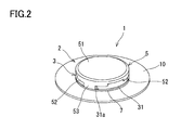
- FIG. 2 is a perspective view of the ventilation unit of FIG. 1 .
- FIG. 3 is a cross-sectional view of the ventilation unit of FIG. 1 .
- FIG. 4 is a bottom view of a cover component.
- FIG. 5 is a cross-sectional view of a ventilation unit according to an example of modification.
- FIG. 6A is a perspective view of a conventional ventilation member
- FIG. 6B is a cross-sectional view of the ventilation member.
- FIG. 7A is an exploded perspective view of a conventional ventilation structure
- FIG. 7B is a cross-sectional view of the ventilation structure.
- FIGS. 1 to 3 A ventilation unit 1 according to an embodiment of the present invention is shown in FIGS. 1 to 3 .
- the ventilation unit 1 includes: a ventilation member 2 configured to be attached to an opening 11 of a housing 10 ; a sealing member 6 configured to seal a gap between the housing 10 and the ventilation member 2 ; and a ring-shaped washer 7 surrounding the sealing member 6 .
- the direction in which the opening 11 opens is not particularly limited, and may be, for example, any of a vertically upward direction, a vertically downward direction, a horizontal direction, etc.
- the direction in which the opening 11 opens (a direction toward the upper side in FIG. 3 ) may be referred to as an upward direction
- the opposite direction (a direction toward the lower side in FIG. 3 ) may be referred to as a downward direction.
- the opening 11 is formed by burring of a thin plate that is a constituent material of the housing 10 . That is, the opening 11 has a diameter decreasing from the outside of the housing 10 toward the inside of the housing 10 .
- the opening 11 is not limited to such an opening.
- the opening 11 may be a straight hole formed in a thick plate that is a constituent material of the housing 10 .
- the ventilation member 2 includes: a water-proof gas-permeable membrane 4 for covering the opening 11 of the housing 10 ; a support 3 supporting the water-proof gas-permeable membrane 4 and configured to be fixed to the housing 10 ; and a cover component 5 covering the water-proof gas-permeable membrane 4 .
- the water-proof gas-permeable membrane 4 may be any membrane that allows permeation of gases and that blocks permeation of liquids (e.g., a woven fabric, a non-woven fabric, a mesh, or a net, which is made of resin or metal), and the structure and material of the water-proof gas-permeable membrane 4 are not particularly limited.
- the water-proof gas-permeable membrane 4 may have a configuration in which a reinforcing layer is laminated on a resin porous membrane. By providing a reinforcing layer, the water-proof gas-permeable membrane 4 of high strength can be obtained.
- a fluororesin porous body or a polyolefin porous body that can be produced by a commonly-known stretching method or extraction method is usable as the material of the resin porous membrane.
- the fluororesin include PTFE (polytetrafluoroethylene), polychlorotrifluoroethylene, tetrafluoroethylene-hexafluoropropylene copolymer, and tetrafluoroethylene-ethylene copolymer.
- monomers constituting the polyolefin include ethylene, propylene, and 4-methylpentene-1,1-butene.
- a polyolefin obtained by polymerization of any one of these monomers or a polyolefin obtained by copolymerization of these monomers can be used.
- a nanofiber film porous body for which polyacrylonitrile, nylon, or polylactic acid is used can be used.
- the resin porous membrane may be subjected to liquid-repellent treatment.
- the liquid-repellent treatment can be performed by applying a substance with low surface tension to the resin porous membrane, drying the substance, and then curing the substance.
- the liquid-repellent agent used for the liquid-repellent treatment may be any agent that allows formation of a coating having a lower surface tension than the resin porous membrane.
- a liquid-repellent agent containing a polymer having a perfluoroalkyl group is suitable.
- the application of a liquid-repellent agent can be performed by impregnation, spraying, or the like.
- the average pore diameter of the resin porous membrane is desirably 0.01 ⁇ m or more and 10 ⁇ m or less.
- a material having better gas permeability than the resin porous membrane is preferably used as the material of the reinforcing layer.
- a woven fabric, a non-woven fabric, a mesh, a net, a sponge, a foam, or a porous body, which is made of resin or metal can be used.
- Examples of the method for joining together the resin porous membrane and the reinforcing layer include adhesive lamination, thermal lamination, heat welding, ultrasonic welding, and bonding using an adhesive.
- the thickness of the water-proof gas-permeable membrane 4 be adjusted, for example, within a range of 1 ⁇ m to 5 mm, in view of the strength and the ease of fixing to the support 3 .
- the gas permeability of the resin porous membrane or the water-proof gas-permeable membrane 4 is preferably 0.1 to 300 sec/100 mL in terms of Gurley value.
- the support 3 is provided with an inner gas channel 21 configured to allow the water-proof gas-permeable membrane 4 to communicate with the internal space of the housing 10 .
- the support 3 has a tubular shape as a whole, and includes: a flange portion 31 having an upper surface to which the water-proof gas-permeable membrane 4 is adhered; and an insertion portion 32 projecting from an under surface of the flange portion 31 and configured to be inserted into the opening 11 of the housing 10 .
- the peripheral portion of the upper surface of the flange portion 31 is tapered so that the diameter increases toward the under surface of the flange portion 31 .
- a plurality of (in the example of the figure, three) engaging pieces that are radially elastically deformable are formed in the insertion portion 32 by making a plurality of cuts from the lower end of the lower portion of the insertion portion 32 .
- a claw 33 projecting radially outwardly is provided at the lower end of each of these engaging pieces, and the claw 33 is engaged with the opening-surrounding portion of the housing 10 .
- the cover component 5 forms an outer gas channel 22 opening radially outwardly between the cover component 5 and the water-proof gas-permeable membrane 4 and between the cover component 5 and the support 3 .
- the cover component 5 includes: a principal wall 51 facing the waterproof gas-permeable membrane 4 ; and a plurality of (in the example of the figure, three) hanging walls 52 hanging downwardly from a peripheral portion of the principal wall 51 .
- the diameter of the principal wall 51 is set equal to the outer diameter of the flange portion 31 of the support 3 .
- each hanging wall 52 is arranged at regular angular intervals, and each hanging wall 52 has a shape of an arc extending along the peripheral portion of the principal wall 51 .
- Each hanging wall 52 extends from the under surface of the principal wall 51 beyond the water-proof gas-permeable membrane 4 , and the end of the hanging wall 52 is located downwardly of the flat portion of the upper surface of the flange portion 31 .
- the inner portion of the end of each hanging wall 52 is tapered so that a large space is secured between the inner portion and the tapered surface of the flange portion 31 .
- a coupling piece 53 is provided at the center of each hanging wall 52 , and extends from the lower end of the hanging wall 52 to the under surface of the flange portion 31 .
- recesses 31 a which open radially outwardly and with which the coupling pieces 53 can be engaged are provided in the flange portion 31 at positions corresponding to the coupling pieces 53 .
- a claw projecting radially inwardly is provided at the end of each coupling piece 53 , and the claw is engaged with a stepped portion provided in the recess 31 a , so that the cover component 5 is coupled to the support 3 .
- the outer surfaces of the coupling pieces 53 and the edge surface of the flange portion 31 form a single cylindrical surface as shown in FIG. 2 .
- a plurality of (in the example of the figure, three) arc-shaped inner walls 54 are provided on the under surface of the principal wall 51 in such a manner that a circle defined by the inner walls 54 is smaller than a circle defined by the hanging walls 52 .
- the inner walls 54 are in contact with the flat portion of the upper surface of the flange portion 31 , and a space is thus secured between the water-proof gas-permeable membrane 4 and the principal wall 51 .
- the inner walls 54 are located radially inwardly of the hanging walls 52 , and cover the clearances between the hanging walls 52 so as to hide the water-proof gas-permeable membrane 4 from the outside.
- the hanging walls 52 and the inner walls 54 form a labyrinth in the vicinity of the opening of the outer gas channel 22 so as to prevent the waterproof gas-permeable membrane 4 from being exposed directly to the outside through the outer gas channel 22 .
- the sealing member 6 mentioned above is mounted around the root portion of the insertion portion 32 of the support 3 .
- the sealing member 6 seals a gap between the ventilation member 2 and the housing 10 by being pressed against the housing 10 by the flange portion 31 .
- An O-ring, a packing, or the like, can be used as the sealing member 6 .
- the washer 7 is pressed against the housing 10 by the ventilation member 2 around the sealing member 6 . That is, the washer 7 has a thickness greater than the distance by which a peripheral portion of the ventilation member 2 attached to the opening 11 of the housing 10 is spaced from the housing 10 .
- the inner diameter of the washer 7 is not particularly limited as long as the washer 7 does not interfere with the sealing member 6 .
- the outer diameter of the washer 7 is set equal to the outer diameter of the flange portion 31 of the support 3 in the present embodiment.
- the outer diameter of the washer 7 may be larger or smaller than the outer diameter of the flange portion 31 .
- the washer 7 may be formed of a hard material such as a plastic and a metal, but is preferably formed of an elastic material such as a rubber. Furthermore, an elastic material having heat resistance and weather resistance, such as a silicone rubber, is preferable.
- the hardness (Shore A hardness) of the washer 7 is preferably 30 to 70.
- the washer 7 serves as a stopper for restricting the displacement of the ventilation member 2 . Therefore, the ventilation member 2 or the housing 10 can be prevented from being broken due to too tight pressing.
- the water-proof gas-permeable membrane 4 is not exposed directly to the outside by virtue of the hanging walls 52 and the inner walls 54 of the cover component 5 . Accordingly, for example, the water-proof gas-permeable membrane 4 is not directly subjected to a jet of high-pressure water, and breakage of the water-proof gas-permeable membrane 4 can be prevented.
Landscapes
- Engineering & Computer Science (AREA)
- Microelectronics & Electronic Packaging (AREA)
- Chemical & Material Sciences (AREA)
- Chemical Kinetics & Catalysis (AREA)
- Casings For Electric Apparatus (AREA)
Applications Claiming Priority (3)
| Application Number | Priority Date | Filing Date | Title |
|---|---|---|---|
| JP2011099880A JP5714403B2 (ja) | 2011-04-27 | 2011-04-27 | 通気ユニット |
| JP2011-099880 | 2011-04-27 | ||
| PCT/JP2012/000081 WO2012147241A1 (ja) | 2011-04-27 | 2012-01-10 | 通気ユニット |
Publications (2)
| Publication Number | Publication Date |
|---|---|
| US20140047981A1 US20140047981A1 (en) | 2014-02-20 |
| US9120060B2 true US9120060B2 (en) | 2015-09-01 |
Family
ID=47071777
Family Applications (1)
| Application Number | Title | Priority Date | Filing Date |
|---|---|---|---|
| US14/113,525 Active 2032-03-13 US9120060B2 (en) | 2011-04-27 | 2012-01-10 | Ventilation unit |
Country Status (6)
| Country | Link |
|---|---|
| US (1) | US9120060B2 (de) |
| EP (1) | EP2704543B1 (de) |
| JP (1) | JP5714403B2 (de) |
| KR (1) | KR101958035B1 (de) |
| CN (1) | CN103503588B (de) |
| WO (1) | WO2012147241A1 (de) |
Cited By (3)
| Publication number | Priority date | Publication date | Assignee | Title |
|---|---|---|---|---|
| US20180097214A1 (en) * | 2016-10-04 | 2018-04-05 | Kabushiki Kaisha Toshiba | Pressure relief mechanism, case, and pressure relief valve |
| US20190331312A1 (en) * | 2018-04-25 | 2019-10-31 | Jute Industrial Co., Ltd. | Breathable element for lighting of vehicle |
| US20210010655A1 (en) * | 2018-02-20 | 2021-01-14 | Amogreentech Co., Ltd. | Ventilation cap |
Families Citing this family (15)
| Publication number | Priority date | Publication date | Assignee | Title |
|---|---|---|---|---|
| US9199191B2 (en) * | 2012-08-17 | 2015-12-01 | Ube Industries, Ltd. | Gas separation membrane module and method of replacing a hollow fiber element |
| JP6130183B2 (ja) * | 2013-03-26 | 2017-05-17 | 日東電工株式会社 | 通気部材 |
| JP6150578B2 (ja) | 2013-03-26 | 2017-06-21 | 日東電工株式会社 | 通気部材 |
| EP2842714B1 (de) * | 2013-08-16 | 2018-05-16 | Oxyphen AG | Druckausgleichselement |
| JP2015170469A (ja) * | 2014-03-06 | 2015-09-28 | 日東電工株式会社 | 気体透過部材及び通気性容器 |
| DE102015214923B4 (de) * | 2015-08-05 | 2019-02-14 | Continental Automotive Gmbh | Druckausgleichselement und Gehäuse mit einem solchen |
| EP3302011A1 (de) * | 2016-09-29 | 2018-04-04 | Continental Automotive GmbH | Elektronikbaugruppe mit einem gehäuse und einem druckausgleichskanal |
| TWI677273B (zh) * | 2018-01-18 | 2019-11-11 | 飛宏科技股份有限公司 | 用於防止水滲入電子產品之防水結構及防水環形圈 |
| BR112021006494A2 (pt) | 2018-10-11 | 2021-07-06 | Nitto Denko Corp | conjunto de ventilação e revestimento de ventilação |
| JP7378967B2 (ja) | 2019-06-07 | 2023-11-14 | 日東電工株式会社 | 通気部品 |
| CN114557146A (zh) | 2019-12-09 | 2022-05-27 | 日东电工株式会社 | 通气部件 |
| DE102020119593A1 (de) | 2020-07-24 | 2022-01-27 | Elringklinger Ag | Gehäuseelement, Kombination aus einem Druckausgleichselement und einem Gehäuseelement und Verfahren zum Herstellen einer solchen Kombination |
| JP7396235B2 (ja) | 2020-08-31 | 2023-12-12 | 株式会社デンソー | 電子装置 |
| CN114554743B (zh) * | 2020-11-27 | 2023-10-03 | 北京亿华通科技股份有限公司 | 一种防水透气装置以及电器设备 |
| TWI815651B (zh) * | 2022-09-12 | 2023-09-11 | 英業達股份有限公司 | 具有防水卸壓結構之電子裝置機殼 |
Citations (20)
| Publication number | Priority date | Publication date | Assignee | Title |
|---|---|---|---|---|
| JPH01161507U (de) | 1988-04-30 | 1989-11-09 | ||
| JPH043307U (de) | 1990-04-24 | 1992-01-13 | ||
| JPH0443307U (de) | 1990-08-17 | 1992-04-13 | ||
| JPH09135085A (ja) | 1995-11-09 | 1997-05-20 | Fujitsu Ten Ltd | ケースの防水構造 |
| US5891223A (en) * | 1997-08-20 | 1999-04-06 | Ultratech International, Inc. | Multi-stage vent filter |
| US20020066370A1 (en) * | 2000-12-06 | 2002-06-06 | Franco Goglio | Selective degassing valve for containers of aromatic or odorous products, such as coffee and the like |
| US6524361B1 (en) * | 2000-10-26 | 2003-02-25 | Hubbell Incorporated | Micro-porous filter |
| JP2004047425A (ja) | 2002-05-15 | 2004-02-12 | Nitto Denko Corp | 通気部材、これを用いた通気筐体、通気部材の抜け防止具および通気構造形成キット |
| JP2004090875A (ja) | 2002-09-03 | 2004-03-25 | Denso Corp | 車載用電子制御装置 |
| WO2006011496A1 (ja) | 2004-07-29 | 2006-02-02 | Matsushita Electric Industrial Co., Ltd. | 電子装置 |
| US20060054019A1 (en) | 2004-09-11 | 2006-03-16 | Mitsubishi Denki Kabushiki Kaisha | Electronic control apparatus |
| JP2007048585A (ja) | 2005-08-10 | 2007-02-22 | Nitto Denko Corp | 筐体の通気構造 |
| JP2007087666A (ja) | 2005-09-20 | 2007-04-05 | Nitto Denko Corp | 通気部材及び通気構造 |
| JP2007141959A (ja) | 2005-11-15 | 2007-06-07 | Hitachi Ltd | 電子制御装置および防水ケース |
| JP2010012842A (ja) | 2008-07-02 | 2010-01-21 | Hitachi Ltd | 電子制御装置 |
| JP2010052701A (ja) | 2008-08-29 | 2010-03-11 | Hitachi Automotive Systems Ltd | 電子制御装置 |
| US7678169B1 (en) * | 2006-07-12 | 2010-03-16 | Cummins Filtration Ip Inc. | Oil fill cap with air/oil separator |
| JP2010267538A (ja) | 2009-05-15 | 2010-11-25 | Nitto Denko Corp | 通気部材および通気構造 |
| US8246726B2 (en) * | 2008-04-04 | 2012-08-21 | Nitto Denko Corporation | Ventilation member |
| US8814993B2 (en) * | 2011-05-19 | 2014-08-26 | Nitto Denko Corporation | Vent structure |
Family Cites Families (6)
| Publication number | Priority date | Publication date | Assignee | Title |
|---|---|---|---|---|
| JPH0443307A (ja) * | 1990-06-11 | 1992-02-13 | Toray Ind Inc | シート状光導体の製造用口金 |
| JPH0727702Y2 (ja) * | 1990-09-21 | 1995-06-21 | 新日本無線株式会社 | 衛星放送受信用周波数変換器 |
| JPH0550136U (ja) * | 1991-12-13 | 1993-07-02 | シャープ株式会社 | ビス止め部防水構造 |
| CN201114187Y (zh) * | 2007-04-18 | 2008-09-10 | 青岛海信移动通信技术股份有限公司 | 手机来电显示灯处的防水装置 |
| KR101411762B1 (ko) * | 2008-12-31 | 2014-06-25 | 더블유.엘.고어 앤드 어소시에이츠 게엠베하 | 배기 장치 |
| JP5714402B2 (ja) * | 2011-04-27 | 2015-05-07 | 日東電工株式会社 | 通気ユニット |
-
2011
- 2011-04-27 JP JP2011099880A patent/JP5714403B2/ja active Active
-
2012
- 2012-01-10 EP EP12776889.3A patent/EP2704543B1/de active Active
- 2012-01-10 WO PCT/JP2012/000081 patent/WO2012147241A1/ja active Application Filing
- 2012-01-10 KR KR1020137031011A patent/KR101958035B1/ko active IP Right Grant
- 2012-01-10 US US14/113,525 patent/US9120060B2/en active Active
- 2012-01-10 CN CN201280020903.5A patent/CN103503588B/zh active Active
Patent Citations (24)
| Publication number | Priority date | Publication date | Assignee | Title |
|---|---|---|---|---|
| JPH01161507U (de) | 1988-04-30 | 1989-11-09 | ||
| JPH043307U (de) | 1990-04-24 | 1992-01-13 | ||
| JPH0443307U (de) | 1990-08-17 | 1992-04-13 | ||
| JPH09135085A (ja) | 1995-11-09 | 1997-05-20 | Fujitsu Ten Ltd | ケースの防水構造 |
| US5891223A (en) * | 1997-08-20 | 1999-04-06 | Ultratech International, Inc. | Multi-stage vent filter |
| US6524361B1 (en) * | 2000-10-26 | 2003-02-25 | Hubbell Incorporated | Micro-porous filter |
| US20020066370A1 (en) * | 2000-12-06 | 2002-06-06 | Franco Goglio | Selective degassing valve for containers of aromatic or odorous products, such as coffee and the like |
| JP2004047425A (ja) | 2002-05-15 | 2004-02-12 | Nitto Denko Corp | 通気部材、これを用いた通気筐体、通気部材の抜け防止具および通気構造形成キット |
| US6994621B2 (en) | 2002-05-15 | 2006-02-07 | Nitto Denko Corporation | Ventilation member, vented housing using the same, pull-out prevention member for ventilation member and kit for forming ventilation structure |
| JP2004090875A (ja) | 2002-09-03 | 2004-03-25 | Denso Corp | 車載用電子制御装置 |
| US20080041624A1 (en) | 2004-07-29 | 2008-02-21 | Matsushita Electric Industrial Co., Ltd. | Electronic Apparatus |
| WO2006011496A1 (ja) | 2004-07-29 | 2006-02-02 | Matsushita Electric Industrial Co., Ltd. | 電子装置 |
| US20060054019A1 (en) | 2004-09-11 | 2006-03-16 | Mitsubishi Denki Kabushiki Kaisha | Electronic control apparatus |
| JP2006135250A (ja) | 2004-11-09 | 2006-05-25 | Mitsubishi Electric Corp | 電子制御機器 |
| JP2007048585A (ja) | 2005-08-10 | 2007-02-22 | Nitto Denko Corp | 筐体の通気構造 |
| JP2007087666A (ja) | 2005-09-20 | 2007-04-05 | Nitto Denko Corp | 通気部材及び通気構造 |
| JP2007141959A (ja) | 2005-11-15 | 2007-06-07 | Hitachi Ltd | 電子制御装置および防水ケース |
| US7936566B2 (en) | 2005-11-15 | 2011-05-03 | Hitachi, Ltd. | Electronic control unit and waterproof case |
| US7678169B1 (en) * | 2006-07-12 | 2010-03-16 | Cummins Filtration Ip Inc. | Oil fill cap with air/oil separator |
| US8246726B2 (en) * | 2008-04-04 | 2012-08-21 | Nitto Denko Corporation | Ventilation member |
| JP2010012842A (ja) | 2008-07-02 | 2010-01-21 | Hitachi Ltd | 電子制御装置 |
| JP2010052701A (ja) | 2008-08-29 | 2010-03-11 | Hitachi Automotive Systems Ltd | 電子制御装置 |
| JP2010267538A (ja) | 2009-05-15 | 2010-11-25 | Nitto Denko Corp | 通気部材および通気構造 |
| US8814993B2 (en) * | 2011-05-19 | 2014-08-26 | Nitto Denko Corporation | Vent structure |
Cited By (6)
| Publication number | Priority date | Publication date | Assignee | Title |
|---|---|---|---|---|
| US20180097214A1 (en) * | 2016-10-04 | 2018-04-05 | Kabushiki Kaisha Toshiba | Pressure relief mechanism, case, and pressure relief valve |
| US10529969B2 (en) * | 2016-10-04 | 2020-01-07 | Kabushiki Kaisha Toshiba | Pressure relief mechanism, case, and pressure relief valve |
| US11264672B2 (en) | 2016-10-04 | 2022-03-01 | Kabushiki Kaisha Toshiba | Pressure relief mechanism, case, and pressure relief valve |
| US20210010655A1 (en) * | 2018-02-20 | 2021-01-14 | Amogreentech Co., Ltd. | Ventilation cap |
| US11892140B2 (en) * | 2018-02-20 | 2024-02-06 | Amogreentech Co., Ltd. | Ventilation cap |
| US20190331312A1 (en) * | 2018-04-25 | 2019-10-31 | Jute Industrial Co., Ltd. | Breathable element for lighting of vehicle |
Also Published As
| Publication number | Publication date |
|---|---|
| US20140047981A1 (en) | 2014-02-20 |
| EP2704543A1 (de) | 2014-03-05 |
| KR101958035B1 (ko) | 2019-03-13 |
| EP2704543A4 (de) | 2015-08-12 |
| JP5714403B2 (ja) | 2015-05-07 |
| WO2012147241A1 (ja) | 2012-11-01 |
| EP2704543B1 (de) | 2017-08-30 |
| CN103503588A (zh) | 2014-01-08 |
| CN103503588B (zh) | 2016-10-19 |
| KR20140026518A (ko) | 2014-03-05 |
| JP2012231089A (ja) | 2012-11-22 |
Similar Documents
| Publication | Publication Date | Title |
|---|---|---|
| US9120060B2 (en) | Ventilation unit | |
| US9120059B2 (en) | Ventilation unit | |
| US8814993B2 (en) | Vent structure | |
| US8246726B2 (en) | Ventilation member | |
| US9121626B2 (en) | Ventilation member | |
| US9528622B2 (en) | Ventilation member | |
| US9052119B2 (en) | Ventilation member | |
| US9242198B2 (en) | Ventilation member | |
| JP6132615B2 (ja) | 通気部材 | |
| JP2012230983A (ja) | 通気部材 | |
| JP5710359B2 (ja) | 通気部材 | |
| JP6121210B2 (ja) | 通気部材 |
Legal Events
| Date | Code | Title | Description |
|---|---|---|---|
| AS | Assignment |
Owner name: NITTO DENKO CORPORATION, JAPAN Free format text: ASSIGNMENT OF ASSIGNORS INTEREST;ASSIGNORS:UEMURA, KOU;YANO, YOUZOU;DAIMON, ATSUSHI;REEL/FRAME:031463/0051 Effective date: 20131010 |
|
| STCF | Information on status: patent grant |
Free format text: PATENTED CASE |
|
| MAFP | Maintenance fee payment |
Free format text: PAYMENT OF MAINTENANCE FEE, 4TH YEAR, LARGE ENTITY (ORIGINAL EVENT CODE: M1551); ENTITY STATUS OF PATENT OWNER: LARGE ENTITY Year of fee payment: 4 |
|
| MAFP | Maintenance fee payment |
Free format text: PAYMENT OF MAINTENANCE FEE, 8TH YEAR, LARGE ENTITY (ORIGINAL EVENT CODE: M1552); ENTITY STATUS OF PATENT OWNER: LARGE ENTITY Year of fee payment: 8 |