US9028107B2 - Lamp, reflector for a lamp and method for the production of the reflector - Google Patents
Lamp, reflector for a lamp and method for the production of the reflector Download PDFInfo
- Publication number
- US9028107B2 US9028107B2 US13/832,117 US201313832117A US9028107B2 US 9028107 B2 US9028107 B2 US 9028107B2 US 201313832117 A US201313832117 A US 201313832117A US 9028107 B2 US9028107 B2 US 9028107B2
- Authority
- US
- United States
- Prior art keywords
- reflector
- contact surface
- base
- led
- entry opening
- Prior art date
- Legal status (The legal status is an assumption and is not a legal conclusion. Google has not performed a legal analysis and makes no representation as to the accuracy of the status listed.)
- Active, expires
Links
- 238000000034 method Methods 0.000 title description 23
- 238000004519 manufacturing process Methods 0.000 title description 11
- 239000011521 glass Substances 0.000 claims description 9
- 230000036316 preload Effects 0.000 claims description 8
- 239000002241 glass-ceramic Substances 0.000 claims description 6
- 238000003801 milling Methods 0.000 description 10
- 238000003825 pressing Methods 0.000 description 9
- 230000003287 optical effect Effects 0.000 description 4
- 239000004065 semiconductor Substances 0.000 description 3
- 241000217377 Amblema plicata Species 0.000 description 2
- 230000015572 biosynthetic process Effects 0.000 description 2
- 238000001816 cooling Methods 0.000 description 2
- 230000009286 beneficial effect Effects 0.000 description 1
- 230000008878 coupling Effects 0.000 description 1
- 238000010168 coupling process Methods 0.000 description 1
- 238000005859 coupling reaction Methods 0.000 description 1
- 230000001419 dependent effect Effects 0.000 description 1
- 238000005553 drilling Methods 0.000 description 1
- 239000000428 dust Substances 0.000 description 1
- 230000000694 effects Effects 0.000 description 1
- 238000000227 grinding Methods 0.000 description 1
- 238000009499 grossing Methods 0.000 description 1
- 230000003760 hair shine Effects 0.000 description 1
- 238000007373 indentation Methods 0.000 description 1
- 238000003780 insertion Methods 0.000 description 1
- 230000037431 insertion Effects 0.000 description 1
- 230000001788 irregular Effects 0.000 description 1
- 238000000465 moulding Methods 0.000 description 1
- 230000001681 protective effect Effects 0.000 description 1
- 238000004080 punching Methods 0.000 description 1
- 229910052710 silicon Inorganic materials 0.000 description 1
- 239000010703 silicon Substances 0.000 description 1
Images


Classifications
-
- F—MECHANICAL ENGINEERING; LIGHTING; HEATING; WEAPONS; BLASTING
- F21—LIGHTING
- F21V—FUNCTIONAL FEATURES OR DETAILS OF LIGHTING DEVICES OR SYSTEMS THEREOF; STRUCTURAL COMBINATIONS OF LIGHTING DEVICES WITH OTHER ARTICLES, NOT OTHERWISE PROVIDED FOR
- F21V7/00—Reflectors for light sources
-
- C—CHEMISTRY; METALLURGY
- C03—GLASS; MINERAL OR SLAG WOOL
- C03B—MANUFACTURE, SHAPING, OR SUPPLEMENTARY PROCESSES
- C03B11/00—Pressing molten glass or performed glass reheated to equivalent low viscosity without blowing
- C03B11/06—Construction of plunger or mould
- C03B11/10—Construction of plunger or mould for making hollow or semi-hollow articles
-
- C—CHEMISTRY; METALLURGY
- C03—GLASS; MINERAL OR SLAG WOOL
- C03B—MANUFACTURE, SHAPING, OR SUPPLEMENTARY PROCESSES
- C03B21/00—Severing glass sheets, tubes or rods while still plastic
- C03B21/04—Severing glass sheets, tubes or rods while still plastic by punching out
-
- F—MECHANICAL ENGINEERING; LIGHTING; HEATING; WEAPONS; BLASTING
- F21—LIGHTING
- F21V—FUNCTIONAL FEATURES OR DETAILS OF LIGHTING DEVICES OR SYSTEMS THEREOF; STRUCTURAL COMBINATIONS OF LIGHTING DEVICES WITH OTHER ARTICLES, NOT OTHERWISE PROVIDED FOR
- F21V17/00—Fastening of component parts of lighting devices, e.g. shades, globes, refractors, reflectors, filters, screens, grids or protective cages
- F21V17/06—Fastening of component parts of lighting devices, e.g. shades, globes, refractors, reflectors, filters, screens, grids or protective cages the fastening being onto or by the lampholder
-
- F—MECHANICAL ENGINEERING; LIGHTING; HEATING; WEAPONS; BLASTING
- F21—LIGHTING
- F21V—FUNCTIONAL FEATURES OR DETAILS OF LIGHTING DEVICES OR SYSTEMS THEREOF; STRUCTURAL COMBINATIONS OF LIGHTING DEVICES WITH OTHER ARTICLES, NOT OTHERWISE PROVIDED FOR
- F21V17/00—Fastening of component parts of lighting devices, e.g. shades, globes, refractors, reflectors, filters, screens, grids or protective cages
- F21V17/10—Fastening of component parts of lighting devices, e.g. shades, globes, refractors, reflectors, filters, screens, grids or protective cages characterised by specific fastening means or way of fastening
- F21V17/14—Bayonet-type fastening
-
- F—MECHANICAL ENGINEERING; LIGHTING; HEATING; WEAPONS; BLASTING
- F21—LIGHTING
- F21V—FUNCTIONAL FEATURES OR DETAILS OF LIGHTING DEVICES OR SYSTEMS THEREOF; STRUCTURAL COMBINATIONS OF LIGHTING DEVICES WITH OTHER ARTICLES, NOT OTHERWISE PROVIDED FOR
- F21V17/00—Fastening of component parts of lighting devices, e.g. shades, globes, refractors, reflectors, filters, screens, grids or protective cages
- F21V17/10—Fastening of component parts of lighting devices, e.g. shades, globes, refractors, reflectors, filters, screens, grids or protective cages characterised by specific fastening means or way of fastening
- F21V17/16—Fastening of component parts of lighting devices, e.g. shades, globes, refractors, reflectors, filters, screens, grids or protective cages characterised by specific fastening means or way of fastening by deformation of parts; Snap action mounting
- F21V17/162—Fastening of component parts of lighting devices, e.g. shades, globes, refractors, reflectors, filters, screens, grids or protective cages characterised by specific fastening means or way of fastening by deformation of parts; Snap action mounting the parts being subjected to traction or compression, e.g. coil springs
-
- F—MECHANICAL ENGINEERING; LIGHTING; HEATING; WEAPONS; BLASTING
- F21—LIGHTING
- F21V—FUNCTIONAL FEATURES OR DETAILS OF LIGHTING DEVICES OR SYSTEMS THEREOF; STRUCTURAL COMBINATIONS OF LIGHTING DEVICES WITH OTHER ARTICLES, NOT OTHERWISE PROVIDED FOR
- F21V17/00—Fastening of component parts of lighting devices, e.g. shades, globes, refractors, reflectors, filters, screens, grids or protective cages
- F21V17/10—Fastening of component parts of lighting devices, e.g. shades, globes, refractors, reflectors, filters, screens, grids or protective cages characterised by specific fastening means or way of fastening
- F21V17/16—Fastening of component parts of lighting devices, e.g. shades, globes, refractors, reflectors, filters, screens, grids or protective cages characterised by specific fastening means or way of fastening by deformation of parts; Snap action mounting
- F21V17/164—Fastening of component parts of lighting devices, e.g. shades, globes, refractors, reflectors, filters, screens, grids or protective cages characterised by specific fastening means or way of fastening by deformation of parts; Snap action mounting the parts being subjected to bending, e.g. snap joints
-
- F—MECHANICAL ENGINEERING; LIGHTING; HEATING; WEAPONS; BLASTING
- F21—LIGHTING
- F21V—FUNCTIONAL FEATURES OR DETAILS OF LIGHTING DEVICES OR SYSTEMS THEREOF; STRUCTURAL COMBINATIONS OF LIGHTING DEVICES WITH OTHER ARTICLES, NOT OTHERWISE PROVIDED FOR
- F21V7/00—Reflectors for light sources
- F21V7/04—Optical design
- F21V7/048—Optical design with facets structure
-
- F—MECHANICAL ENGINEERING; LIGHTING; HEATING; WEAPONS; BLASTING
- F21—LIGHTING
- F21V—FUNCTIONAL FEATURES OR DETAILS OF LIGHTING DEVICES OR SYSTEMS THEREOF; STRUCTURAL COMBINATIONS OF LIGHTING DEVICES WITH OTHER ARTICLES, NOT OTHERWISE PROVIDED FOR
- F21V7/00—Reflectors for light sources
- F21V7/22—Reflectors for light sources characterised by materials, surface treatments or coatings, e.g. dichroic reflectors
- F21V7/24—Reflectors for light sources characterised by materials, surface treatments or coatings, e.g. dichroic reflectors characterised by the material
-
- F21Y2101/02—
-
- F—MECHANICAL ENGINEERING; LIGHTING; HEATING; WEAPONS; BLASTING
- F21—LIGHTING
- F21Y—INDEXING SCHEME ASSOCIATED WITH SUBCLASSES F21K, F21L, F21S and F21V, RELATING TO THE FORM OR THE KIND OF THE LIGHT SOURCES OR OF THE COLOUR OF THE LIGHT EMITTED
- F21Y2115/00—Light-generating elements of semiconductor light sources
- F21Y2115/10—Light-emitting diodes [LED]
Definitions
- the invention refers to a lamp with at least one LED, a base that is rigidly connected to the at least one LED and that has at least one base contact surface, as well as a reflector, which has at least one reflector contact surface, an entry opening and an exit opening, and a longitudinal direction that runs from the exit opening to the entry opening, the reflector being connectable to the base, and the at least one base contact surface abutting the at least one reflector contact surface, thus preventing a movement of the base and/or reflector towards each other when the reflector is connected to the base.
- the invention refers to a reflector for such a lamp and a method for the production of such a reflector.
- a lamp according to the preamble is provided with at least one LED that is mounted on an LED semiconductor chip, which is mounted on the base.
- this base acts as a connecting component between the actual LED or the LED semiconductor chip and the reflector of the lamp.
- the mounting of the two components on each other can be done with a clip connection, for example.
- the base comprises elastic clips, for example, which are bent open when the reflector is inserted and lock into purpose-made slits, holes or passages on the reflector body.
- the reflector itself comprises a longitudinal direction and an entry and exit opening, whereby the longitudinal direction of the reflector stretches from its entry opening to the exit opening.
- the exit opening is the opening through which the light emitted by the at least one LED leaves the reflector and hence the lamp.
- the longitudinal direction coincides with the optical axis and the axis of symmetry of the reflector and in this case, comprises the at least one LED.
- the reflector very often comprises an inner surface that can be faceted, for example, in order to achieve the desired light emission characteristic.
- the LED in the desired position as precisely as possible.
- this can be a focus of the ellipse.
- It may also be beneficial to arrange the LED slightly in front of or behind this focus.
- the at least one reflector contact surface and the at least one base contact surface are provided to ensure this exact positioning. Both lie on top of each other when the reflector is connected to the base and thus prevent a further movement of the two components on top of each other. It is therefore possible to achieve a reproducible, very defined and well known positioning of the two components relative to each other. If the at least one reflector contact surface and the at least one base contact surface are produced accurately, the extent to which the LED protrudes into the reflector can be defined and reproduced in a precise way. Furthermore, should the LED not be arranged in the interior space of the reflector, the exact positioning of the reflector relative to the base is important. This situation also concerns the positioning of the reflector relative to the LED, so that the light emitted by the LED that enters the reflector through the entry opening possesses the desired emission characteristics when it leaves the reflector through the exit opening.
- the reflector contact surface is conventionally the area directly around the entry opening of the reflector. In the connected state, this area of the reflector then preferably contacts the corresponding area of the base around the LED completely.
- a reflector for a lamp of this sort is conventionally pressed from glass or glass ceramic. To do this, a mould is initially filled with a desired amount of glass or glass ceramic and then pressed in this mould between two movable moulding dies until it has the desired contour. The reflector that has been produced by this method is actually already fitted with an exit opening, but not yet with an entry opening. This is produced in a preferred embodiment of a method of this sort by a so-called “hot punch” method, whereby a mandrel or pin is guided through the pressed reflector at the desired point.
- the glass reflector does not shatter during this method, it must be heated or the insertion of the pin must occur at such a speed that the reflector has not yet cooled following the pressing.
- this leads to a deformation of the reflector area that is located around the desired entry opening.
- this area forms the reflector contact surface, it must have a complex finish, for example sawn or milled. This is complicated and therefore expensive.
- the reflector contact surface that has been treated in this way must stand as exactly perpendicular as possible to the optical axis of the reflector, be as smooth as possible and be arranged precisely as possible at the correct height relative to the operation point of the reflector.
- the serration or milling for the finishing of the reflector contact surface must take place in a separate step of the procedure, the relation to the optically relevant points on the inner surface of the reflector is compulsorily lost and thus the exact location of the operation point.
- the entry opening could be created by, for example, milling in the reflector, rather than the “hot punch” method.
- milling in the reflector rather than the “hot punch” method.
- a complex post-treatment is unnecessary.
- the milling or drilling of the entry opening is time-consuming in comparison to the “hot punch” method and is therefore expensive.
- a separate tool must be used for milling, which adds to the above mentioned problems with production tolerance. Consequently this embodiment also has disadvantages.
- grooves or recesses can be made along the sides of the reflector neck, into which the structures on the base can lock into as precisely as possible. Serration or milling can also be used for this purpose. A backlash-free mounting could then also be achieved.
- the introduction of grooves or recesses into the pressed reflector creates a further step in the procedure and the resulting precision and tolerance problems.
- a simple and exact positioning of the reflector relative to the LED is thereby not possible.
- the WO 20121158404 A1 that was published after the filing date of the present application shows a reflector for a lamp whose reflector contact surface is arranged around the entry opening of the reflector. If the entry opening is made in the reflector body, the problems described occur as a result.
- EP 1 961 708 A1 a method is described to produce reflectors from glass, whereby the entry openings are created with the hot punch method in the reflector body.
- the part of the reflector body in which the entry openings are made is supported by a special holding device, so filament formation of the heated glass does not occur.
- US 2004/0264200 A1 also deals with a method for producing a reflector for a lamp, in which various possibilities are given for creating the entry opening in the reflector body.
- the lower area of the reflector body, in which the entry opening has been made must be submitted to a thermal post treatment.
- WO 2011/104 255 A1 a so-called downlight, i.e. a lamp that shines downwards, is described, whereby the reflector is only held by placing it on a mounting ring. There is no contact with the base on which the LEDs are arranged.
- the invention thus aims to propose a lamp whose reflector is adjustable relative to the LED with sufficient accuracy and which is simple, quick and cost-effective to produce. Furthermore, a corresponding reflector and a production method for such a reflector should be proposed.
- the invention solves the posed aim by means of a lamp according to the preamble which is characterized by the fact that the reflector is shaped in such a way that a projection of the at least one reflector contact surface in the longitudinal direction of the reflector is free of undercuts.
- the reflector starting from the reflector contact surface, there is no further part of the reflector in the longitudinal direction.
- the longitudinal direction runs from top to bottom.
- the at least one reflector contact surface would be the lowest part of the reflector in this arrangement.
- the at least one reflector contact surface is arranged in the longitudinal direction between the entry opening and the exit opening.
- the at least one reflector contact surface is therefore not a wall of a groove in the reflector.
- the at least one reflector contact surface in this arrangement of the reflector is visible in a vertical view from below.
- This arrangement of the at least one reflector has the advantage that the at least one reflector contact surface can be manufactured with a higher accuracy during a conventional pressing procedure. As a result, a second consequent step in the procedure is not needed to give the at least one reflector contact surface a post treatment using an expensive sawing or milling process, or to form it into the reflector. Moreover, the use of another tool for this purpose is superfluous, meaning that the production tolerances of the respective tools and steps in the procedure no longer add up, so that, in total, a more precise arrangement of the reflector and thus a more precise positioning of the reflector relative to the at least one LED in the lamp are possible.
- a circumferential ridge or several individual ridges can be arranged on an outer side of the reflector, for example, which each form a reflector contact surface.
- the reflector is then only positioned above the definite arrangement of this at least one reflector contact surface and the respective at least one base contact surface relative to the at least one LED.
- the form of the neck area of the reflector where the entry opening of the reflector is located is no longer important, as this neck area is no longer used to position the reflector relative to the at least one LED.
- this area could be irregularly shaped, sloping or otherwise, without affecting the positioning accuracy of the reflector relative to the LED.
- the entry opening in a reflector such as this can therefore be made particularly easily with the so-called hot punch method, as the deformation of the surfaces arranged around the entry opening is unproblematic.
- the lamp comprises preloading devices that preload the at least one reflector contact surface against the at least one base contact surface.
- These preloading devices are not necessary for the actual positioning of the reflector relative to the at least one LED, but ensure that the reflector does not move from the set position once it has been connected to the base.
- grooves or other mechanical holding elements can be located on the outer side of the reflector, for example. With the aid of these, the reflector is secured on the base, for example by clipping it on.
- These mechanical holding elements and the purpose-made structures are preferably situated on the ridges or the circumferential ridge on which the at least one reflector contact surface is also located.
- these structures are not found on the ridges themselves, but rather are mounted separately at a considerable distance on the outer surface of the reflector.
- the structures can be, for example, bulges, protrusions, indentations or grooves on the outer surface of the reflector, which can be brought into contact with the base using correspondingly designed mechanical counter-structures, which are found on the base.
- mount the reflector on the base in a particularly simple way, for example by snapping or clipping it in, or by means of a bayonet lock, for example.
- the reflector preferably comprises an outer surface that has at least one recess which the preloading devices lock into when the reflector is connected to the base.
- the preloading devices themselves do not have to be designed as one piece with the base, but can also be made as separate components. In this way it is conceivable, for example, to provide spring loaded pins on the base which lock into the purpose made recesses in the reflector when the reflector is correctly positioned relative to the base. They then exert a force on the reflector and preload the reflector contact surface against the base contact surface.
- the lamp comprises at least two reflector contact surfaces and at least two base contact surface. This ensures a simple and secure positioning of the reflector relative to the base, and thus to the LED which is rigidly connected to the base.
- the number and arrangement of the individual contact surfaces can be freely selected according to the relevant requirements.
- the reflector preferably has a length D along its longitudinal direction.
- a distance d between the at least one recess, which the preloading devices lock into and the entrance opening, has a value of less than one third of the length in the longitudinal direction D, preferably less than a quarter, and especially preferably less than one fifth. This ensures that the distances across which the preloading devices have to apply force to the reflector are small, in comparison to the length D of the reflector, so that a particularly high mechanical stability is achieved.
- the most precise positioning possible of the reflector relative to the at least one LED is thereby also ensured, if outside forces, such as bumps or hits, act on at least one of the components. In addition, the effect of longitudinal changes due to varying temperatures is minimized.
- the reflector is preferably produced in one piece made from glass or glass ceramic. This results in a particularly simple production, wherein a high speed production and low production costs can be achieved.
- the preloading devices lock into corresponding purpose-made recesses or grooves on the outer side of the reflector, it has been proven to be advantageous if the preloading devices only lie on one wall of the respective recess, so as not to arrange the system so that it is mechanically overdetermined, thereby affecting the exact positioning of the reflector relative to the at least one LED.
- the preloading devices lie on the wall of the recess via which they can exert a force on the reflector, which presses the at least one reflector contact surface and the at least one base contact surface against each other.
- a method according to the invention for producing a reflector of this sort comprises the steps:
- the special arrangement and alignment of the at least one reflector contact surface of a reflector for a lamp according to the invention means that the at least one reflector contact surface can be produced with the necessary precision and flatness in the pressing procedure.
- the entry opening can be made in the reflector without the reflector contact surface becoming deformed, so that a post-treatment of the reflector contact surface is not necessary.
- the creation of the entry opening preferably involves puncturing the reflector at an entry point with a pin. It is particularly preferable if a smoothing of the at least one reflector contact surface following pressing, especially using sawing, milling or grinding, is not necessary.
- the reflector base which is closed prior to pressing, is punctured by a pin when warm, directly after the pressing, or once it has been reheated after cooling down.
- the base of the reflector neck into which the entry opening is to be made, punctured and the desired hole created, but also the surrounding area around the reflector neck, which is generally circular, is greatly affected, as it is deformed by the puncture process.
- This deformation is not avoided in a method according to the invention, yet does not lead to problems, as the deformed area of the reflector neck is not used for the positioning of the reflector relative to the at least one LED.
- the reflector neck which may be deformed, that is opened with the entry opening, has no contact with the at least one LED or the LED chip carrying it. Therefore it is not dependent on the exact end contour of this section of the reflector neck.
- FIG. 1 a schematic section view through a lamp according to the prior art
- FIG. 2 an enlarged section from FIG. 1 ,
- FIG. 3 a reflector for a lamp from the prior art in a schematic 3D view
- FIG. 4 a schematic section display through a lamp according to a first embodiment of the present invention
- FIG. 5 an enlarged section from FIG. 4 ,
- FIG. 6 a reflector for a lamp according to an embodiment of the present invention in a schematic 3D view
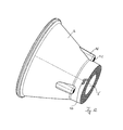
- FIG. 7 a reflector for a lamp according to a second embodiment of the present invention in a schematic 3D view
- FIG. 8 the schematic side view of a lamp according to a further embodiment of the present invention.
- FIG. 9 the schematic section display through a lamp according to a further embodiment of the present invention.
- FIG. 10 a reflector for a lamp according to a further embodiment of the present invention
- FIG. 11 a schematic partial view of a lamp according to an embodiment of the present invention.
- FIG. 12 a reflector for a lamp according to a further embodiment of the present invention in a schematic 3D view.
- FIG. 1 shows a schematic view display through a lamp according to the prior art.
- the lamp comprises a reflector 2 that has an exit opening 4 and an entry opening 6 , and which has facets 10 on a reflector inner side 8 .
- Unfaceted reflector inner sides 8 are of course also conceivable.
- the lamp comprises a base 12 onto which an LED 14 is arranged, which is depicted as a bump in FIG. 1 .
- This can refer to the actual LED 14 or an optical lens, which is located above the actual LED chip.
- a simple protective cover, made of silicon for example, located above the actual LED chip is also possible, which should protect the semiconductor chip from dust and moisture.
- Two holding elements 16 are arranged at the side of the base 12 , each with a preloading device at the upper end, with which they lock into purpose made grooves 20 on the reflector 2 .
- the reflector itself has a reflector contact surface 22 on its underside that surrounds the entry opening 6 and with which it abuts entirely the base contact surface 24 .
- the fact that the reflector contact surface 22 abuts the base contact surface 24 prevents a further movement of the reflector 2 and/or the base 12 .
- Both contact surfaces 22 , 24 are therefore responsible for the positioning of the reflector 2 relative to the LED 14 . Consequently, the reflector contact surface 22 , as well as the base contact surface 24 , must be made as precisely as possible.
- FIG. 2 shows an enlarged section from FIG. 1 , wherein it can again be recognized that the reflector contact surface 22 abuts the base contact surface 24 and is thus responsible for the positioning of the reflector 2 relative to the LED 14 .
- the preloading device 18 on the holding element 16 locks into the groove 20 and also lies on top of the reflector 2 . However, this does not prevent a movement of the reflector 2 onto the base 12 , rather it only applies a preload force on the reflector 2 .
- the at least one reflector contact surface 22 and the at least one base contact surface 24 are pressed against each other by this preload force. To do this, the groove 20 and, for example, the length of the holding element 16 do not have to be made as precisely as the reflector contact surface 22 and the base contact surface 24 . It is only important that a preload force is exerted on the reflector 2 .
- the positioning of the reflector 2 relative to the LED 14 is not affected as a result.
- FIG. 3 shows the reflector 2 from FIGS. 1 and 2 in a schematic 3D view. It is possible the recognize the reflector contact surface 22 that surrounds the entry opening 6 .
- the reflector contact surface 22 has had a post treatment by milling or sawing in order to achieve the desired accuracy.
- the grooves 20 are inserted into purpose made ridges 26 on the reflector 2 .
- a further tolerance of the saw cut or the milling plane relative to the outer contour of the reflector 2 accompanies the tolerances of the actual pressing tools.
- FIG. 4 shows a lamp according to a first embodiment of the present invention. It is possible to recognize the exit opening 4 , the entry opening 6 and the inner side 8 of the reflector, onto which facets 10 are arranged.
- the LED 14 which is mounted on the base 12 , protrudes into the entry opening 6 .
- the reflector contact surface 22 is no longer arranged at the same height as the entry opening 6 , but in the longitudinal direction L between the entry opening and the exit opening 4 .
- the base contact surface 24 of the base 12 is also moved correspondingly.
- the reflector 2 comprises parts which are arranged further down than the reflector contact surface 22 , such as one of the bottom surfaces 28 surrounding the entry opening 6 .
- no other part of the reflector 2 is located directly underneath the reflector contact surface 22 .
- two ridges 26 are arranged on the reflector 2 , each comprising a groove 20 which the preloading devices 18 on the holding elements lock into. However, these only serve to exert a preload force on the reflector 2 and thus keep it in its position, as defined by the reflector surface 22 and the base contact surface 24 . These elements have no influence on the alignment of the reflector 2 relative to the LED 14 .
- a length D of the reflector 2 and a distance d are depicted in FIG. 4 , the latter being the distance between the groove 20 and the entry opening 6 . It can be seen that the distance d is small in comparison to the length D. This results in a high mechanical stability.
- the preloading device 18 and the holding elements 16 are shown in the form of hook elements. Of course other sorts of preloading devices 18 are conceivable.
- FIG. 5 shows an enlarged section from FIG. 4 .
- the expansion of the gap 30 between the bottom surface 28 and the base 12 is only determined by the reflector contact surface 22 and the base contact surface 24 , and not by the contact between the preloading device 18 and the one side of the groove 20 .
- the bottom surface 28 is not suitable for such an arrangement, it is depicted as wavy and slightly bevelled.
- FIG. 6 shows the reflector 2 from FIGS. 4 and 5 in a schematic 3D view.
- the irregularly shaped bottom surface 28 surrounding the entry opening 6 is not suitable for an exact positioning of the reflector 2 relative to the LED 14 of the base 12 , due to its irregular shape and contour.
- the reflector contact surfaces 22 on the under side of the ridges 26 are intended for this purpose.
- the grooves 20 which the preloading devices 18 can lock into, are again located in the ridges 26 .
- the preloading device 18 and the groove 20 on a side panel of the groove 20 preferably only come into contact in order to avoid the system being overdetermined.
- FIG. 7 shows the reflector 2 for a further embodiment of the present invention in a schematic 3D view.
- the bottom surface 28 surrounds the entry opening 6 of the reflector 2 .
- the reflector 2 shown in FIG. 7 has a circumferential reflector contact surface 22 , by means of which the reflector 2 can be connected to the relevant base 12 in every angle alignment.
- the reflector 2 does not have individual ridges 26 , but a circumferential bulge 32 . This can also be perceived as an individual circumferential ridge, into which the now circumferential groove 20 is inserted, which the preloading devices 18 arranged on the base 12 can lock into.
- the reflector contact surface 22 On the underside of the bulge is the even and smoothly pressed reflector contact surface 22 .
- the base 12 also comprise a circumferential base contact surface 24 , the reflector contact surface 22 lies entirely on top of this base contact surface 24 .
- the two contact surfaces 22 , 24 can also be brought into contact section by section only.
- this reflector contact surface 22 shown in FIG. 7 is arranged in the longitudinal direction L of the reflector between the entry opening 6 and the exit opening 4 , this reflector contact surface 22 is not affected if the hot punch method is to be carried out, during which the entry opening 6 is made in the bottom surface 28 .
- no other component of the reflector 2 is located directly below the reflector contact surface 22 in the longitudinal direction L, so that the projection of the at least one reflector contact surface 22 in the longitudinal direction L of the reflector 2 is free of undercuts.
- FIG. 8 shows the reflector 2 from FIG. 7 in a schematic side view, in connection with the base 12 .
- the ring-shaped bottom surface 28 can be seen, whose contour is irrelevant for the positioning of the reflector 2 .
- the circumferential groove 20 can be recognized, which the preloading devices 18 arranged on the holding elements 16 lock into. All other forms of known preloading devices 18 are of course also conceivable here. This can be, for example, a number of mounted hooks distributed across the area that are arranged at certain distances on the base 12 and lock into the ring-shaped groove 20 . Of course, the groove 20 does not have to be completely circumferential.
- preloading devices 18 are provided, which should lock into the groove 20 .
- the rotation symmetry of the reflector 2 and the base 12 suggested in FIG. 8 is only preferable, but not necessary for the present invention.
- the gap 30 between the bottom surface 28 and the base 12 can also be clearly recognized.
- the contact here between the preloading devices 18 and the groove 20 is not crucial for the positioning of the reflector relative to the LED; it only holds the reflector in its position as defined by the reflector contact surface 22 and the base contact surface 24 .
- FIG. 9 shows a schematic view display through a lamp according to a further embodiment of the present invention.
- the preloading devices 18 are no longer designed to be in one piece with the base 12 . It refers much more to pins 34 that are stored spring-loaded by spring elements 38 in purpose made holes 36 . Should the reflector 2 be inserted from above, the pins 34 are pushed outwards against the spring elements 38 and do not snap back into place until the pins 34 can lock into purpose made recesses 40 . However, this also only causes a preload, so that a force is exerted on the reflector 2 . The at least one reflector contact surface 22 and the at least one base contact surface 24 are pushed against each other by this force. In FIG.
- the pins 34 do not lock into the recesses 40 centrally, rather they only lie on top of one—the lower-panel of the recess 40 and thus exert the force on the reflector 2 .
- the actual positioning of the reflector 2 relative to the LED 14 is done by the reflector contact surface 22 , now arranged above the preloading devices 18 , and the corresponding base contact surface 24 .
- the recesses 40 for the pins 34 are located lower down in the embodiment shown, i.e. in the longitudinal direction between the entry opening 6 and the reflector contact surface 22 , no other part of the reflector 2 is arranged directly below the individual reflector contact surfaces 22 , so that here, a projection of the at least one reflector contact surface 22 in the longitudinal direction L of the reflector is also free of undercuts.
- FIG. 10 shows the reflector from FIG. 9 in a schematic 3D view.
- the reflector 2 has three ridges 26 , two of which are shown. In each case, the ridges are arranged 120° displaced from each other on the outside of the reflector 2 .
- On their underside are the reflector contact surfaces 22 , which have been pressed smooth.
- On the reflector neck are the recesses 40 which the pins 34 shown in FIG. 9 , acting as preloading devices 18 , can lock into.
- the bottom surface 28 is also irrelevant for the positioning of the reflector 2 relative to the LED 14 .
- FIG. 11 shows the reflector 2 from FIG. 10 , which is connected to the base 12 .
- the base 12 On the base 12 , one of the holes 36 can be recognized, into which a pin 34 is guided, acting as a preloading device 18 .
- the reflector 2 has three ridges 26 , each provided with a reflector contact surface 22 .
- the base 12 has one circumferential base contact surface 24 .
- a base contact surface 24 is only provided in the areas in which there is also a reflector contact surface 22 . This can result in recesses which, from a thermal perspective, can be useful for cooling the arrangement, for example. In this case the heat generated by the LED 14 does not have to leave the reflector 2 through the exit opening 4 , but can escape through the entry opening 6 and the gap 30 between the reflector 2 and the base 12 .
- FIG. 12 shows a schematic view of the reflector 2 for a further embodiment of the present invention.
- the difference to the reflector 2 depicted thus far is in a notch 42 , which the purpose made pin element on the base 12 can lock into.
- the reflector 2 can of course have several of these notches 42 , which are distributed equidistantly across the area.
- the corresponding pin elements on the base 12 lock into the notches 42 so that the two components are connected with each other in the same way as a bayonet lock and can be preloaded.
- the notch 42 is also located in a reflector neck, which is situated lower than the reflector contact surface 22 , i.e. more towards the entry opening 6 . Nevertheless, there is no reflector part located directly below this reflector contact surface 22 , i.e. within the projection in the longitudinal direction L of the reflector 2 , so that this projection is also free of undercuts.
Landscapes
- Engineering & Computer Science (AREA)
- General Engineering & Computer Science (AREA)
- Chemical & Material Sciences (AREA)
- Materials Engineering (AREA)
- Organic Chemistry (AREA)
- Manufacturing & Machinery (AREA)
- Fastening Of Light Sources Or Lamp Holders (AREA)
- Securing Globes, Refractors, Reflectors Or The Like (AREA)
- Non-Portable Lighting Devices Or Systems Thereof (AREA)
- Led Device Packages (AREA)
Applications Claiming Priority (3)
| Application Number | Priority Date | Filing Date | Title |
|---|---|---|---|
| DE102012009539 | 2012-03-29 | ||
| DE102012009539.2 | 2012-03-29 | ||
| DE102012009539.2A DE102012009539B4 (de) | 2012-03-29 | 2012-03-29 | Leuchte |
Publications (2)
| Publication Number | Publication Date |
|---|---|
| US20130258674A1 US20130258674A1 (en) | 2013-10-03 |
| US9028107B2 true US9028107B2 (en) | 2015-05-12 |
Family
ID=47901753
Family Applications (1)
| Application Number | Title | Priority Date | Filing Date |
|---|---|---|---|
| US13/832,117 Active 2033-03-29 US9028107B2 (en) | 2012-03-29 | 2013-03-15 | Lamp, reflector for a lamp and method for the production of the reflector |
Country Status (5)
| Country | Link |
|---|---|
| US (1) | US9028107B2 (de) |
| EP (1) | EP2644979A3 (de) |
| JP (1) | JP5951546B2 (de) |
| CN (1) | CN103363446B (de) |
| DE (1) | DE102012009539B4 (de) |
Cited By (1)
| Publication number | Priority date | Publication date | Assignee | Title |
|---|---|---|---|---|
| DE202016001576U1 (de) | 2016-03-09 | 2016-05-12 | Günther Rösch | Beweglicher Wehrständer zur Wasserabflussregulierung als Aufsatz für bestehende Wehre, insbesondere zur Stauhaltung bei Wasserkraftwerken |
Families Citing this family (8)
| Publication number | Priority date | Publication date | Assignee | Title |
|---|---|---|---|---|
| DE102014101403A1 (de) * | 2013-05-15 | 2014-11-20 | Seidel GmbH & Co. KG | Leuchtvorrichtung |
| WO2015156986A1 (en) * | 2014-04-07 | 2015-10-15 | 3M Innovative Properties Company | Light horn arrays for ducted lighting systems |
| KR101601531B1 (ko) * | 2014-11-07 | 2016-03-10 | 주식회사 지엘비젼 | 조명장치 |
| JPWO2017002267A1 (ja) * | 2015-07-02 | 2018-04-05 | パイオニア株式会社 | 光反射装置及び発光装置 |
| DE102016202571A1 (de) * | 2016-02-19 | 2017-08-24 | Osram Gmbh | Beleuchtungseinrichtung |
| JP2018069912A (ja) * | 2016-10-28 | 2018-05-10 | 三菱電機株式会社 | ドライバモニタリング装置 |
| US10655821B2 (en) | 2018-05-18 | 2020-05-19 | Lumileds Llc | LED device holder, LED lighting system, and method of manufacture |
| WO2024111079A1 (ja) * | 2022-11-24 | 2024-05-30 | 三菱電機株式会社 | 車室内撮影装置 |
Citations (13)
| Publication number | Priority date | Publication date | Assignee | Title |
|---|---|---|---|---|
| US3662165A (en) * | 1970-03-02 | 1972-05-09 | Gen Electric | Luminaire reflector |
| US3700882A (en) * | 1970-09-02 | 1972-10-24 | Jean Planchon | Faceted reflector |
| US4021659A (en) * | 1975-10-30 | 1977-05-03 | General Electric Company | Projector lamp reflector |
| US4447865A (en) * | 1982-05-13 | 1984-05-08 | General Electric Company | Reflector lamp |
| US6080464A (en) * | 1995-11-20 | 2000-06-27 | Heraeus Med Gmbh | Reflector for a radiating luminous source and use of the same |
| US20040264200A1 (en) | 2003-06-26 | 2004-12-30 | Asahi Techno Glass Corporation | Glass reflector for projector and manufacturing method for the same |
| US20080055912A1 (en) * | 2006-08-15 | 2008-03-06 | Schott Ag | Reflector for gas discharge lamps |
| EP1961708A1 (de) | 2007-01-24 | 2008-08-27 | Schott AG | Verfahren zur Herstellung von Reflektoren aus Glas oder Glaskeramik |
| US20110019409A1 (en) | 2009-07-21 | 2011-01-27 | Cooper Technologies Company | Interfacing a Light Emitting Diode (LED) Module to a Heat Sink Assembly, a Light Reflector and Electrical Circuits |
| DE102009047493A1 (de) | 2009-12-04 | 2011-06-09 | Osram Gesellschaft mit beschränkter Haftung | Leuchtvorrichtung und Aufsatzelement zur Befestigung an der Leuchtvorrichtung |
| WO2011104255A1 (de) | 2010-02-23 | 2011-09-01 | Zumtobel Lighting Gmbh | Rahmenloses downlight |
| DE102010031312A1 (de) | 2010-07-14 | 2012-01-19 | Osram Ag | Befestigungselement, Leuchtmodul und Leuchtvorrichtung |
| WO2012158404A1 (en) | 2011-05-13 | 2012-11-22 | Cooper Technologies Company | Reflectors and reflector attachments for use with light-emitting diode (led) light sources |
Family Cites Families (8)
| Publication number | Priority date | Publication date | Assignee | Title |
|---|---|---|---|---|
| JP2004093623A (ja) * | 2002-08-29 | 2004-03-25 | Olympus Corp | 照明装置及びそれを用いた表示装置 |
| WO2007049206A1 (en) * | 2005-10-26 | 2007-05-03 | Koninklijke Philips Electronics N.V. | Electric lamp/reflector unit with a moulded reflector |
| JP4565652B2 (ja) * | 2006-02-16 | 2010-10-20 | スタンレー電気株式会社 | Led照明灯具 |
| CN201034290Y (zh) * | 2007-04-06 | 2008-03-12 | 鹤山丽得电子实业有限公司 | 一种聚光led照明灯 |
| CN201666538U (zh) * | 2010-02-12 | 2010-12-08 | 胡震海 | 手电筒反光杯 |
| JP4590489B1 (ja) * | 2010-07-09 | 2010-12-01 | シーシーエス株式会社 | ライン光照射装置 |
| US8240887B2 (en) * | 2010-08-27 | 2012-08-14 | Tyco Electronics Corporation | LED light module |
| WO2012115840A2 (en) | 2011-02-24 | 2012-08-30 | Rambus Inc. | Delay fault testing for chip i/o |
-
2012
- 2012-03-29 DE DE102012009539.2A patent/DE102012009539B4/de not_active Expired - Fee Related
-
2013
- 2013-03-15 US US13/832,117 patent/US9028107B2/en active Active
- 2013-03-18 EP EP13001393.1A patent/EP2644979A3/de not_active Withdrawn
- 2013-03-28 CN CN201310104694.9A patent/CN103363446B/zh not_active Expired - Fee Related
- 2013-03-29 JP JP2013072976A patent/JP5951546B2/ja not_active Expired - Fee Related
Patent Citations (14)
| Publication number | Priority date | Publication date | Assignee | Title |
|---|---|---|---|---|
| US3662165A (en) * | 1970-03-02 | 1972-05-09 | Gen Electric | Luminaire reflector |
| US3700882A (en) * | 1970-09-02 | 1972-10-24 | Jean Planchon | Faceted reflector |
| US4021659A (en) * | 1975-10-30 | 1977-05-03 | General Electric Company | Projector lamp reflector |
| US4447865A (en) * | 1982-05-13 | 1984-05-08 | General Electric Company | Reflector lamp |
| US6080464A (en) * | 1995-11-20 | 2000-06-27 | Heraeus Med Gmbh | Reflector for a radiating luminous source and use of the same |
| US20040264200A1 (en) | 2003-06-26 | 2004-12-30 | Asahi Techno Glass Corporation | Glass reflector for projector and manufacturing method for the same |
| US20080055912A1 (en) * | 2006-08-15 | 2008-03-06 | Schott Ag | Reflector for gas discharge lamps |
| EP1961708A1 (de) | 2007-01-24 | 2008-08-27 | Schott AG | Verfahren zur Herstellung von Reflektoren aus Glas oder Glaskeramik |
| US20110019409A1 (en) | 2009-07-21 | 2011-01-27 | Cooper Technologies Company | Interfacing a Light Emitting Diode (LED) Module to a Heat Sink Assembly, a Light Reflector and Electrical Circuits |
| US8567987B2 (en) * | 2009-07-21 | 2013-10-29 | Cooper Technologies Company | Interfacing a light emitting diode (LED) module to a heat sink assembly, a light reflector and electrical circuits |
| DE102009047493A1 (de) | 2009-12-04 | 2011-06-09 | Osram Gesellschaft mit beschränkter Haftung | Leuchtvorrichtung und Aufsatzelement zur Befestigung an der Leuchtvorrichtung |
| WO2011104255A1 (de) | 2010-02-23 | 2011-09-01 | Zumtobel Lighting Gmbh | Rahmenloses downlight |
| DE102010031312A1 (de) | 2010-07-14 | 2012-01-19 | Osram Ag | Befestigungselement, Leuchtmodul und Leuchtvorrichtung |
| WO2012158404A1 (en) | 2011-05-13 | 2012-11-22 | Cooper Technologies Company | Reflectors and reflector attachments for use with light-emitting diode (led) light sources |
Cited By (1)
| Publication number | Priority date | Publication date | Assignee | Title |
|---|---|---|---|---|
| DE202016001576U1 (de) | 2016-03-09 | 2016-05-12 | Günther Rösch | Beweglicher Wehrständer zur Wasserabflussregulierung als Aufsatz für bestehende Wehre, insbesondere zur Stauhaltung bei Wasserkraftwerken |
Also Published As
| Publication number | Publication date |
|---|---|
| EP2644979A2 (de) | 2013-10-02 |
| DE102012009539B4 (de) | 2020-12-24 |
| DE102012009539A1 (de) | 2013-10-17 |
| JP2013206885A (ja) | 2013-10-07 |
| US20130258674A1 (en) | 2013-10-03 |
| JP5951546B2 (ja) | 2016-07-13 |
| CN103363446A (zh) | 2013-10-23 |
| EP2644979A3 (de) | 2014-11-12 |
| CN103363446B (zh) | 2015-07-08 |
Similar Documents
| Publication | Publication Date | Title |
|---|---|---|
| US9028107B2 (en) | Lamp, reflector for a lamp and method for the production of the reflector | |
| US9822945B2 (en) | Lighting module for automobile vehicles | |
| JP6150147B2 (ja) | 光整形部材の位置決め方法 | |
| US10928026B2 (en) | Vehicle lamp and method of manufacturing the same | |
| JP6441823B2 (ja) | 車両用灯具 | |
| US20110134649A1 (en) | Adjustable Light Distribution System | |
| EP3816500B1 (de) | Scheinwerfer für fahrzeuge | |
| CN103465465A (zh) | 工具支架、工具和具有工具支架及所安装的工具的工作台 | |
| US20110280034A1 (en) | Vehicular lamp and vehicular lamp assembly method | |
| KR20180081626A (ko) | 조명 장치의 열 민감도 저감 | |
| EP2593713A1 (de) | Led-beleuchtungsanordnung mit einem montageelement für ein optikteil | |
| US9551479B2 (en) | Method for producing an illuminant | |
| US7665873B2 (en) | Headlamp for vehicles | |
| EP1830125B1 (de) | Leuchtvorrichtung mit Hochleistungs-LED zur Produkt-Kontrolle | |
| US10683980B2 (en) | Lighting module for vehicle light | |
| US10663135B2 (en) | Light module for a vehicle headlight | |
| US8493677B2 (en) | Lens unit and method of making the same | |
| EP3538815B1 (de) | Beleuchtungsvorrichtung mit einer austauschbaren beleuchtungskappe | |
| US20190140420A1 (en) | Self-aligning laser assembly | |
| US12169287B2 (en) | Light emitting module including optical member that controls light distribution | |
| KR20080020948A (ko) | 성형 및 미세 블랭킹에 의해 생성되는 3차원 바디에 톱니를형성하는 방법 및 장치 | |
| CN208846335U (zh) | 车辆用灯具 | |
| CN108689589B (zh) | 透镜成型用模具和柱面透镜的制造方法 | |
| EP4703627A1 (de) | Modul aus mindestens zwei komponenten eines fahrzeugscheinwerfers | |
| KR20170013344A (ko) | 자동차 조명 응용예에 대한 광학 렌즈 패키지 |
Legal Events
| Date | Code | Title | Description |
|---|---|---|---|
| AS | Assignment |
Owner name: AUER LIGHTING GMBH, GERMANY Free format text: ASSIGNMENT OF ASSIGNORS INTEREST;ASSIGNORS:BECKER, RALF;HOFFMANN, MARKUS;SIGNING DATES FROM 20130508 TO 20130524;REEL/FRAME:030596/0516 |
|
| FEPP | Fee payment procedure |
Free format text: PAYOR NUMBER ASSIGNED (ORIGINAL EVENT CODE: ASPN); ENTITY STATUS OF PATENT OWNER: LARGE ENTITY |
|
| STCF | Information on status: patent grant |
Free format text: PATENTED CASE |
|
| AS | Assignment |
Owner name: POINTS WEST COMMUNITY BANK, COLORADO Free format text: SECURITY INTEREST;ASSIGNORS:OBERMEYER HYDRO ACCESSORIES, INC.;OBERMEYER, HENRY K.;REEL/FRAME:046163/0107 Effective date: 20180515 |
|
| MAFP | Maintenance fee payment |
Free format text: PAYMENT OF MAINTENANCE FEE, 4TH YEAR, LARGE ENTITY (ORIGINAL EVENT CODE: M1551); ENTITY STATUS OF PATENT OWNER: LARGE ENTITY Year of fee payment: 4 |
|
| MAFP | Maintenance fee payment |
Free format text: PAYMENT OF MAINTENANCE FEE, 8TH YEAR, LARGE ENTITY (ORIGINAL EVENT CODE: M1552); ENTITY STATUS OF PATENT OWNER: LARGE ENTITY Year of fee payment: 8 |
|
| AS | Assignment |
Owner name: HENRY K. OBERMEYER/OBERMEYER HYDRO ACCESSORIES, INC., COLORADO Free format text: RELEASE OF SECURITY INTEREST IN PATENTS;ASSIGNOR:POINTS WEST COMMUNITY BANK;REEL/FRAME:062205/0734 Effective date: 20220921 |