US8976987B2 - Sound reproduction device - Google Patents
Sound reproduction device Download PDFInfo
- Publication number
- US8976987B2 US8976987B2 US13/562,041 US201213562041A US8976987B2 US 8976987 B2 US8976987 B2 US 8976987B2 US 201213562041 A US201213562041 A US 201213562041A US 8976987 B2 US8976987 B2 US 8976987B2
- Authority
- US
- United States
- Prior art keywords
- computer
- micro
- channel
- right channel
- left channel
- Prior art date
- Legal status (The legal status is an assumption and is not a legal conclusion. Google has not performed a legal analysis and makes no representation as to the accuracy of the status listed.)
- Expired - Fee Related, expires
Links
Images


Classifications
-
- H—ELECTRICITY
- H04—ELECTRIC COMMUNICATION TECHNIQUE
- H04R—LOUDSPEAKERS, MICROPHONES, GRAMOPHONE PICK-UPS OR LIKE ACOUSTIC ELECTROMECHANICAL TRANSDUCERS; DEAF-AID SETS; PUBLIC ADDRESS SYSTEMS
- H04R1/00—Details of transducers, loudspeakers or microphones
- H04R1/10—Earpieces; Attachments therefor ; Earphones; Monophonic headphones
- H04R1/1058—Manufacture or assembly
-
- H—ELECTRICITY
- H04—ELECTRIC COMMUNICATION TECHNIQUE
- H04R—LOUDSPEAKERS, MICROPHONES, GRAMOPHONE PICK-UPS OR LIKE ACOUSTIC ELECTROMECHANICAL TRANSDUCERS; DEAF-AID SETS; PUBLIC ADDRESS SYSTEMS
- H04R1/00—Details of transducers, loudspeakers or microphones
- H04R1/10—Earpieces; Attachments therefor ; Earphones; Monophonic headphones
- H04R1/1083—Reduction of ambient noise
-
- H—ELECTRICITY
- H04—ELECTRIC COMMUNICATION TECHNIQUE
- H04R—LOUDSPEAKERS, MICROPHONES, GRAMOPHONE PICK-UPS OR LIKE ACOUSTIC ELECTROMECHANICAL TRANSDUCERS; DEAF-AID SETS; PUBLIC ADDRESS SYSTEMS
- H04R1/00—Details of transducers, loudspeakers or microphones
- H04R1/10—Earpieces; Attachments therefor ; Earphones; Monophonic headphones
- H04R1/1041—Mechanical or electronic switches, or control elements
-
- H—ELECTRICITY
- H04—ELECTRIC COMMUNICATION TECHNIQUE
- H04R—LOUDSPEAKERS, MICROPHONES, GRAMOPHONE PICK-UPS OR LIKE ACOUSTIC ELECTROMECHANICAL TRANSDUCERS; DEAF-AID SETS; PUBLIC ADDRESS SYSTEMS
- H04R1/00—Details of transducers, loudspeakers or microphones
- H04R1/10—Earpieces; Attachments therefor ; Earphones; Monophonic headphones
- H04R1/1025—Accumulators or arrangements for charging
-
- H—ELECTRICITY
- H04—ELECTRIC COMMUNICATION TECHNIQUE
- H04R—LOUDSPEAKERS, MICROPHONES, GRAMOPHONE PICK-UPS OR LIKE ACOUSTIC ELECTROMECHANICAL TRANSDUCERS; DEAF-AID SETS; PUBLIC ADDRESS SYSTEMS
- H04R1/00—Details of transducers, loudspeakers or microphones
- H04R1/10—Earpieces; Attachments therefor ; Earphones; Monophonic headphones
- H04R1/1033—Cables or cables storage, e.g. cable reels
-
- H—ELECTRICITY
- H04—ELECTRIC COMMUNICATION TECHNIQUE
- H04R—LOUDSPEAKERS, MICROPHONES, GRAMOPHONE PICK-UPS OR LIKE ACOUSTIC ELECTROMECHANICAL TRANSDUCERS; DEAF-AID SETS; PUBLIC ADDRESS SYSTEMS
- H04R2201/00—Details of transducers, loudspeakers or microphones covered by H04R1/00 but not provided for in any of its subgroups
- H04R2201/003—Mems transducers or their use
-
- H—ELECTRICITY
- H04—ELECTRIC COMMUNICATION TECHNIQUE
- H04R—LOUDSPEAKERS, MICROPHONES, GRAMOPHONE PICK-UPS OR LIKE ACOUSTIC ELECTROMECHANICAL TRANSDUCERS; DEAF-AID SETS; PUBLIC ADDRESS SYSTEMS
- H04R2201/00—Details of transducers, loudspeakers or microphones covered by H04R1/00 but not provided for in any of its subgroups
- H04R2201/10—Details of earpieces, attachments therefor, earphones or monophonic headphones covered by H04R1/10 but not provided for in any of its subgroups
- H04R2201/107—Monophonic and stereophonic headphones with microphone for two-way hands free communication
-
- H—ELECTRICITY
- H04—ELECTRIC COMMUNICATION TECHNIQUE
- H04R—LOUDSPEAKERS, MICROPHONES, GRAMOPHONE PICK-UPS OR LIKE ACOUSTIC ELECTROMECHANICAL TRANSDUCERS; DEAF-AID SETS; PUBLIC ADDRESS SYSTEMS
- H04R5/00—Stereophonic arrangements
- H04R5/04—Circuit arrangements, e.g. for selective connection of amplifier inputs/outputs to loudspeakers, for loudspeaker detection, or for adaptation of settings to personal preferences or hearing impairments
Definitions
- the present disclosure relates to a sound reproduction device having a noise cancelling function.
- NC earphone devices Earphone devices with a noise cancelling function (hereinafter, also referred to as NC earphone devices) have come into wide use. Because an NC earphone device performs noise cancelling processing by itself, users may enjoy a noise cancelling effect even when the NC earphone device is connected to a normal audio player.
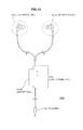
- FIG. 13 is a diagram showing an appearance of the NC earphone device 100 according to related art.
- the NC earphone device 100 shown in FIG. 13 is a so-called ear-hole insertion type of earphone device.
- the ear-hole insertion type of earphone device includes any earphone device of which sound output units are inserted into user's ear-holes so that the users may hear.
- the ear-hole insertion type of earphone device is an in-ear type of earphone device or a canal type of earphone device.
- the NC earphone device 100 shown in FIG. 13 is the canal type of NC earphone device.
- the NC device earphone 100 has a left channel (Lch) output unit 101 L, a right channel (Rch) output unit 101 R, a plug unit 102 , and a cord housing unit 103 .
- a cord connects the plug unit 102 to the cord housing unit 103 , and each cord connects the Lch output unit 101 L and the Rch output unit 101 R to the cord housing unit 103 , as illustrated in FIG. 13 .
- a driver unit outputting sounds corresponding to sound signals input from the plug unit 102 and a microphone recording external sounds for the realization of the noise cancelling function are installed in the Lch output unit 101 L and the Rch output unit 101 R, respectively.
- An electric circuit unit (a noise cancelling processing unit) to provide the noise cancelling function is installed inside of the cord housing unit 103 .
- the noise cancelling processing unit generates a noise cancelling signal of the left channel based on a Lch sound signal input from the plug unit 102 and a sound signal recorded from the microphone of the Lch output unit 101 L and a noise cancelling signal of the right channel based on a Rch sound signal input from the plug unit 102 and a sound signal recorded from the microphone of the Rch output unit 101 R.
- the noise cancelling processing unit drives the driver unit of the Lch output unit 101 L according to the noise cancelling signal of the left channel and the driver unit of the Rch output unit 101 R according to the noise cancelling signal of the right channel, users wearing the NC earphone device 100 may hear noise-cancelled sounds.
- the cord housing unit 103 has a battery case 103 A which accommodates a battery to supply electric power that are used to process the above mentioned noise cancelling.
- the NC earphone device 100 in related art has the cord housing unit 103 in which the electrical circuit for processing the noise cancelling and controlling various settings is formed.
- a micro-computer running the noise cancelling processing and the like has been implemented.
- the cord housing unit 103 has the battery case 103 A which accommodates the battery supplying electric power for the micro-computer.
- the size and weight of the code housing unit 103 becomes large in the NC earphone device 100 in related art.
- the cord housing unit 103 becomes heavy, the Lch output unit 101 L and the Rch output unit 101 R attached to users are easily pulled down so that the feeling of wearing may be impaired.
- the tension from the cord housing unit 103 due to the weight of the Lch and Rch output units 101 L and 101 R may be prevented such that the stability of the feeling of wearing may be improved.
- the clip is added to an earphone set and users are forced to effort to use the clip for the prevention of the tension.
- JP 2003-47083 is a related art describing that a battery is accommodated in a housing of an earphone.
- the Lch and Rch output units 101 L and 101 R are independently operated.
- the independent operation may cause sound differences between the Lch and Rch output units 101 L and 101 R such that users may feel the sense of incongruity.
- the sound reproduction device of this technology has a left channel housing accommodating at least one of a left channel driver unit outputting the left channel sound, a left channel microphone recording an external sound, or a left channel micro-computer controlling a setting for a noise-cancelling process based on the sound recorded by the left channel microphone.
- the sound reproduction device of this technology has a right channel housing accommodating at least one of a right channel driver unit outputting the right channel sound, a right channel microphone recording an external sound, or a right channel micro-computer controlling a setting for a noise-cancelling process based on the sound recorded by the right channel microphone.
- the left channel micro-computer and the right channel micro-computer are capable of data communication with each other.
- the left channel may easily check an operating status of the right channel. Accordingly, the technology has a two-channel operation which may achieve to prevent the incongruity of the left and right channels effectively due to no-checking the operating status of the other side of channel.
- each of the left channel housing unit and the right channel housing unit independently accommodates a micro-computer such that the technology includes the two-channel operation which may achieve to prevent the incongruity of the left and right channels effectively due to no-checking the operating status of the other side of channel. As a result, it may be prevented that users feel the sense of incongruity caused by operation differences between the left and right channels.
- FIG. 1 is an appearance diagram of the NC earphone device according to an embodiment
- FIG. 2 is an exploded perspective view of the Lch output unit according to an embodiment
- FIGS. 3A-C are drawings illustrating a position relationship of the microphone, the driver unit, and the battery accommodated in the housing;
- FIG. 4 is a block diagram illustrating internal components of the NC earphone device according to an embodiment
- FIGS. 5A-B are drawings illustrating a specific embodiment of the communication terminal
- FIG. 6 is a drawing illustrating a specific embodiment of the connection when users make various settings by using the communication terminal
- FIG. 7 is a drawing illustrating various functions of the left channel micro-computer and the right channel micro-computer;
- FIG. 8 is a flowchart illustrating a processing operation corresponding to NC mode synchronization control function unit
- FIG. 9 is a flowchart illustrating a processing operation corresponding to the error detection control unit
- FIG. 10 is a flowchart illustrating a processing operation corresponding to the simultaneous LR OFF control unit
- FIG. 11 is a flowchart illustrating a processing operation corresponding to the after-level-check simultaneous OFF control unit
- FIG. 12 is a flowchart illustrating a processing operation corresponding to the remaining level display control unit.
- FIG. 13 is an appearance diagram of the NC earphone device in related art.
- FIG. 1 is an appearance view of the noise cancelling (NC) earphone device according to an embodiment of the technology.
- the NC earphone device is referred an earphone device with a noise cancelling function. Because the NC earphone device performs to process the noise cancelling by itself, the user may enjoy a noise cancelling effect even when the NC earphone device is connected to a normal audio player.
- the NC earphone device 1 is so-called an ear-hole insertion type of earphone device.
- the ear-hole insertion type of earphone device includes any earphone device of which sound output units are inserted into user's ear-holes so that the users may hear.
- the ear-hole insertion type of earphone device is an in-ear type of earphone device or a canal type of earphone device.
- the NC earphone device 1 shown in FIG. 1 is the canal type of NC earphone device.
- the NC earphone device 1 includes a plug unit 2 , a left channel (Lch) output unit 3 L, a right channel (Rch) output unit 3 R, and a cord housing unit 4 .
- the NC earphone device 1 includes an input cord Ci connecting the plug unit 2 to the cord housing unit 4 , a left channel cord Cl connecting the Lch output unit 3 L to the cord housing unit 4 , and a right channel cord Cr connecting the Rch output unit 3 R to the cord housing unit 4 , as illustrated in FIG. 1 .
- the plug unit 2 is provided to enter sound signals output from an audio player which is connected to the NC earphone 1 .
- the plug unit 2 includes three terminals of a left channel (Lch), a right channel (Rch), and a ground (GND), and the input cord Ci includes three wires corresponding to each terminal of the Lch, the Rch, and the GND.
- the Lch output unit 3 L outputs sounds based on a left channel sound signal input from the plug unit 2
- the Rch output unit 3 R outputs sounds based on a right channel sound signal input from the plug unit 2
- the Lch output unit 3 L includes a housing 3 Lh as a case and an earpiece 3 Lp detachably mounted to the housing 3 Lh.
- the Rch output unit 3 R includes a housing 3 Rh as a case and an earpiece 3 Rp detachably mounted to the housing 3 Rh.
- the earpiece 3 Lp of the Lch output unit 3 L and the earpiece 3 Rp of the Rch output unit 3 R are inserted to a corresponding ear-hole, respectively, such that output sounds may be heard.
- the Lch output unit 3 L and the Rch output unit 3 R therefore, include microphones 11 l and 11 r recording the external sound, respectively.
- the cord housing unit 4 includes an operation unit enabling an on/off operation of the noise cancelling function, in other words a power on/off operation of the NC earphone device 1 .
- a control button 4 A is installed in the cord housing unit 4 , as illustrated in FIG. 1 , and users may perform the on/off operation of the NC earphone device 1 by the control button 4 A.
- the on/off operation may be achieved by pressing the control button 4 A. Pressing the control button 4 A in the off-state performs the on operation, and pressing the control button 4 A in the on-state performs the off operation.
- wires are branched to the left channel and the right channel in the cord housing unit 4 .
- the Lch, Rch, and GND wires of the input cord Ci are divided to a pair of Lch and GND and a pair of Rch and GND inside of the cord housing unit 4 , and the pair of Lch and GND reaches the Lch output unit 3 L through the Lch cord Cl and the pair of Rch and GND reaches the Rch output unit 3 R through the Rch cord Cr.
- the detailed wiring contained in the Lch cord Cl and the Rch cord Cr will be described later.
- FIGS. 2 and 3 describe a housing of the Lch output unit 3 L and the Rch output unit 3 R according to the embodiment.
- FIG. 2 shows an exploded perspective view of the Lch output unit 3 L.
- the Rch output unit 3 R is a left and right reverse form of the Lch output unit 3 L with an exception that an LED 15 is provided to the Rch output unit 3 R as illustrated in FIG. 4 .
- FIG. 2 both the Lch output unit 3 L and the Lch cord Cl are shown.
- the LED 15 as illustrated in FIG. 4 installed in the Rch output unit 3 R is an indicator which represents a remaining amount of the battery and an on/off state of the NC earphone device 1 .
- the Lch output unit 3 L includes a front housing piece 3 Lh-f and a rear housing piece 3 Rh-r which make up the housing 3 Lh shown in FIG. 1 , the earpiece 3 Lp shown in FIG. 1 , and a sleeve 20 guiding the Lch cord Cl in the housing 3 Lh.
- a microphone 11 l , a driver unit 12 l , a circuit board 21 , and a battery 13 l are accommodated inside of the housing 3 Lh having the front housing piece 3 Lh-f and the rear housing piece 3 Rh-r.
- the microphone 11 l is provided to record an external sound. Because a canal type of earphone device employs a feed forward (FF) method to cancel noises, a recording surface of the microphone 11 l is looking to an opposite direction to an output direction of the driver unit 12 l , in order to record the external sound outside of the housing 3 Lh.
- the microphone 11 l is a Micro Electro Mechanical Systems (MEMS) microphone.
- MEMS Micro Electro Mechanical Systems
- the circuit board 21 includes an electric circuit to achieve the noise cancelling function and other various functions described below.
- a left channel micro-computer 10 l or a right channel micro-computer 10 r of the Rch output unit 3 R is formed on the circuit board 21 .
- the battery 13 l is provided as part of operating a power source of the electrical circuit formed on the circuit board 21 .
- a button-shaped secondary battery may be used.
- the driver unit 12 l outputs or plays sounds based on sound signals.
- the driver unit 12 l may be a type of Balanced Armature (BA).
- BA Balanced Armature
- a hole of the earpiece 3 Lp fits a top tube, having an entrance of the sound emission, of the front housing piece 3 Lh-f such that the earpiece 3 LP is attached to the housing 3 Lh.
- FIG. 3 represents a positional relationship between the microphone 11 l , the driver unit 12 l , and the battery 13 l which are accommodated in the housing 3 Lh.
- FIGS. 3A , 3 B, and 3 C are perspective drawings of the Lch output unit 3 L, and a perspective view, a front view, and a top view, respectively.
- the housing 3 Lh is designed to have an approximately cylindrical space separated from a space in which the driver unit 12 l is accommodated.
- the approximately cylindrical space is designed to accommodate the circuit board 21 and the button-shaped battery 13 l .
- the battery 13 l and other components are effectively accommodated in the housing 3 Lh of the ear-hole insertion type of earphone device requesting that a housing of the sound output unit has a small size.
- the microphone 11 l may be a MEMS microphone. Because the MEMS microphone is small, the microphone as well as the battery 13 l and other components are easily accommodated in the housing 3 Lh, thereby improving the efficiency of the design, or increasing the degree of freedom in design.
- the driver unit 12 l is a BA type of the driver unit, and the BA type of the driver unit has a smaller size, compared to other types of the driver unit such as a dynamic type, such that the housing 3 Lh accommodating the battery 13 l and other components may be easily designed, thereby increasing the degree of freedom in design.
- the NC earphone device 1 since batteries 13 are accommodated in the housings 3 Lh and 3 Rh of the Lch output unit and the Rch output unit, the NC earphone device 1 is not used to have the battery box 103 A of the cord housing unit 103 in the NC earphone device 100 in related art. Accordingly, the cord housing unit 4 in the present NC earphone device 1 may be significantly small and light so that the weight of the cord housing unit 4 may reduce the deterioration of the feeling of wearing of the Lch and Rch sound output units and the like.
- the NC earphone device 1 includes the Lch sound output unit and the Rch sound output unit which are symmetrical bilaterally except the LED 15 .
- the earphone device that the left and right weights of the earphone device are balanced well and the feeling of wearing is excellent may be made.
- the difference between acoustic properties based on whether the weight of the LED 15 is added or not is negligent.
- any one of the Lch and Rch sound output units is designed reversely when the other of the Lch and Rch sound output units is designed, thereby designing easily.
- the sizes of the Lch and Rch sound output units may be equal to each other.
- FIG. 4 is a block diagram illustrating internal components of the NC earphone device according to an embodiment. Terminals Lch, Rch, and GND formed in the plug unit 2 are omitted in FIG. 4 .
- a left channel (Lch) signal and a right channel (Rch) signal input via the plug unit 2 is input inside of the housings 3 Lh and 3 Rh through the cord housing unit 4 .
- the Lch signal is supplied to the left channel microcomputer 10 l and a charging unit 14 l .
- two kinds of signals which are a signal through a capacitor Ccl and a signal not through the capacitor Ccl are input the Lch micro-computer 10 l as the Lch signal.
- the Rch signal is supplied to the right channel microcomputer 10 r and a charging unit 14 r .
- two kinds of signals which are a signal through a capacitor Ccr and a signal not through the capacitor Ccr are input the Rch micro-computer 10 r as the Rch signal.
- the capacitor Ccl and Ccr are provided for the cut of the DC component.
- the Lch signal through the capacitor Ccl and the Rch signal through the capacitor Ccr may be used to process the noise cancelling by the microcomputers 10 l and 10 r , respectively, or to process to drive the driver units 12 l and 12 r , respectively, when the noise cancelling function is turned off.
- signals not through the capacitors Ccl and Ccr which are signals without cutting the DC component, are input to the micro-computers 10 l and 10 r , respectively, because it is assumed that batteries 13 l and 13 r are charged through Lch and Rch wirings.
- a direct current is supplied through the Lch and Rch wirings, and the micro-computers 10 l and 10 r monitor the signals not through the capacitors Ccl and Ccr and determine whether the direct current is supplied or not.
- the micro-computers 10 l and 10 r instruct the charging units 14 l and 14 r to charge the batteries 13 l and 13 r , respectively.
- the charging control unit Fn 4 will be described later.
- the charging unit 14 l supplies the direct current through the Lch wiring connected to the charging unit 14 l to the battery 13 l and charges the battery 13 l .
- the charging unit 14 r supplies the direct current through the Rch wiring connected to the charging unit 14 r to the battery 13 r and charges the battery 13 r.
- the micro-computers 10 l and 10 r executes processes by various units Fn, as illustrated in FIG. 7 , which will be described later.
- the noise cancelling function is performed by the noise cancelling processing unit Fn 1 which will be described later.
- the Lch micro-computer 10 l generates a noise cancelling signal to cancel external sounds or noises based on the Lch signal input from the capacitor Ccl and a recording signal from the microphone 11 l , and drives the driver unit 12 l based on the noise cancelling signal. Accordingly, a user wearing the NC earphone device 1 may listen to an Lch sound that the external sounds are cancelled. In other words, a noise cancelling effect is obtained.
- a noise cancelling processing by the Rch micro-computer 10 r is described in the same way as the Lch micro-computer 10 l except the sign of L or R, so that detailed descriptions are omitted.
- the LED 15 is disposed in the housing 3 Rh, so that the Rch micro-computer 10 r controls to drive the emission of the LED 15 .
- the indicator display control unit Fn 6 will be described later.
- the Lch micro-computer 10 l and the Rch micro-computer 10 r are configured to communicate data with each other.
- the Lch micro-computer 10 l and the Rch micro-computer 10 r are configured to communicate data with each other by a wired connection.
- a serial communication method by Inter-Integrated Circuit (I2C) is employed, and the Lch micro-computer 10 l and the Rch micro-computer 10 r are connected to each other by wirings of data DATA, a clock CLK, and a ground GND.
- the wirings of data DATA, the clock CLK, and the ground GND connect the Lch micro-computer 10 l to the Rch micro-computer 10 r through the cord housing unit 4 .
- the Lch cord Cl and the Rch cord Cr described above include the wirings of data DATA, the clock CLK, and the ground GND.
- the wiring of the ground is shared with a ground wiring of sound signals.
- the cord housing unit 4 includes the control button 4 A and a switch SW.
- the switch SW is configured to inform the micro-computers 10 l and 10 r of whether the control button 4 A is pressed or not.
- an on/off control line ON/OFF extended from the switch SW is connected to the micro-computers 10 l and 10 r , and the switch SW is configured to disconnect the on/off control line to the wiring of the ground GND based on whether the control button 4 A is pressed or not.
- the on/off control line is connected to the Lch micro-computer 10 l and the Rch micro-computer 10 r through the Lch cord Cl and the Rch cord Cr, respectively.
- NC earphone devices are usually configured to adjust setting values for the noise cancelling processing based on an acoustic inspection, in order to absorb differences between NC earphone devices due to a predetermined timing such as a shipment timing of manufacturing.
- the NC earphone device 1 includes a communication terminal to allow setting values to be input from the outside of the NC earphone device 1 in the cord housing unit 4 .
- FIG. 5 is a drawing illustrating a specific embodiment of the communication terminal.
- communication terminals T is exposed on an opposite surface to a surface of the cord housing unit 4 in which the control button 4 A is formed.
- an opening 4 B is formed in the opposite surface of the cord housing unit 4 , and the communication terminals T is exposed within the opening 4 B.
- a data terminal Td, a clock terminal Tc, and a ground terminal Tg as the communication terminals T are formed according to the I2C method as the data communication system of the micro-computers 10 l and 10 r described above.
- the data terminal Td, the clock terminal Tc, and the ground terminal Tg are connected to the data line DATA, the clock line CLK, and the ground line GND, respectively.
- the opening 4 B is covered with an ornament 4 C before the NC earphone device 1 is shipped.
- the communication terminals T are not exposed to the outside when end users purchase the NC earphone device 1 .
- the micro-computers 10 l and 10 r for the noise cancelling processing are accommodated in the housings of the output unit 3 L and 3 R, respectively, and the communication terminals T to communicate data between the micro-computers 10 l and 10 r are disposed in the cord housing unit 4 .
- the acoustic inspection is processed under the same condition as actual using when the communication terminals T are exposed in the acoustic inspection, because any part of the output units 3 L and 3 R is not dissembled.
- the setting value for the noise cancelling processing may be adjusted appropriately.
- the settings for the micro-computers 10 l and 10 r using the communication terminals T may be adjusted by users as well as at a factory.
- a cradle 30 which is exclusively or generally accessible to predetermined information processing devices such as a personal computer 31 may be used.
- the cradle 30 includes a fitting portion to fit the cord housing unit 4 , and terminals to be connected to the data terminal Td, the clock terminal Tc, and the ground terminal Tg, respectively, are formed in the fitting portion when the cord housing unit 4 is fitted.
- Users may operate the personal computer 31 connected to the cradle 30 , so that users adjust various settings of the NC earphone device 1 , for example the micro-computers 10 l and 10 r , where the cord housing unit 4 is fitted to the cradle 30 .
- a firmware updates for the micro-computers 10 l and 10 r or a setting of the frequency characteristic of the equalizer may be also adjusted.
- FIG. 7 shows a block diagram for each function, the each function achieved by software processing of the Lch micro-computer 10 l and the Rch micro-computer 10 r .
- hardware such as function units Fn configured to process the various functions is described below.
- the Lch micro-computer 10 l includes a noise cancelling processing unit Fn 1 , an NC mode determination processing unit Fn 2 , a battery level detection unit Fn 3 , a charging control unit Fn 4 , and an external input setting processing unit Fn 5 .
- an NC mode synchronization control unit Fn 7 and an after-level-check simultaneous ON control unit Fn 10 are described later.
- the noise cancelling processing unit Fn 1 is described as illustrated in FIG. 4 .
- the noise cancelling processing unit Fn 1 generates the noise cancelling signal based on the recording signal from the microphone 11 l and the Lch signal input from the plug unit 2 , and drives the driver unit 12 l based on the noise cancelling signal.
- NC mode determination processing unit Fn 2 determines an appropriate NC mode depending on a condition of external noises.
- NC modes as NC filter characteristics may be predetermined as A mode (airplane), B mode (bus or train), or C mode (office) such that the NC mode determination processing unit Fn 2 determines an appropriate mode among the NC modes according the condition of external noises based on the recording signal from the microphone 11 l.
- the battery level detection unit Fn 3 detects a remaining amount of the battery 13 l .
- the charging control unit Fn 4 controls a charging operation of the charging unit 4 for the battery 13 l based on a determination result of whether the direct current for charging by the Lch wiring is supplied or not.
- the external input setting processing unit Fn 5 receives an input of settings from the external device connected to the communication terminals T and processes settings corresponding to the input. For example, when a filter coefficient of the NC filter is input as a setting value from the external device connected to the communication terminals T, a processing of setting the filter coefficient is executed
- the Rch micro-computer 10 r includes four function units Fn among the noise cancelling processing unit Fn 1 to the external input setting processing unit Fn 5 of the Lch micro-computer 10 l excluding the NC mode determination processing unit Fn 2 .
- the same reference numerals of the each function unit Fn with respect to the Lch micro-computer 10 l and the Rch micro-computer 10 r are represented, the function units Fn of the Rch micro-computer 10 r are described in the same way as the Lch micro-computer 10 l except the sign of L or R, so that detailed descriptions are omitted.
- the Rch micro-computer 10 r includes an indicator display control unit Fn 6 regarding the LED 15 in the housing 3 Rh, as well as the four function units Fn 1 , Fn 2 , Fn 3 , and Fn 4 .
- the indicator display control function unit Fn 6 verifies that the Rch micro-computer 10 r has a control function of driving the emission of the LED 15 .
- the NC mode synchronization control unit Fn 7 , the error detection control unit Fn 8 , the simultaneous LR OFF control unit Fn 9 , and the after-level-check simultaneous ON control unit Fn 10 in the Lch micro-computer 10 l are described below.
- the Lch micro-computer 10 l of the Lch and Rch micro-computers 10 l and 10 r acts as a master computer.
- the NC mode synchronization control unit Fn 7 executes a process for synchronizing on the NC mode of the Lch and Rch output units 3 L and 3 R.
- the same NC mode determined by the NC mode determination processing unit Fn 2 are set in both the Lch and Rch output units 3 L and 3 R.
- the NC mode synchronization control unit Fn 7 controls that switching timings of the NC modes are synchronized with the output units 3 L and 3 R in order to switch the NC modes simultaneously.
- the error detection control unit Fn 8 detects errors of the Rch micro-computer 10 r and performs a process corresponding to the errors. For example, in the embodiment, when a state that an operation of the Rch micro-computer 10 r has stopped due to any errors, in order words an OFF state of the NC processing, is detected, the Lch micro-computer 10 l is shut down or is turned off. In the embodiment, the determination of whether the Rch micro-computer 10 r has been stopped or not is performed sequentially when communicating regularly with the Rch micro-computer 10 l.
- the simultaneous LR OFF control unit Fn 9 is configured to turn off both channels simultaneously when a remaining battery level of any one channel of the both channels is insufficient or less than a predetermined level, even if there is a sufficient remaining amount of the other channel. Accordingly, this configuration may avoid discomfort of users better than a configuration that the left and right of the NC earphone device 1 operate incoherently.
- the after-level-check simultaneous ON control unit Fn 10 checks remaining battery levels of the batteries of the left and right channels in response to a power-on instruction from users by the control button 4 A, and controls to operate the left and right channels simultaneously only when remaining battery levels of the both channels are sufficient or more than a predetermined level.
- any one channel when an operation is attempted in case that a remaining battery level of any one channel is insufficient, any one channel may be operated but the other channel may be not operated. Accordingly, discomfort of users may occur due to differences in hearing between the left and right channels. However, the discomfort of users may be avoided effectively when operations of both channels are attempted in case that the remaining battery levels of both channels are sufficient.
- the Rch micro-computer 10 r includes the remaining level display control unit Fn 11 .
- the Rch micro-computer 10 r acts as a master computer.
- the remaining level display control unit Fn 11 is configured to display a remaining battery level of any one channel having a smaller remaining battery level than the other channel by the LED 15 .
- only one light emitting part of the LED 15 may be provided, so that the LED 15 may display the smaller remaining battery level as well as the ON/OFF state.
- these displays by the LED 15 may be configured based on a sequential timing. For example, the LED 15 may acts as an indicator for the display of the remaining battery level when the power is turned on, and then may acts as an indicator for the display of the ON/OFF state.
- the remaining level display control unit Fn 11 is performed by the Rch micro-computer 10 r , and checks the remaining battery levels of the right and left channels so that a light emission state of the LED 15 is controlled to display the smaller remaining battery level.
- an example of the display technique of the remaining battery level may be the emission brightness, a blink rate, or the like. After the remaining battery level is displayed, it is controlled that the light emission state of the LED 15 displays the ON state
- the both channels are compulsively turned off by the simultaneous LR OFF control unit Fn 9 when a remaining battery level of any one channel is insufficient even if a remaining battery level of the other channel is sufficient.
- an appropriate remaining battery level is informed users of the remaining level display control unit Fn 11 .
- the LED 15 is used to display the remaining battery level when the power is turned on, so that the display of the ON/OFF state and the display of the remaining battery level are performed by one light emission part, or share the one light emission part.
- FIG. 8 is a flowchart illustrating a processing operation corresponding to the NC mode synchronization control unit.
- step S 101 of “Lch” it is checked whether the NC mode is changed or not. In other words, it is waited until a new NC mode is determined by the NC mode determination processing unit Fn 2 .
- step S 101 When the NC mode is changed in step S 101 , the Rch is notified of the NC mode in step S 102 . In other words, the Rch is notified of the newly determined NC mode.
- the Rch replies to the Lch in Step S 201 .
- the reply is for the confirmation of the notification.
- the Lch is waiting for a reply from the Rch in step S 103 .
- step S 103 when there is a reply from the Rch, an instruction on switching a mode is executed to the Rch in step S 104 .
- the NC mode is switched in step S 105 .
- the NC mode is a newly determined NC mode, for example a filter characteristic of the NC filter.
- step S 202 the Rch is executed to switch to the notified NC mode based on the instruction on switching a mode in step S 104 . In other words, switching to the NC mode notified from step S 104 is executed.
- the Lch waits for a reply from the Rch in response to the notification of the NC mode, and the Lch switches the NC mode of its own, so that the timing of switching the NC mode is synchronized.
- the synchronization of the NC modes in the left and right channels is performed in the timing of switching the NC mode, but also the Lch as a master notifies the Rch of the current NC mode on a regular basis so that the synchronization of the NC modes is performed.
- FIG. 9 is a flowchart illustrating a processing operation corresponding to the error detection control unit. As illustrated in FIG. 9 , the Lch waits until there is a timing of the periodic communication in step S 301 . In other words, the Lch waits until the timing of the periodic communication with the Rch.
- a periodic notification is executed to the Rch in step S 302 .
- the Rch replies to the Lch in step S 401 .
- the Lch is determined whether there is the reply according to step S 401 or not.
- step S 303 when there is the reply, the process returns to step S 301 .
- the process returns to step S 301 when there is a reply thereby executing the loop process waiting until an operation stop state or an error state of the Rch is detected.
- step S 303 a negative result is obtained when there is no reply from the Rch, shutting down is performed in step S 304 .
- the Lch may be configured to be an off-state when the Rch is the operation stop state.
- FIG. 10 is a flowchart illustrating a processing operation corresponding to the simultaneous LR OFF control unit Fn 9 .
- the Lch waits until there is a timing of checking a remaining level in step S 501 .
- the timing of checking a remaining level refers a predetermined timing of checking a remaining battery level.
- the timing may be a predetermined period of time.
- a request to notify the Rch of a remaining level is performed in step S 502 .
- the Rch is configured to notify the Lch of the remaining level of the battery 13 r in step S 601 .
- the Lch is waiting for the notification of the remaining level according to step S 601 . Then, when there is the notification of the remaining level, it is determined whether remaining levels of the both batteries are sufficient or not in step S 504 . In other words, it is determined whether the remaining level of the battery 13 l detected by the battery level detection unit Fn 3 and the remaining level of the battery 13 r notified from the Rch both are sufficient or more than a predetermined level or not.
- step S 504 When the remaining levels of the both batteries 13 l and 13 r are sufficient to obtain a positive result in step S 504 , the process returns to step S 501 .
- the process returns to step S 501 when the positive result is obtained in step S 504 , thereby executing the loop process waiting until a negative result is obtained in step S 504 or the remaining levels of the both batteries 13 l and 13 r are insufficient.
- step S 505 is processed to instruct on OFF or shutting down to the Rch. Then, the off state is performed in step S 506 .
- the Rch is the off state in step S 602 .
- both the Lch and the Rch is moved to the off-state at the same time.
- FIG. 11 is a flowchart illustrating a processing operation corresponding to the after-level-check simultaneous OFF control unit
- FIG. 12 is a flowchart illustrating a processing operation corresponding to the remaining level display control unit.
- the processing according to the remaining level display control unit Fn 11 is performed in response to turning on of the power.
- the processing according to FIG. 12 is a consecutive process of the processing of FIG. 11 .
- the Lch waits until there is an ON operation in step S 701 .
- the Lch waits until a press of the control button 4 A is detected.
- a remaining level of the battery 13 l is detected as a remaining level detection processing of step S 702 , and then, the Lch is configured to request the notification of the remaining level to the Rch in step S 703 .
- the Rch performs to detect a remaining level of the battery 13 r as the remaining level detection processing of step S 801 according to the request for the remaining level notification of step S 703 , and after that, the Rch notifies the remaining level detected in step S 802 .
- the Lch starts to count time in step S 704 after requesting the notification of the remaining level in step S 703 .
- the time count is performed to count the elapsed time since making the request in step S 703 .
- step S 704 After starting the time count in step S 704 , the Lch waits until a condition of receiving the remaining level notification in step S 705 or timing out in step S 706 is satisfied. In other words, whether there is the remaining level notification or not is determined in step S 705 , and then, when a negative result is obtained due to no remaining level notification of the Rch, step S 706 is going to determine whether time is out or not, or whether a time count value in step S 704 reaches a predetermined value or not. Then, when a negative result is obtained due to no time-out in Step S 706 , the Lch goes back to step S 705 .
- step S 706 when a positive result with a time-out is obtained in step S 706 , it may be supposed that the Rch is on any error state, for example, a state that the Rch is incapable of replying due to the depletion of the remaining level of battery 13 r .
- step S 707 goes to reset the time count, and then, the processing is finished. Accordingly, the Lch may not be solely operated when the Rch is supposed to be incapable of operating, so that operating states of the left and light are balanced.
- step S 708 goes to determine whether remaining levels of both channels are sufficient.
- step S 709 goes to notify the Rch of the end notification, and then, the processing is finished.
- the Rch finishes the processing according to the end notification from the Lch in step S 709 , as shown in FIGS. 11 and 12 .
- step S 701 goes to perform the ON instruction or a start instruction, and then, the processing of switching to the ON state or starting is executed.
- the Rch executes the processing of switching to the ON state in step S 803 based on the ON instruction of step S 710 .
- both channels are operated simultaneously only when remaining levels of both channels are sufficient.
- the Rch starts by step S 803 , and then, the Rch requests the notification of the remaining level to the Lch in step S 804 .
- the Lch is configured to notify the Rch of the remaining level according to the request for the notification of the remaining level from the Rch in step S 712 .
- step S 805 the Rch waits for the notification of the remaining level from the Lch according to step S 712 .
- step S 806 the remaining levels of both channels are compared to each other in step S 806 , and then, the processing of displaying the smaller remaining level of both channels is executed in step S 807 .
- a light emitting operation of the LED 15 is controlled to obtain a light emission state representing the smaller remaining level of the batteries 13 l and 13 r.
- the Lch may receives the remaining level from the Rch so that the Lch may select the smaller remaining level of both channel to transfer the result of the selection to the Rch, thereby controlling to display the remaining level.
- the batteries 13 l and 13 r to achieve the noise cancelling function are accommodated in the housings of the Lch and the Rch, so that the battery case 103 A disposed in the cord housing unit 103 of the NC earphone device 100 in related art may not be used in the embodiment. Accordingly, the cord housing unit 4 is made significantly small and light, so that it may be prevented that the feeling of wearing of the Lch and Rch output units 3 L and 3 R is impaired by the weight of the cord housing unit 4 .
- the NC earphone device of the embodiment since the Lch and Rch output units 3 L and 3 R are symmetrical bilaterally, the NC earphone device that weights of the left and right are balanced well and the feeling of wearing is excellent may be achieved.
- Lch and Rch output units 3 L and 3 R are symmetrical bilaterally, empty spaces in the housings of the Lch and the Rch are the same as each other, so that acoustic characteristics of the Lch and the Rch are the same as each other, thereby achieving the natural feeling of hearing.
- both the batteries 13 l and 13 r may be disposed in only one housing of both output units, but by this configuration, the housings of the Lch and the Rch are designed separately.
- the Lch and Rch output units 3 L and 3 R are symmetrical bilaterally, the ease of design may significantly increase because one output unit may be designed by reversing the design of the other output unit regarding the design of the Lch and Rch output units 3 L and 3 R.
- the circuit boards 21 or the micro-computers 10 are accommodated in the Lch and Rch output units 3 L and 3 R, respectively. Accordingly, the circuit boards 21 executing the noise cancelling processing are accommodated in the same housing as the microphones 11 , so that a wiring distance between the microphones 11 and the circuit boards 21 may be significantly shorter than the configuration that a circuit board is disposed in the cord housing unit 103 as the earphone device in related art. As a result, the noise generated in the sound recording signal of the microphones 11 may be reduced. In addition, radiation arising from the wiring between the circuit boards 21 and the microphones 11 may be reduced.
- the power supply wiring to the cord housing unit from the battery accommodated in the output unit for the power supply to the circuit board is extended, and as such extent, the number of the wiring increases and a diameter of the cord also increases.
- the described above may be avoided effectively by accommodating the circuit boards 21 in the output units 3 L and 3 R according to the NC earphone device 1 .
- the micro-computers 10 for the noise cancelling processing are accommodated in the housings of the output units 3 L and 3 R, respectively, and terminals T for the data communication between the micro-computers 10 are disposed in the cord housing unit 4 .
- the acoustic inspection is processed under the same condition as actual using when the communication terminals T are exposed in the acoustic inspection, because any part of the output units 3 L and 3 R is not dissembled.
- the setting value for the noise cancelling processing may be adjusted appropriately.
- the Lch micro-computer 10 l and the Rch micro-computer 10 r are configured to communicate data from each other, so that one channel may check an operation status of the other channel. Accordingly, it may be avoided effectively that the discomfort for the incongruity of the left and right channel operation occurs because the Lch and the Rch fail to check the operation status of each other, and therefore, operations of both channels are balanced. As a result, it may be avoided effectively that users feel the discomfort for the incongruity of the left and right channel operation.
- the batteries 13 are accommodated in the Lch and Rch output units 3 L and 3 R, but the batteries 13 may be accommodated in the cord housing unit in the technology.
- the technology is applied not only to the earphone device, but also suitably to headphone devices such as an overhead type headphone.
- the technology is applied not only to FF method as a noise cancelling method, but also to FB method suitably.
- the FB method may be suitably applied to the overhead type headphone device.
- the microphones 11 may be installed in a position that may record sounds generated in a space between a user's ear and the microphone 11 . The sounds may be both of the external noise sound leaking into the user's ear and the sound output from the driver unit.
- present technology may also be configured as below.
- a sound reproduction device comprising:
- a left channel housing unit that accommodates at least a left channel driver unit outputting a left channel sound, a left channel microphone recording an external sound, and a left channel micro-computer controlling a setting for a noise cancelling processing based on a recording signal of the left channel microphone;
- a right channel housing unit that accommodates at least a right channel driver unit outputting a right channel sound, a right channel microphone recording an external sound, and a right channel micro-computer controlling a setting for a noise cancelling processing based on a recording signal of the right channel microphone
- left channel micro-computer and the right channel micro-computer are configured to communicate data with each other.
- one of the left channel micro-computer and the right channel micro-computer is a master computer, and wherein the master computer is configured to detect whether remaining levels of the left channel battery and the right channel battery are sufficient, and the master computer is configured to perform control so that the left channel micro-computer and the right channel micro-computer are in an OFF state when at least one of the remaining levels of the left channel battery and the right channel battery is insufficient.
Landscapes
- Engineering & Computer Science (AREA)
- Physics & Mathematics (AREA)
- Acoustics & Sound (AREA)
- Signal Processing (AREA)
- Manufacturing & Machinery (AREA)
- Soundproofing, Sound Blocking, And Sound Damping (AREA)
- Headphones And Earphones (AREA)
- Fittings On The Vehicle Exterior For Carrying Loads, And Devices For Holding Or Mounting Articles (AREA)
Priority Applications (1)
| Application Number | Priority Date | Filing Date | Title |
|---|---|---|---|
| US14/608,810 US9578410B2 (en) | 2011-08-31 | 2015-01-29 | Sound reproduction device |
Applications Claiming Priority (2)
| Application Number | Priority Date | Filing Date | Title |
|---|---|---|---|
| JP2011189552A JP5919686B2 (ja) | 2011-08-31 | 2011-08-31 | 音響再生装置 |
| JP2011-189552 | 2011-08-31 |
Related Child Applications (1)
| Application Number | Title | Priority Date | Filing Date |
|---|---|---|---|
| US14/608,810 Continuation US9578410B2 (en) | 2011-08-31 | 2015-01-29 | Sound reproduction device |
Publications (2)
| Publication Number | Publication Date |
|---|---|
| US20130051561A1 US20130051561A1 (en) | 2013-02-28 |
| US8976987B2 true US8976987B2 (en) | 2015-03-10 |
Family
ID=46982362
Family Applications (2)
| Application Number | Title | Priority Date | Filing Date |
|---|---|---|---|
| US13/562,041 Expired - Fee Related US8976987B2 (en) | 2011-08-31 | 2012-07-30 | Sound reproduction device |
| US14/608,810 Expired - Fee Related US9578410B2 (en) | 2011-08-31 | 2015-01-29 | Sound reproduction device |
Family Applications After (1)
| Application Number | Title | Priority Date | Filing Date |
|---|---|---|---|
| US14/608,810 Expired - Fee Related US9578410B2 (en) | 2011-08-31 | 2015-01-29 | Sound reproduction device |
Country Status (5)
| Country | Link |
|---|---|
| US (2) | US8976987B2 (enExample) |
| EP (1) | EP2566185A3 (enExample) |
| JP (1) | JP5919686B2 (enExample) |
| CN (1) | CN102970636B (enExample) |
| TW (1) | TWI530198B (enExample) |
Cited By (5)
| Publication number | Priority date | Publication date | Assignee | Title |
|---|---|---|---|---|
| US20160066078A1 (en) * | 2014-08-28 | 2016-03-03 | Samsung Electronics Co., Ltd. | Wearable electronic device |
| US9451350B2 (en) | 2011-08-31 | 2016-09-20 | Sony Corporation | Earphone device |
| US9578410B2 (en) | 2011-08-31 | 2017-02-21 | Sony Corporation | Sound reproduction device |
| US9706284B2 (en) | 2015-05-26 | 2017-07-11 | Fender Musical Instruments Corporation | Intelligent headphone |
| CN109584644A (zh) * | 2019-01-21 | 2019-04-05 | 温州大学瓯江学院 | 一种学校语音室用辅助装置 |
Families Citing this family (6)
| Publication number | Priority date | Publication date | Assignee | Title |
|---|---|---|---|---|
| US9681213B2 (en) * | 2015-05-04 | 2017-06-13 | Sony Corporation | Headphone device, audio device, and method for operating a headphone device |
| CN109863757B (zh) * | 2016-10-21 | 2020-12-04 | 伯斯有限公司 | 用于助听的设备和系统 |
| EP3603108A4 (en) * | 2017-03-30 | 2021-04-14 | Magic Leap, Inc. | TWO-WAY NON-BLOCKING HEADPHONES |
| CN114286218B (zh) | 2020-09-28 | 2024-10-01 | 南宁富联富桂精密工业有限公司 | 无线耳机及提升无线耳机续航力的方法 |
| US12041424B2 (en) * | 2021-03-11 | 2024-07-16 | Google Llc | Real-time adaptation of audio playback |
| JP7678556B2 (ja) * | 2021-04-23 | 2025-05-16 | パナソニックIpマネジメント株式会社 | 音響装置および音響制御方法 |
Citations (18)
| Publication number | Priority date | Publication date | Assignee | Title |
|---|---|---|---|---|
| US20020131613A1 (en) * | 2001-03-13 | 2002-09-19 | Andreas Jakob | Method for establishing a binaural communication link and binaural hearing devices |
| US20030014566A1 (en) | 1997-01-13 | 2003-01-16 | Micro Ear Technology, Inc., D/B/A Micro-Tech | System for programming hearing aids |
| JP2003047083A (ja) | 2001-08-02 | 2003-02-14 | Hosiden Corp | 電池内蔵型ヘッドセット |
| US6839447B2 (en) * | 2000-07-14 | 2005-01-04 | Gn Resound A/S | Synchronized binaural hearing system |
| EP1558059A2 (en) | 2005-04-18 | 2005-07-27 | Phonak Ag | Controlling a gain setting in a hearing instrument |
| EP1608202A2 (en) | 2004-06-15 | 2005-12-21 | Bose Corporation | Noise reduction headset |
| US7039195B1 (en) * | 2000-09-01 | 2006-05-02 | Nacre As | Ear terminal |
| US7215766B2 (en) * | 2002-07-22 | 2007-05-08 | Lightspeed Aviation, Inc. | Headset with auxiliary input jack(s) for cell phone and/or other devices |
| US20080159568A1 (en) * | 2006-12-27 | 2008-07-03 | Sony Corporation | Sound outputting apparatus, sound outputting method, sound output processing program and sound outputting system |
| US20080253583A1 (en) * | 2007-04-09 | 2008-10-16 | Personics Holdings Inc. | Always on headwear recording system |
| US20100166207A1 (en) | 2008-12-26 | 2010-07-01 | Sony Corporation | Headphone apparatus and reproducing apparatus |
| WO2010140087A1 (en) | 2009-06-02 | 2010-12-09 | Koninklijke Philips Electronics N.V. | Earphone arrangement and method of operation therefor |
| US20110038496A1 (en) * | 2009-08-17 | 2011-02-17 | Spear Labs, Llc | Hearing enhancement system and components thereof |
| US8050439B2 (en) * | 2009-05-25 | 2011-11-01 | Panasonic Corporation | Hearing aid system |
| US20120033824A1 (en) * | 2009-01-28 | 2012-02-09 | Creative Technology Ltd | Earphone set |
| US20120087510A1 (en) * | 2010-10-08 | 2012-04-12 | Gerrit Johannes Willem Sampimon | Noise Cancelling Stereo Headset |
| US8295497B2 (en) * | 2006-07-12 | 2012-10-23 | Phonak Ag | Method for operating a binaural hearing system as well as a binaural hearing system |
| US8498428B2 (en) * | 2010-08-26 | 2013-07-30 | Plantronics, Inc. | Fully integrated small stereo headset having in-ear ear buds and wireless connectability to audio source |
Family Cites Families (39)
| Publication number | Priority date | Publication date | Assignee | Title |
|---|---|---|---|---|
| US5448646A (en) | 1993-11-01 | 1995-09-05 | Unex Corporation | Headset interface assembly |
| JP3513935B2 (ja) | 1994-09-08 | 2004-03-31 | ソニー株式会社 | 通信端末 |
| FR2749453B1 (fr) | 1996-05-31 | 1998-09-04 | Sgs Thomson Microelectronics | Filtre audio analogique pour frequences aigues |
| US6321278B1 (en) | 1998-09-14 | 2001-11-20 | Compaq Computer Corporation | Automatically detecting a connection into a computer system standardized connector for disabling a front speaker |
| JP2000261534A (ja) | 1999-03-10 | 2000-09-22 | Nippon Telegr & Teleph Corp <Ntt> | 送受話器 |
| NO312570B1 (no) | 2000-09-01 | 2002-05-27 | Sintef | Stöybeskyttelse med verifiseringsanordning |
| JP2002112383A (ja) * | 2000-10-02 | 2002-04-12 | Toshiba Corp | 音楽再生装置及びオーディオプレーヤとヘッドフォン |
| JP2003264883A (ja) | 2002-03-08 | 2003-09-19 | Denso Corp | 音声処理装置および音声処理方法 |
| FR2861916A1 (fr) | 2003-10-31 | 2005-05-06 | St Microelectronics Sa | Commande d'un transistor mos en element de redressement |
| US7349550B2 (en) | 2004-01-07 | 2008-03-25 | Hearing Components, Inc. | Earbud adapter |
| JP4352932B2 (ja) | 2004-02-26 | 2009-10-28 | ソニー株式会社 | マイクロホン装置 |
| JP4458269B2 (ja) * | 2005-05-18 | 2010-04-28 | 株式会社オーディオテクニカ | ノイズキャンセルヘッドフォン |
| US20070177741A1 (en) | 2006-01-31 | 2007-08-02 | Williamson Matthew R | Batteryless noise canceling headphones, audio device and methods for use therewith |
| GB2479674B (en) | 2006-04-01 | 2011-11-30 | Wolfson Microelectronics Plc | Ambient noise-reduction control system |
| US20070230734A1 (en) | 2006-04-04 | 2007-10-04 | Knowles Electronics, Llc | Monitor Transducer System and Manufacturing Method Thereof |
| DE112007001275T5 (de) | 2006-05-30 | 2009-04-23 | Knowles Electronics, LLC, Itasca | Personenhöreinrichtung |
| US8335320B2 (en) | 2006-10-03 | 2012-12-18 | Sony Corporation | Audio apparatus |
| US20080166006A1 (en) | 2007-01-06 | 2008-07-10 | Apple Inc | Light diffuser |
| JP2008197438A (ja) | 2007-02-14 | 2008-08-28 | Sony Corp | 信号処理装置、信号処理方法 |
| US8385560B2 (en) | 2007-09-24 | 2013-02-26 | Jason Solbeck | In-ear digital electronic noise cancelling and communication device |
| US20100226505A1 (en) | 2007-10-10 | 2010-09-09 | Tominori Kimura | Noise canceling headphone |
| US20090147982A1 (en) | 2007-12-06 | 2009-06-11 | Rohm Co., Ltd. | Headphone set and headphone cable |
| JP2009141698A (ja) | 2007-12-06 | 2009-06-25 | Rohm Co Ltd | ヘッドセット |
| JP5353044B2 (ja) * | 2008-04-15 | 2013-11-27 | ソニー株式会社 | 信号処理装置、信号処理方法 |
| JP2010147982A (ja) | 2008-12-22 | 2010-07-01 | Hosiden Corp | リモコン付きステレオイヤホンマイク |
| JP4760903B2 (ja) | 2008-12-26 | 2011-08-31 | ソニー株式会社 | 情報処理装置及び情報処理方法 |
| JP5298951B2 (ja) * | 2009-02-27 | 2013-09-25 | ヤマハ株式会社 | 補聴器 |
| US8254592B2 (en) | 2009-04-10 | 2012-08-28 | Apple Inc. | Electronic device and external equipment with configurable audio path circuitry |
| UA105805C2 (uk) | 2009-09-10 | 2014-06-25 | Косс Корпорейшн | Синхронізація бездротових навушників |
| US8532318B2 (en) * | 2009-10-13 | 2013-09-10 | Panasonic Corporation | Hearing aid device |
| EP2505000A2 (en) | 2009-11-23 | 2012-10-03 | Incus Laboratories Limited | Production of ambient noise-cancelling earphones |
| JP5123969B2 (ja) | 2010-03-12 | 2013-01-23 | 株式会社リヒトラブ | 綴じ具 |
| JP5671929B2 (ja) | 2010-10-12 | 2015-02-18 | ソニー株式会社 | イヤホン、音響変換装置 |
| JP5817113B2 (ja) | 2010-12-24 | 2015-11-18 | ソニー株式会社 | 音声信号出力装置、音声出力システム、音声信号出力方法 |
| JP5760867B2 (ja) | 2011-08-31 | 2015-08-12 | ソニー株式会社 | 音響再生装置 |
| JP5919686B2 (ja) | 2011-08-31 | 2016-05-18 | ソニー株式会社 | 音響再生装置 |
| JP6019553B2 (ja) | 2011-08-31 | 2016-11-02 | ソニー株式会社 | イヤホン装置 |
| JP6069829B2 (ja) | 2011-12-08 | 2017-02-01 | ソニー株式会社 | 耳孔装着型収音装置、信号処理装置、収音方法 |
| JP6069830B2 (ja) | 2011-12-08 | 2017-02-01 | ソニー株式会社 | 耳孔装着型収音装置、信号処理装置、収音方法 |
-
2011
- 2011-08-31 JP JP2011189552A patent/JP5919686B2/ja not_active Expired - Fee Related
-
2012
- 2012-07-20 EP EP12177259.4A patent/EP2566185A3/en not_active Ceased
- 2012-07-30 US US13/562,041 patent/US8976987B2/en not_active Expired - Fee Related
- 2012-08-20 TW TW101130115A patent/TWI530198B/zh not_active IP Right Cessation
- 2012-08-24 CN CN201210308136.XA patent/CN102970636B/zh not_active Expired - Fee Related
-
2015
- 2015-01-29 US US14/608,810 patent/US9578410B2/en not_active Expired - Fee Related
Patent Citations (18)
| Publication number | Priority date | Publication date | Assignee | Title |
|---|---|---|---|---|
| US20030014566A1 (en) | 1997-01-13 | 2003-01-16 | Micro Ear Technology, Inc., D/B/A Micro-Tech | System for programming hearing aids |
| US6839447B2 (en) * | 2000-07-14 | 2005-01-04 | Gn Resound A/S | Synchronized binaural hearing system |
| US7039195B1 (en) * | 2000-09-01 | 2006-05-02 | Nacre As | Ear terminal |
| US20020131613A1 (en) * | 2001-03-13 | 2002-09-19 | Andreas Jakob | Method for establishing a binaural communication link and binaural hearing devices |
| JP2003047083A (ja) | 2001-08-02 | 2003-02-14 | Hosiden Corp | 電池内蔵型ヘッドセット |
| US7215766B2 (en) * | 2002-07-22 | 2007-05-08 | Lightspeed Aviation, Inc. | Headset with auxiliary input jack(s) for cell phone and/or other devices |
| EP1608202A2 (en) | 2004-06-15 | 2005-12-21 | Bose Corporation | Noise reduction headset |
| EP1558059A2 (en) | 2005-04-18 | 2005-07-27 | Phonak Ag | Controlling a gain setting in a hearing instrument |
| US8295497B2 (en) * | 2006-07-12 | 2012-10-23 | Phonak Ag | Method for operating a binaural hearing system as well as a binaural hearing system |
| US20080159568A1 (en) * | 2006-12-27 | 2008-07-03 | Sony Corporation | Sound outputting apparatus, sound outputting method, sound output processing program and sound outputting system |
| US20080253583A1 (en) * | 2007-04-09 | 2008-10-16 | Personics Holdings Inc. | Always on headwear recording system |
| US20100166207A1 (en) | 2008-12-26 | 2010-07-01 | Sony Corporation | Headphone apparatus and reproducing apparatus |
| US20120033824A1 (en) * | 2009-01-28 | 2012-02-09 | Creative Technology Ltd | Earphone set |
| US8050439B2 (en) * | 2009-05-25 | 2011-11-01 | Panasonic Corporation | Hearing aid system |
| WO2010140087A1 (en) | 2009-06-02 | 2010-12-09 | Koninklijke Philips Electronics N.V. | Earphone arrangement and method of operation therefor |
| US20110038496A1 (en) * | 2009-08-17 | 2011-02-17 | Spear Labs, Llc | Hearing enhancement system and components thereof |
| US8498428B2 (en) * | 2010-08-26 | 2013-07-30 | Plantronics, Inc. | Fully integrated small stereo headset having in-ear ear buds and wireless connectability to audio source |
| US20120087510A1 (en) * | 2010-10-08 | 2012-04-12 | Gerrit Johannes Willem Sampimon | Noise Cancelling Stereo Headset |
Cited By (10)
| Publication number | Priority date | Publication date | Assignee | Title |
|---|---|---|---|---|
| US9451350B2 (en) | 2011-08-31 | 2016-09-20 | Sony Corporation | Earphone device |
| US9578410B2 (en) | 2011-08-31 | 2017-02-21 | Sony Corporation | Sound reproduction device |
| US10212504B2 (en) | 2011-08-31 | 2019-02-19 | Sony Corporation | Earphone device |
| US9992567B2 (en) | 2014-05-23 | 2018-06-05 | Federal Musical Instruments Corporation | Intelligent headphone |
| US20160066078A1 (en) * | 2014-08-28 | 2016-03-03 | Samsung Electronics Co., Ltd. | Wearable electronic device |
| US9615161B2 (en) * | 2014-08-28 | 2017-04-04 | Samsung Electronics Co., Ltd. | Wearable electronic device |
| US9955248B2 (en) | 2014-08-28 | 2018-04-24 | Samsung Electronics Co., Ltd. | Wearable electronic device |
| US9706284B2 (en) | 2015-05-26 | 2017-07-11 | Fender Musical Instruments Corporation | Intelligent headphone |
| CN109584644A (zh) * | 2019-01-21 | 2019-04-05 | 温州大学瓯江学院 | 一种学校语音室用辅助装置 |
| CN109584644B (zh) * | 2019-01-21 | 2020-11-24 | 温州大学瓯江学院 | 一种学校语音室用辅助装置 |
Also Published As
| Publication number | Publication date |
|---|---|
| US9578410B2 (en) | 2017-02-21 |
| EP2566185A2 (en) | 2013-03-06 |
| TWI530198B (zh) | 2016-04-11 |
| CN102970636B (zh) | 2019-03-29 |
| JP2013051624A (ja) | 2013-03-14 |
| TW201328370A (zh) | 2013-07-01 |
| JP5919686B2 (ja) | 2016-05-18 |
| CN102970636A (zh) | 2013-03-13 |
| US20150222979A1 (en) | 2015-08-06 |
| EP2566185A3 (en) | 2013-12-25 |
| US20130051561A1 (en) | 2013-02-28 |
Similar Documents
| Publication | Publication Date | Title |
|---|---|---|
| US10212504B2 (en) | Earphone device | |
| US8976987B2 (en) | Sound reproduction device | |
| SE542485C2 (en) | Charging and storage of wireless earbuds | |
| US9832560B1 (en) | Headset providing private and detachable loudspeaker audio and external device charging | |
| TWM550006U (zh) | 無線耳機組 | |
| US20220116696A1 (en) | Wireless playback device, and playback control methodand apparatus thereof | |
| US20190327551A1 (en) | Wireless headphone system | |
| JP2020057929A (ja) | 複数電源対応ワイヤレスイヤホン及び当該ワイヤレスイヤホンの制御方法 | |
| JP5760867B2 (ja) | 音響再生装置 | |
| WO2023020322A1 (zh) | 无线耳机、耳机盒及无线耳机系统 | |
| CN208863048U (zh) | 一种无线播放设备及头戴式无线耳机系统 | |
| US10171903B2 (en) | Portable binaural recording, processing and playback device | |
| JP6304336B2 (ja) | イヤホン装置 | |
| US20250126393A1 (en) | Headphone with touchscreen | |
| EP3352474B1 (en) | Microphone receiver and microphone receiver system | |
| KR101561782B1 (ko) | 분리형 도킹 스피커 | |
| WO2022251401A1 (en) | Removeable speaker for computing devices | |
| TW201431387A (zh) | 具擴充功能之耳機 |
Legal Events
| Date | Code | Title | Description |
|---|---|---|---|
| AS | Assignment |
Owner name: SONY CORPORATION, JAPAN Free format text: ASSIGNMENT OF ASSIGNORS INTEREST;ASSIGNORS:OZAWA, NORIYUKI;NISHIDA, OSAMU;TSUNODA, NAOTAKA;REEL/FRAME:028862/0390 Effective date: 20120719 |
|
| FEPP | Fee payment procedure |
Free format text: PAYOR NUMBER ASSIGNED (ORIGINAL EVENT CODE: ASPN); ENTITY STATUS OF PATENT OWNER: LARGE ENTITY |
|
| STCF | Information on status: patent grant |
Free format text: PATENTED CASE |
|
| MAFP | Maintenance fee payment |
Free format text: PAYMENT OF MAINTENANCE FEE, 4TH YEAR, LARGE ENTITY (ORIGINAL EVENT CODE: M1551); ENTITY STATUS OF PATENT OWNER: LARGE ENTITY Year of fee payment: 4 |
|
| FEPP | Fee payment procedure |
Free format text: MAINTENANCE FEE REMINDER MAILED (ORIGINAL EVENT CODE: REM.); ENTITY STATUS OF PATENT OWNER: LARGE ENTITY |
|
| LAPS | Lapse for failure to pay maintenance fees |
Free format text: PATENT EXPIRED FOR FAILURE TO PAY MAINTENANCE FEES (ORIGINAL EVENT CODE: EXP.); ENTITY STATUS OF PATENT OWNER: LARGE ENTITY |
|
| STCH | Information on status: patent discontinuation |
Free format text: PATENT EXPIRED DUE TO NONPAYMENT OF MAINTENANCE FEES UNDER 37 CFR 1.362 |
|
| FP | Lapsed due to failure to pay maintenance fee |
Effective date: 20230310 |