US8912722B2 - Sub headlight unit and sub headlight system for use in vehicle that leans into turns, and vehicle that leans into turns - Google Patents
Sub headlight unit and sub headlight system for use in vehicle that leans into turns, and vehicle that leans into turns Download PDFInfo
- Publication number
- US8912722B2 US8912722B2 US13/772,607 US201313772607A US8912722B2 US 8912722 B2 US8912722 B2 US 8912722B2 US 201313772607 A US201313772607 A US 201313772607A US 8912722 B2 US8912722 B2 US 8912722B2
- Authority
- US
- United States
- Prior art keywords
- sub headlight
- vehicle
- headlight light
- light source
- light sources
- Prior art date
- Legal status (The legal status is an assumption and is not a legal conclusion. Google has not performed a legal analysis and makes no representation as to the accuracy of the status listed.)
- Expired - Fee Related, expires
Links
Images


Classifications
-
- B—PERFORMING OPERATIONS; TRANSPORTING
- B60—VEHICLES IN GENERAL
- B60Q—ARRANGEMENT OF SIGNALLING OR LIGHTING DEVICES, THE MOUNTING OR SUPPORTING THEREOF OR CIRCUITS THEREFOR, FOR VEHICLES IN GENERAL
- B60Q1/00—Arrangement of optical signalling or lighting devices, the mounting or supporting thereof or circuits therefor
- B60Q1/02—Arrangement of optical signalling or lighting devices, the mounting or supporting thereof or circuits therefor the devices being primarily intended to illuminate the way ahead or to illuminate other areas of way or environments
- B60Q1/04—Arrangement of optical signalling or lighting devices, the mounting or supporting thereof or circuits therefor the devices being primarily intended to illuminate the way ahead or to illuminate other areas of way or environments the devices being headlights
- B60Q1/18—Arrangement of optical signalling or lighting devices, the mounting or supporting thereof or circuits therefor the devices being primarily intended to illuminate the way ahead or to illuminate other areas of way or environments the devices being headlights being additional front lights
-
- B—PERFORMING OPERATIONS; TRANSPORTING
- B60—VEHICLES IN GENERAL
- B60Q—ARRANGEMENT OF SIGNALLING OR LIGHTING DEVICES, THE MOUNTING OR SUPPORTING THEREOF OR CIRCUITS THEREFOR, FOR VEHICLES IN GENERAL
- B60Q1/00—Arrangement of optical signalling or lighting devices, the mounting or supporting thereof or circuits therefor
- B60Q1/0029—Spatial arrangement
- B60Q1/0041—Spatial arrangement of several lamps in relation to each other
-
- B—PERFORMING OPERATIONS; TRANSPORTING
- B60—VEHICLES IN GENERAL
- B60Q—ARRANGEMENT OF SIGNALLING OR LIGHTING DEVICES, THE MOUNTING OR SUPPORTING THEREOF OR CIRCUITS THEREFOR, FOR VEHICLES IN GENERAL
- B60Q1/00—Arrangement of optical signalling or lighting devices, the mounting or supporting thereof or circuits therefor
- B60Q1/02—Arrangement of optical signalling or lighting devices, the mounting or supporting thereof or circuits therefor the devices being primarily intended to illuminate the way ahead or to illuminate other areas of way or environments
- B60Q1/04—Arrangement of optical signalling or lighting devices, the mounting or supporting thereof or circuits therefor the devices being primarily intended to illuminate the way ahead or to illuminate other areas of way or environments the devices being headlights
- B60Q1/06—Arrangement of optical signalling or lighting devices, the mounting or supporting thereof or circuits therefor the devices being primarily intended to illuminate the way ahead or to illuminate other areas of way or environments the devices being headlights adjustable, e.g. remotely-controlled from inside vehicle
- B60Q1/08—Arrangement of optical signalling or lighting devices, the mounting or supporting thereof or circuits therefor the devices being primarily intended to illuminate the way ahead or to illuminate other areas of way or environments the devices being headlights adjustable, e.g. remotely-controlled from inside vehicle automatically
- B60Q1/12—Arrangement of optical signalling or lighting devices, the mounting or supporting thereof or circuits therefor the devices being primarily intended to illuminate the way ahead or to illuminate other areas of way or environments the devices being headlights adjustable, e.g. remotely-controlled from inside vehicle automatically due to steering position
-
- B—PERFORMING OPERATIONS; TRANSPORTING
- B62—LAND VEHICLES FOR TRAVELLING OTHERWISE THAN ON RAILS
- B62J—CYCLE SADDLES OR SEATS; AUXILIARY DEVICES OR ACCESSORIES SPECIALLY ADAPTED TO CYCLES AND NOT OTHERWISE PROVIDED FOR, e.g. ARTICLE CARRIERS OR CYCLE PROTECTORS
- B62J45/00—Electrical equipment arrangements specially adapted for use as accessories on cycles, not otherwise provided for
- B62J45/40—Sensor arrangements; Mounting thereof
- B62J45/41—Sensor arrangements; Mounting thereof characterised by the type of sensor
- B62J45/415—Inclination sensors
- B62J45/4151—Inclination sensors for sensing lateral inclination of the cycle
-
- B—PERFORMING OPERATIONS; TRANSPORTING
- B62—LAND VEHICLES FOR TRAVELLING OTHERWISE THAN ON RAILS
- B62J—CYCLE SADDLES OR SEATS; AUXILIARY DEVICES OR ACCESSORIES SPECIALLY ADAPTED TO CYCLES AND NOT OTHERWISE PROVIDED FOR, e.g. ARTICLE CARRIERS OR CYCLE PROTECTORS
- B62J6/00—Arrangement of optical signalling or lighting devices on cycles; Mounting or supporting thereof; Circuits therefor
- B62J6/02—Headlights
- B62J6/022—Headlights specially adapted for motorcycles or the like
- B62J6/023—Headlights specially adapted for motorcycles or the like responsive to the lean angle of the cycle, e.g. changing intensity or switching sub-lights when cornering
-
- B—PERFORMING OPERATIONS; TRANSPORTING
- B60—VEHICLES IN GENERAL
- B60Q—ARRANGEMENT OF SIGNALLING OR LIGHTING DEVICES, THE MOUNTING OR SUPPORTING THEREOF OR CIRCUITS THEREFOR, FOR VEHICLES IN GENERAL
- B60Q2300/00—Indexing codes for automatically adjustable headlamps or automatically dimmable headlamps
- B60Q2300/10—Indexing codes relating to particular vehicle conditions
- B60Q2300/13—Attitude of the vehicle body
- B60Q2300/136—Roll
-
- B62K2207/02—
Definitions
- the present invention relates to a sub headlight unit and a sub headlight system for use in a vehicle that leans into turns, and a vehicle that leans into turns.
- a rider In general, in a vehicle that leans into turns (such as saddle-ride type vehicles including motorcycles, three-wheeled motor vehicles, snowmobiles, and ATVs (all terrain vehicles), for example), when the vehicle corners or turns at an intersection, a rider operates a handlebar and additionally shifts his/her own weight in order to counteract centrifugal force acting on a vehicle body. As a result, the vehicle turns with an attitude (hereinafter, also referred to as “lean attitude”) leaning to the inner side of a curve.
- lean attitude attitude
- a rider operates a steering wheel and turns with centrifugal force acting on a vehicle body. Therefore, in the vehicle that does not lean into turns, the vehicle body leans to the outer side of a curve due to the centrifugal force.
- the turning is made with an active use of the weight shifting of the rider himself/herself. Therefore, the vehicle body largely leans.
- the vehicle body leans to the outer side of the curve due to the centrifugal force.
- the degree of this leaning varies depending on the running speed of the vehicle and the magnitude (radius) of the curve, and this leaning of the vehicle body is not utilized for the turning.
- it is preferable that the amount of leaning to the outer side of the curve due to the centrifugal force is small.
- a vehicle is provided with a plurality of lights irrespective of whether or not the vehicle leans into turns.
- the lights include a light intended mainly to ensure a field of view of a rider of the vehicle and a light intended mainly to allow a surrounding vehicle or the like to recognize the presence of the rider's own vehicle.
- a headlight is the light intended mainly to ensure the field of view of the rider of the vehicle, and in general, is configured to switch between a high beam (running headlight) and a low beam (passing headlight).
- an illumination range of a headlight light source spreads evenly to the left and right in an area ahead in an advancing direction and below a horizontal plane including the headlight light source.
- the vehicle that leans into turns is running on a road curving to the left, the vehicle runs with the vehicle body inclined to the left. Accordingly, the illumination range of the headlight light source spreads downward to the left. As a result, a nearer position on a running lane is illuminated. Thus, the illumination range in an area inside the curve and ahead in the advancing direction is reduced.
- a vehicle has been proposed in which, in addition to a main headlight that illuminates an area ahead of the vehicle, a pair of right and left sub headlights that are turned on depending on the magnitude of a lean angle (angle of inclination of a vehicle body to the inner side of a curve relative to an upright state thereof) are provided as the headlight (Japanese Patent No. 4806550).
- a situation under which the vehicle corners or turns at an intersection is not always the same.
- a rider's field of view at a time of turning a curve varies depending on the vehicle speed and also on the radius of a road, and the like.
- the lean angle is small in a curve with a large radius so that the illumination range is reduced to a small extent, while the lean angle is large in a curve with a small radius so that the illumination range is reduced to a large extent. Accordingly, for example, in a case of continuously moving through a plurality of curves having different radii during touring on a mountain road, the illumination range of the headlight changes in each curve even though the speed does not change so much. As a result, the field of view ahead in a path changes. When such a change in the field of view ahead in a path during a curve is small, a rider is more likely to feel safe.
- the pair of right and left sub headlights are turned on in accordance with the lean angle.
- a light emission direction of the sub headlight is lower than a horizontal plane.
- the mirror is rotated in accordance with the magnitude of the lean angle, and thereby the orientation of the optical axis can be continuously changed.
- the mirror is rotated in accordance with the magnitude of the lean angle, and thereby the orientation of the optical axis can be continuously changed.
- a change in the optical axis direction of the headlight itself is used to respond to a reduction in the illumination range of the headlight. This achieves a compact size of the headlight unit.
- the headlight of variable optical axis type disclosed in the BMW article has a compact size, and is quite useful.
- preferred embodiments of the present invention provide a vehicle that leans into turns and a sub headlight unit and a sub headlight system for use in a vehicle that leans into turns, by which illumination ranges suitable for a wide variety of running scenes are obtained while preventing an increase in size.
- the present inventors have conducted intensive studies of the problem that the conventional techniques have difficulties in sufficiently suppressing and preventing a change in the field of view ahead in a path caused by a difference in a situation of moving through a curve, and the present inventors have discovered the following.
- the orientation of the sub headlight is set such that, along with an increase in the lean angle of a vehicle, an illumination range of the sub headlight starts to cover a position that has been out of the illumination range.
- the orientation of the sub headlight is set based on the correspondence relationship between an increase in the lean angle and a reduction in the illumination range.
- a sub headlight unit for use in a vehicle that leans into turns includes a plurality of sub headlight light sources that illuminate, at one side with respect to a width direction of the vehicle, an area ahead and outward of the vehicle with respect to the width direction of the vehicle, wherein the brightness of the sub headlight light source changes in accordance with a lean angle of the vehicle, when the lean angle of the vehicle reaches a reference value that is individually set for each of the sub headlight light sources, the sub headlight light source exhibits a predetermined brightness, as the reference value set for the sub headlight light source is greater, an outer edge of an illumination range of the sub headlight light source having a predetermined illuminance is located farther outward with respect to the width direction of the vehicle in a plan view.
- the outer edge of the illumination range of the sub headlight light source having the predetermined illuminance preferably is located farther outward with respect to the width direction of the vehicle in a plan view. Accordingly, as the lean angle of the vehicle is larger, a farther outward position with respect to the width direction of the vehicle is illuminated.
- the lean angle of the vehicle increases when moving at a high speed, and even at the same speed, the lean angle of the vehicle increases when moving through a curve having a smaller radius.
- the rider seeks to see a position or area farther ahead in a path or a position farther into a curve.
- a farther outward position with respect to the width direction of the vehicle is illuminated. Therefore, such a change in the rider's line of sight can be responded to. This enables illumination to be performed with an illumination range suitable for each of a wide variety of running scenes.
- illumination with illumination ranges suitable for a wide variety of running scenes is achieved by using the plurality of sub headlight light sources. Therefore, any mechanism and any member that moves the optical axis of the sub headlight light source are not required. Accordingly, there is no necessity to increase the size of the sub headlight in order to outwardly widen a range that the sub headlight can illuminate, and it is relatively easy to outwardly widen the illumination range.
- an outer edge of an illumination range of the sub headlight light source having a predetermined illuminance obtained when the vehicle is in an upright state preferably is located farther outward with respect to the width direction of the vehicle.
- a larger angle preferably is formed in a plan view between an optical axis of the sub headlight light source and a center line of the vehicle in a front-back direction thereof.
- the sub headlight light source whose optical axis is directed farther outward is brightened. This enables illumination to be performed with an illumination range more suitable for each of a wide variety of running scenes.
- the center line of the vehicle in the front-back direction is a straight line that extends in the front-back direction of the vehicle while moving through the center of the vehicle with respect to the width direction of the vehicle on a horizontal plane located at the same level as a main headlight light source (low beam light source) of the vehicle. Accordingly, when the vehicle is shifted from the upright state into the leaning state, the center line is shifted laterally with respect to the width direction of the vehicle.
- the angle formed between the optical axis of the sub headlight light source and the center line is an angle formed therebetween, in a plan view, at a time when the sub headlight light source exhibits the predetermined brightness as a result of the sub headlight light source reaching the reference value.
- the plurality of sub headlight light sources preferably are located at the one side of the vehicle with respect to the width direction of the vehicle, as the reference value set for the sub headlight light source is greater, an outer edge of an illumination range having a predetermined illuminance generated at the one side by the sub headlight light source among the plurality of sub headlight light sources preferably is located farther outward with respect to the width direction of the vehicle.
- the illumination is provided by the plurality of sub headlight light sources that are provided at one side of the vehicle with respect to the width direction of the vehicle toward a direction ahead of and lateral to the vehicle at the one side. Therefore, the distance from the light source to an illumination target is shortened. This enables illumination to be more effectively performed with an illumination range suitable for each of a wide variety of running scenes.
- the sub headlight light sources provided at the left side of the vehicle with respect to the width direction of the vehicle illuminate an area ahead and at the left side of the vehicle. Therefore, all of a turning direction, the position of the light source that is turned on, and an illuminating direction are at the left side with respect to the width direction of the vehicle.
- the turning direction, the position of the light source that is turned on, and the illuminating direction are coincident with respect to the width direction of the vehicle, an uncomfortable feeling is not given to, for example, a rider of an oncoming vehicle.
- an illumination range of the sub headlight light source obtained when the vehicle is in an upright state preferably is located increasingly upwardly, as the illumination range of the sub headlight light source is located more upwardly, an outer edge of an illumination range having a predetermined illuminance generated by the sub headlight light source among the plurality of sub headlight light sources is located farther outward with respect to the width direction of the vehicle.
- the brightnesses of the plurality of sub headlight light sources are sequentially changed in accordance with an increase in the lean angle.
- the illumination range is widened upward and outward. This enables illumination to be performed with an illumination range suitable for each of a wide variety of running scenes, and at the same time enables illumination to be efficiently performed in accordance with an increase in the lean angle.
- An optical axis of the sub headlight light source is fixed, as the reference value set for the sub headlight light source is greater, an outer edge of an illumination range having a predetermined illuminance generated by the sub headlight light source among the plurality of sub headlight light sources whose optical axes are fixed is located farther outward with respect to the width direction of the vehicle.
- the optical axes of the plurality of sub headlight light sources are fixed. Therefore, any movable mechanism and any movable member that moves the optical axes of the sub headlight light sources are not provided. Accordingly, there is no necessity to increase the sizes of a movable mechanism and a movable member in order to outwardly widen a range that the illumination can reach. Thus, a size increase is prevented.
- a cut-off line of the sub headlight light source obtained when the vehicle in an upright state is seen from the front side of the vehicle, preferably is inclined at a larger inclination angle.
- the sub headlight light source When the lean angle of the vehicle reaches a reference value that is individually set for each of the sub headlight light sources, the sub headlight light source is turned on, as the reference value set for the sub headlight light source is greater, an outer edge of an illumination range having a predetermined illuminance generated by the sub headlight light source at a time when the sub headlight light source is turned on is located farther outward with respect to the width direction of the vehicle.
- the sub headlight upon reaching the reference value, the sub headlight is turned on so that the illumination range of the sub headlight covers an area where the rider's line of sight is directed. This enables illumination to be effectively performed with an illumination range suitable for each of a wide variety of running scenes.
- the sub headlight light source When the lean angle of the vehicle reaches a reference value that is individually set for each of the sub headlight light sources, the sub headlight light source is turned on in a full light state, as the reference value set for the sub headlight light source is greater, an outer edge of an illumination range having a predetermined illuminance generated by the sub headlight light source at a time when the sub headlight light source is turned on in the full light state is located farther outward with respect to the width direction of the vehicle.
- the sub headlight upon reaching the reference value, the sub headlight is turned on in the full light state so that the illumination range of the sub headlight covers and brightens an area where the rider's line of sight is directed. This enables illumination to be more effectively performed with an illumination range suitable for each of a wide variety of running scenes.
- the sub headlight units are preferably provided at the one side of the vehicle, when the vehicle is in an upright state, and the sub headlight light source having a greater reference value is preferably located at the outer side of the sub headlight light source having a smaller reference value with respect to the width direction of the vehicle.
- the rider When the vehicle moves through a curve, the rider is more likely to see a position farther into the curve (farther outward with respect to the width direction of the vehicle) in accordance with an increase in the lean angle of the vehicle.
- the sub headlight light source located farther outward is turned on. This makes it easy to ensure a wide illumination range in an area lateral to the vehicle such that a position that the rider desires to see is much more likely to be illuminated.
- the turn-on of the sub headlight light sources in accordance with an increase in the lean angle is performed preferably in the order from the inner sub headlight light source to the outer sub headlight light source, and the outer edges of the illumination ranges of the sub headlights are arranged from the inner side to the outer side as the lean angle increases.
- both the order of turn-on in accordance with an increase in the lean angle and the order of arrangement of the outer edges of the illumination ranges in accordance with an increase in the lean angle are from the inner side to the outer side.
- these orders are coincident with each other.
- the sub headlight light source having a greater reference value preferably is located higher than the sub headlight light source having a smaller reference value.
- the sub headlight light sources preferably are located such that the heights thereof are lowered in accordance with an increase in the lean angle. Accordingly, as for the extent of vertical movement of the sub headlight light source from when the vehicle is in the upright state to when the sub headlight light source reaches the reference value, the extent of movement of the sub headlight light source having a greater reference value is larger than the extent of movement of the sub headlight light source having a smaller reference value.
- the sub headlight light source having a greater reference value preferably is located lower than the sub headlight light source having a smaller reference value.
- the frequency of reaching the predetermined brightness is higher in the sub headlight light source having a smaller reference value than in the sub headlight light source having a greater reference value.
- the sub headlight light source having a smaller reference value is located at a relatively high position at a time when this sub headlight light source is turned on.
- a relatively wide illumination range is ensured as the illumination range of the sub headlight light source having a smaller reference value.
- the sub headlight light source is turned on at a relatively high position, it is easy to set an illumination range on the road surface. It is also easy for the rider to visually recognize an obstacle (such as unevenness on the road surface) and an area behind the obstacle. This enables the sub headlight light sources to achieve illumination more suitable for a wide variety of running scenes.
- the plurality of sub headlight light sources are preferably arranged near or adjacent to one another, and when the vehicle is in an upright state, the positions of the sub headlight light sources neighboring one another are partially coincident with respect to a height direction.
- a difference in the height among the sub headlight light sources at times when they are turned on is made further smaller. This can more effectively prevent the occurrence of a situation where the rider feels uncomfortable due to a change, which depends on a running scene, in the illumination range of the sub headlight light source within the rider's field of view at a time when the sub headlight light source is turned on. This enables the sub headlight light sources to achieve illumination that is more suitable for a wide variety of running scenes.
- the plurality of sub headlight light sources are preferably arranged in a horizontal direction.
- a difference in the height among the sub headlight light sources at times when they are turned on is made further smaller. This can more effectively prevent an occurrence of a situation where the rider feels uncomfortable due to a change, which depends on a running scene, in the illumination range of the sub headlight light source within the rider's field of view at a time when the sub headlight light source is turned on. This enables the sub headlight light sources to achieve illumination that is more suitable for a wide variety of running scenes.
- a front cover is preferably included in the vehicle and has a curved surface that is outwardly convex and extends from a front center portion with respect to the width direction of the vehicle in a direction rearward and outward with respect to the width direction of the vehicle.
- the plurality of sub headlight light sources are preferably arranged along the curved surface of the front cover.
- This configuration enables placement of the sub headlight light sources and setting of light distributions of the sub headlight light sources to be readily implemented. Thus, it is easy to ensure a relatively wide illumination range as the illumination range of each of the sub headlight light sources that emit light in different directions.
- the outermost sub headlight light source located preferably is located above a main headlight provided in the vehicle, the main headlight being configured to illuminate an area ahead in front of the vehicle.
- the sub headlight light source that is turned on when the lean angle is larger is located at a high position. Accordingly, illumination can be made from a high position. This can delay a timing of approaching of the cut-off line from the side of the vehicle in accordance with an increase in the lean angle after the sub headlight light source is turned on. Additionally, this can prevent or minimize a reduction in the illumination range, which occurs in accordance with an increase in the lean angle. Moreover, illumination from a high position enables setting of the illumination range to be readily implemented. Furthermore, illumination from a high position makes an obstacle (such as unevenness on the road surface) and an area behind the obstacle easily viewable to the rider.
- a sub headlight system for use in a vehicle that leans into turns includes the sub headlight unit according to any one of the preferred embodiments of the present invention described above; a controller that changes the brightnesses of the plurality of sub headlight light sources in accordance with the lean angle of the vehicle; and a detector that detects a variable available to obtain the lean angle of the vehicle, wherein, when the lean angle of the vehicle reaches a reference value that is individually set for each of the sub headlight light sources, the controller causes the corresponding sub headlight light source to exhibit a predetermined brightness.
- an AFS Adaptive Front-Lighting System
- a vehicle that leans into turns includes the sub headlight system described above.
- illumination with illumination ranges suitable for a wide variety of running scenes are achieved while preventing an increase in size.
- the optical axis is a straight line that moves through a light source and the center of a maximum illuminance portion of emitted light.
- the center of the maximum illuminance portion of the emitted light can be identified by emitting light from a light source to a screen that is placed ahead of the light source.
- This screen illuminance test can be implemented by a method specified in JIS D1619.
- the cut-off line and the illumination range having the predetermined illuminance can be identified based on a result (such as an isolux distribution map) of the screen illuminance test mentioned above.
- the cut-off line and the illumination range having the predetermined illuminance in a plan view can be identified based on a road-surface light distribution that is obtained by converting the result of the screen illuminance test mentioned above into the road-surface light distribution.
- the conversion into the road-surface light distribution can be implemented by a conventionally known method.
- conversion from a screen illuminance value into a road-surface illuminance value can be performed.
- the following expression (I) is usable.
- D represents a light source
- E represents a point on a road surface
- F represents a point of intersection at which the screen placed between D and E intersects with a straight line connecting D to E.
- Road-surface illuminance( Lx ) Screen Illuminance( Lx ) ⁇ [(Distance between D and F ( m ))/(Distance between D and E ( m ))] 2 (I)
- illumination with illumination ranges suitable for a wide variety of running scenes are achieved without any size increase.
- FIG. 1 is a front elevational view schematically showing a motorcycle according to a preferred embodiment of the present invention.
- FIG. 2 is a block diagram showing a basic configuration concerning sub headlight light sources of the motorcycle shown in FIG. 1 .
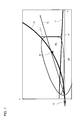
- FIG. 3 is a front elevational view schematically showing optical axes and cut-off lines of the sub headlight light sources of the motorcycle in an upright state.
- FIG. 4 is a plan view schematically showing an illumination range of a headlight having an illuminance L 1 in a case where a vehicle moves through a curve having a radius R 1 at a speed V 1 .
- FIG. 5 is a plan view schematically showing an illumination range of a headlight having the illuminance L 1 in a case where a vehicle moves through a curve having the radius R 1 at a speed V 2 .
- FIG. 6 is a plan view schematically showing an illumination range of a headlight having the illuminance L 1 in a case where a vehicle moves through a curve having the radius R 1 at a speed V 3 .
- FIG. 7 is a plan view schematically showing an illumination range of a headlight having the illuminance L 1 in a case where a vehicle moves through a curve having a radius R 4 at a speed V 4 .
- FIG. 8 is a plan view schematically showing an illumination range of a headlight having the illuminance L 1 in a case where a vehicle moves through a curve having a radius R 3 at the speed V 4 .
- FIG. 9 is a plan view schematically showing an illumination range of a headlight having the illuminance L 1 in a case where a vehicle moves through a curve having a radius R 2 at the speed V 4 .
- FIG. 10 is a plan view for the comparison among the illumination ranges having the illuminance L 1 shown in FIGS. 4 to 6 .
- FIG. 11 is a plan view for the comparison among illumination ranges having an illuminance L 2 (L 2 >L 1 ) under the same circumstances as in FIG. 10 .
- FIG. 12 is a front elevational view schematically showing, on an enlarged scale, a portion of a motorcycle according to another preferred embodiment of the present invention.
- FIG. 13 is a left side view showing, on an enlarged scale, a portion of the motorcycle shown in FIG. 12 .
- FIGS. 14A and 14B are front elevational views each schematically showing, on an enlarged scale, a portion of a motorcycle according to another preferred embodiment of the present invention.
- FIG. 15 is a perspective view schematically showing a sub headlight unit provided in the motorcycles shown in FIGS. 14A and 14B .
- FIGS. 16A to 16D are front elevational views each schematically showing, on an enlarged scale, a portion of a motorcycle according to another preferred embodiment of the present invention.
- FIGS. 17A to 17F are front elevational views each schematically showing, on an enlarged scale, a portion of a motorcycle according to another preferred embodiment of the present invention.
- FIG. 1 is a front elevational view schematically showing a motorcycle according to a preferred embodiment of the present invention.
- a motorcycle 10 is a non-limiting example of a vehicle that leans into turns according to a preferred embodiment of the present invention.
- vehicle that leans into turns For example, saddle-ride type vehicles including motorcycles, three-wheeled motor vehicles, snowmobiles, and ATVs (all terrain vehicles) may be provided as a preferred embodiment of the present invention.
- front and back are terms with respect to an advancing direction of the vehicle
- up” and “down” are terms with respect to the vertical direction of the vehicle
- the terms “right” and “left” are terms with respect to a rider.
- the motorcycle 10 includes a handlebar 12 .
- An operation switch 15 is provided in a left portion of the handlebar 12 with respect to a width direction of the vehicle.
- the operation switch 15 includes a beam switch 15 B and a flasher switch 15 F (see FIG. 2 ).
- a steering shaft (not shown) is fixed to a center portion of the handlebar 12 with respect to the width direction of the vehicle.
- the steering shaft extends downward through a headpipe (not shown).
- a frontfork 17 is provided at a lower end of the steering shaft.
- a front wheel 16 is rotatably supported at the lower end of the frontfork 17 .
- the headpipe is a member constituting a vehicle body frame. In the present invention, no particular limitation is put on the vehicle body frame, and a conventional known configuration is adoptable.
- a front cover 18 covers a front portion of the headpipe having the steering shaft moving therethrough.
- a main headlight 11 is provided in a center portion with respect to the width direction of the vehicle.
- the main headlight 11 includes a high beam light source 11 H (running headlight) and a low beam light source 11 L (passing headlight).
- the high beam light source 11 H illuminates an area ahead of the motorcycle 10 at a height equal to or above a horizontal plane of the main headlight 11 .
- the low beam light source 11 L illuminates an area ahead of the motorcycle 10 at a height below the horizontal plane of the main headlight 11 .
- the high beam light source 11 H and the low beam light source 11 L are configured such that only one of them preferably is turned on at one time, for example.
- the rider operates the beam switch 15 B (see FIG. 2 ) to switch turn-on of the high beam light source 11 H and turn-on of the low beam light source 11 L.
- the motorcycle 10 includes a sub headlight 13 .
- the sub headlight 13 includes two sub headlight units 13 L and 13 R of variable light distribution type. Each of the sub headlight units 13 L and 13 R is provided at each side with respect to the width direction of the vehicle.
- the sub headlight unit 13 L includes a plurality of sub headlight light sources 13 La, 13 Lb, and 13 Lc.
- the sub headlight light sources 13 La, 13 Lb, and 13 Lc are arranged in this order from the center toward the upper left with respect to the width direction of the vehicle. Illumination ranges of the sub headlight light sources 13 La, 13 Lb, and 13 Lc are arranged in this order from the center toward the upper left with respect to the width direction of the vehicle.
- the illumination ranges of the sub headlight light sources 13 La, 13 Lb, and 13 Lc overlap one another.
- the sub headlight unit 13 R includes a plurality of sub headlight light sources 13 Ra, 13 Rb, and 13 Rc.
- the sub headlight light sources 13 Ra, 13 Rb, and 13 Rc are arranged in this order from the center toward the upper right with respect to the width direction of the vehicle.
- Illumination ranges of the sub headlight light sources 13 Ra, 13 Rb, and 13 Rc are arranged in this order from the center toward the upper right with respect to the width direction of the vehicle.
- the illumination ranges of the sub headlight light sources 13 Ra, 13 Rb, and 13 Rc overlap one another.
- the sub headlight unit 13 L is arranged at the left side of the motorcycle 10 with respect to the width direction of the vehicle.
- the plurality of sub headlight light sources 13 La to 13 Lc included in the sub headlight unit 13 L illuminate the side (left side) where the sub headlight unit 13 L is arranged with respect to the width direction of the vehicle.
- Different reference values are set for the sub headlight light sources 13 La to 13 Lc, as will be described later.
- the sub headlight light source for which this reference value is set is turned on.
- the reference value increases in the order of the reference value set for the sub headlight light source 13 La, the reference value set for the sub headlight light source 13 Lb, and the reference value set for the sub headlight light source 13 Lc.
- the sub headlight light sources 13 La, 13 Lb, and 13 Lc are arranged in this order from the inside to the outside (left side) with respect to the width direction of the vehicle. That is, the sub headlight light source having a greater reference value is located farther outward (left side) with respect to the width direction of the vehicle than the sub headlight light source having a smaller reference value.
- the sub headlight light sources 13 La, 13 Lb, and 13 Lc are arranged in this order from the lower side to the upper side. That is, the sub headlight light source having a greater reference value is located higher than the sub headlight light source having a smaller reference value.
- the front cover 18 includes a curved surface that is outwardly convex and extends from a front center portion with respect to the width direction of the vehicle in a direction rearward and outward with respect to the width direction of the vehicle.
- the plurality of sub headlight light sources 13 La to 13 Lc are arranged along the curved surface of the front cover 18 . That is, an optical axis of the sub headlight light source located outward with respect to the width direction of the vehicle is oriented more outward with respect to the width direction of the vehicle than an optical axis of the sub headlight light source located inward with respect to the width direction of the vehicle.
- the sub headlight light source 13 Lc that is located outermost when the motorcycle 10 is in the upright state is positioned above the main headlight 11 (the high beam light source 11 H and the low beam light source 11 L).
- the sub headlight unit 13 R preferably is identical to the sub headlight unit 13 L. Therefore, a description thereof will be omitted.
- the optical axes of the sub headlight light sources 13 La to 13 Lc and 13 Ra to 13 Rc are fixed, and not moved in accordance with the lean angle.
- a reflector (not shown) of the sub headlight light source is also fixed, and not moved in accordance with the lean angle.
- no particular limitation is put on the sub headlight light source.
- an LED is adoptable as the sub headlight light source.
- a mono-focus type light source is also adoptable as the sub headlight light source.
- the above-described arrangement manner is merely an illustrative example of a preferred embodiment of the present invention. The present invention is not limited to this example.
- Flashers 14 L and 14 R serving as direction indicators, are provided at both sides of the motorcycle 10 with respect to the width direction of the vehicle.
- the flashers 14 L and 14 R are configured such that only one of them preferably flashes at one time, except for when a hazard light mode is activated.
- the rider operates the flasher switch 15 F (see FIG. 2 ), and thereby flashing/turn-off of the flashers 14 L and 14 R is switched.
- the plurality of sub headlight light sources 13 La, 13 Lb, and 13 Lc which are positioned at the left side in the motorcycle 10 with respect to the width direction of the vehicle, are arranged between the main headlight 11 and the flasher 14 L.
- the plurality of sub headlight light sources 13 Ra, 13 Rb, and 13 Rc which are positioned at the right side in the motorcycle 10 , are arranged between the main headlight 11 and the flasher 14 R.
- no particular limitation is put on the positional relationship between the sub headlight light source and the flasher with respect to the width direction of the vehicle.
- the sub headlight light source is provided outside the flasher with respect to the width direction of the vehicle.
- the plurality of sub headlight light sources 13 La, 13 Lb, and 13 Lc are preferably provided above the main headlight 11 and the flasher 14 L.
- the plurality of sub headlight light sources 13 Ra, 13 Rb, and 13 Rc are preferably provided above the main headlight 11 and the flasher 14 R.
- the plurality of sub headlight light sources 13 La to 13 Lc which are provided to the left with respect to the width direction of the vehicle, illuminate an area ahead and at the left side of the motorcycle 10 .
- the plurality of sub headlight light sources 13 Ra to 13 Rc which are provided to the right with respect to the width direction of the vehicle, illuminate an area ahead and at the right side of the motorcycle 10 .
- FIG. 2 is a block diagram showing a basic configuration concerning the sub headlight light sources of the motorcycle shown in FIG. 1 .
- the operation switch 15 includes the beam switch 15 B and the flasher switch 15 F.
- the beam switch 15 B is connected to the high beam light source 11 H and the low beam light source 11 L included in the main headlight 11 .
- the rider operates the beam switch 15 B, turn-on/turn-off of the high beam light source 11 H and the low beam light source 11 L is switched in accordance with the operation performed on the beam switch 15 B.
- the flasher switch 15 F is connected to the flashers 14 L and 14 R.
- the rider operates the flasher switch 15 F, one of the flashers 14 L and 14 R is caused to flash in accordance with the operation performed on the flasher switch 15 F.
- an attitude detection sensor 22 and a vehicle speed sensor 23 are preferably provided.
- the attitude detection sensor 22 preferably is a gyro sensor that detects the angular velocity about an axis in the front-back direction of the motorcycle 10 .
- the attitude detection sensor 22 supplies, to a controller 20 , a signal indicating the detected angular velocity (roll rate) about the axis in the front-back direction.
- the vehicle speed sensor 23 detects the vehicle speed, and supplies, to the controller 20 , a signal indicating the detected vehicle speed. Each time a predetermined timing comes during running, the controller 20 calculates the lean angle of the motorcycle 10 based on the angular velocity about the axis in the front-back direction and the vehicle speed.
- the roll rate is integrated over time, and the vehicle speed is used as correction information so as to calculate the lean angle.
- a method for calculating the lean angle is not limited to this example.
- the vehicle speed is not an essential variable.
- a conventionally known method is adoptable.
- the calculation may be performed based on a static equilibrium equation by using the yaw rate (angular velocity about an axis in the vertical direction) and the vehicle speed.
- the correction information is not limited to the vehicle speed. For example, it may be acceptable to provide a plurality of gyro sensors and G sensors and use values obtained from these sensors and the vehicle speed as the correction information.
- GPS position information and/or geomagnetic information may be used as the correction information.
- sensors detectiontors
- An appropriate sensor may be provided in accordance with variables available for the calculation.
- the controller 20 preferably includes a memory (not shown).
- the memory stores, in the form of data, a plurality of reference values (°) to be compared with the lean angle.
- the memory preferably stores three reference values (a first reference value K 1 , a second reference value K 2 , and a third reference value K 3 ).
- the first reference value K 1 , the second reference value K 2 , and the third reference value K 3 satisfy the relationship of first reference value K 1 ⁇ second reference value K 2 ⁇ third reference value K 3 .
- the first reference value K 1 is associated with the sub headlight light sources 13 La and 13 Ra.
- the second reference value K 2 is associated with the sub headlight light sources 13 Lb and 13 Rb.
- the third reference value K 3 is associated with the sub headlight light sources 13 Lc and 13 Rc.
- the first to third reference values K 1 to K 3 are greater than 0°, and different from one another.
- the first to third reference values K 1 to K 3 are set to be values sequentially increasing at intervals from 0°.
- the interval between 0° and K 1 is K 1 .
- the intervals K 1 , K 2 ′, and K 3 ′ satisfy K 1 >K 2 ′>K 3 ′.
- a greater reference value (K 1 to K 3 ) has a smaller interval (K 1 , K 2 ′, K 3 ′).
- the relationship between the reference value and the interval is not limited to this example.
- the sub headlight light source 13 La is turned on, and when the lean angle reaches the second reference value K 2 , the sub headlight light source 13 Lb is turned on, and when the lean angle reaches the third reference value K 3 , the sub headlight light source 13 Lc is turned on.
- the sub headlight light sources 13 La, 13 Lb, and 13 Lc are sequentially turned on along with an increase in the lean angle.
- the sub headlight light sources 13 Lc, 13 Lb, and 13 La are sequentially turned off. The same applies to a case where the motorcycle 10 is inclined to the right.
- the sub headlight light source when the lean angle is less than a minimum reference value (K 1 ) (for example, at a time of running straight ahead), the sub headlight light source may be dimmed.
- K 1 a minimum reference value
- the sub headlight light sources 13 La, 13 Lb, and 13 Lc are sequentially turned on along with an increase in the lean angle
- the sub headlight light sources 13 Rc, 13 Rb, and 13 Ra may be sequentially turned off.
- the brightness of the plurality of sub headlight light sources ( 13 La to 13 Lc) that illuminate this one side may be increased in the order from the sub headlight light source ( 13 La) having the illumination range whose upper end edge is located lower than the sub headlight light source ( 13 Lc) having the illumination range whose upper end edge is located higher, while the brightness of the plurality of sub headlight light sources ( 13 Rc to 13 Ra) that illuminate the other side (right side) of the vehicle with respect to the width direction of the vehicle may be reduced in the order from the sub headlight light source ( 13 Rc) having the illumination range whose upper end edge is located higher than the sub headlight light source ( 13 Ra) having the illumination range whose upper end edge is located lower.
- FIG. 3 is a front elevational view schematically showing optical axes and cut-off lines of the sub headlight light sources of the motorcycle in an upright state.
- the motorcycle 10 stands upright on a flat ground G.
- An optical axis A 0 of the low beam light source 11 L is located below a horizon H of the low beam light source 11 L.
- a cut-off line L 0 of the low beam light source 11 L is located above the optical axis A 0 , and located below the horizon H of the low beam light source 11 L.
- the cut-off line L 0 extends right and left along the width direction of the vehicle.
- optical axes AL 1 to AL 3 of the sub headlight light sources 13 La to 13 Lc will be described.
- the first reference value K 1 , the second reference value K 2 , and the third reference value K 3 are set, respectively.
- a greater reference value (K 1 to K 3 ) has a smaller interval (K 1 , K 2 ′, K 3 ′).
- the optical axes AL 1 to AL 3 of the sub headlight light sources 13 La to 13 Lc are located outward in the order of the optical axes AL 1 to AL 3 with respect to the width direction of the vehicle.
- the optical axes AL 1 to AL 3 of the sub headlight light sources 13 La to 13 Lc are located above the optical axis A 0 of the low beam light source 11 L.
- outer edges of the illumination ranges of the sub headlight light sources 13 La to 13 Lc having a predetermined illuminance are, similarly to the optical axes AL 1 to AL 3 , located outward with respect to the width direction of the vehicle in the order of the sub headlight light sources 13 La to 13 Lc, though not shown in FIG. 3 .
- Inclination angles ⁇ 1 to ⁇ 3 of cut-off lines LL 1 to LL 3 of the sub headlight light sources 13 La to 13 Lc increase in the order of the inclination angles ⁇ 1 to ⁇ 3 .
- the inclination angles ⁇ 1 to ⁇ 3 of the cut-off lines LL 1 to LL 3 of the sub headlight light sources 13 La to 13 Lc are set to be values increasing at intervals from 0° to ⁇ 1 , ⁇ 2 , and ⁇ 3 in this order.
- the interval between 0° and ⁇ 1 is ⁇ 1 .
- the intervals ⁇ 1 , ⁇ 2 ′, and ⁇ 3 ′ satisfy ⁇ 1 > ⁇ 2 ′> ⁇ 3 ′.
- a larger inclination angle ( ⁇ 1 to ⁇ 3 ) has a smaller interval ( ⁇ 1 , ⁇ 2 ′, ⁇ 3 ′).
- the cut-off lines LL 1 to LL 3 of the sub headlight light sources 13 La to 13 Lc define the upper end edges of the illumination ranges of the sub headlight light sources 13 La to 13 Lc, respectively, though not shown in FIG. 3 . Therefore, the illumination ranges of the sub headlight light sources 13 La to 13 Lc are located below the cut-off lines LL 1 to LL 3 of the sub headlight light sources 13 La to 13 Lc. Accordingly, the illumination ranges of the sub headlight light sources 13 La to 13 Lc are, in this order, located progressively higher.
- the sub headlight light sources 13 Ra to 13 Rc are identical to the sub headlight light sources 13 La to 13 Lc described above. Therefore, a description thereof will be omitted.
- FIGS. 4 to 6 a description will be given to the illumination ranges of the low beam light source 11 L (main headlight 11 ) and the sub headlight light sources 13 La to 13 Lc in a case where the motorcycle 10 described above moves through a curve having the radius R 1 at the different speeds V 1 , V 2 , and V 3 .
- X represents a straight ahead direction of the motorcycle 10 that leans into turns
- Y represents the left side with respect to the width direction of the motorcycle 10 .
- the reference numeral 80 denotes a path of the motorcycle 10 .
- the path 80 curves to the left, with a predetermined radius.
- the speed of the motorcycle 10 increases in the order of the speeds V 1 , V 2 , and V 3 .
- FIG. 4 shows a state at this time.
- An illumination range LB of the low beam light source 11 L having the illuminance L 1 spreads ahead of the motorcycle 10 along the advancing direction X. Since the motorcycle 10 is inclined at the lean angle P 1 , the cut-off line L 0 of the low beam light source 11 L approaches to the motorcycle 10 from the left side of the motorcycle 10 beyond the position or area 96 the rider desires to see. Therefore, the position or area 96 the rider desires to see is not covered by the illumination range LB of the low beam light source 11 L having the illuminance L 1 .
- the sub headlight light source 13 La produces illumination along the optical axis AL 1 , so that an illumination range SH 1 of the sub headlight light source 13 La having the illuminance L 1 covers the position or area 96 the rider desires to see. Accordingly, the brightness of the rider's field of view is ensured.
- the cut-off line LL 1 of the sub headlight light source 13 La extends right and left along the width direction of the vehicle.
- FIG. 5 shows a state at this time.
- the illumination range LB of the low beam light source 11 L having the illuminance L 1 spreads ahead of the motorcycle 10 along the advancing direction X.
- the illumination range SH 1 of the sub headlight light source 13 La having the illuminance L 1 extends ahead in the advancing direction X, along a left side edge of the illumination range LB of the low beam light source 11 L having the illuminance L 1 . Since the motorcycle 10 is inclined at the lean angle P 2 , the cut-off line LL 1 of the sub headlight light source 13 La approaches to the motorcycle 10 from the left side of the motorcycle 10 beyond the position or area 96 the rider desires to see. Therefore, the position or area 96 the rider desires to see is not covered by the illumination range SH 1 of the sub headlight light source 13 La having the illuminance L 1 .
- the sub headlight light source 13 Lb produces illumination along the optical axis AL 2 , so that an illumination range SH 2 of the sub headlight light source 13 Lb having the illuminance L 1 covers the position or area 96 the rider desires to see. Accordingly, the brightness of the rider's field of view is ensured.
- the cut-off line LL 2 of the sub headlight light source 13 Lb extends right and left along the width direction of the vehicle.
- FIG. 6 shows a state at this time.
- the illumination range LB of the low beam light source 11 L having the illuminance L 1 spreads ahead of the motorcycle 10 along the advancing direction X.
- Each of the illumination ranges SH 1 and SH 2 of the sub headlight light sources 13 La and 13 Lb having the illuminance L 1 extends ahead in the advancing direction X, along the left side edge of the illumination range LB of the low beam light source 11 L having the illuminance L 1 . Since the motorcycle 10 is inclined at the lean angle P 3 , the cut-off line LL 2 of the sub headlight light source 13 Lb approaches to the motorcycle 10 from the left side of the motorcycle 10 beyond the position or area 96 the rider desires to see. Therefore, the position or area 96 the rider desires to see is not covered by the illumination range SH 2 of the sub headlight light source 13 Lb having the illuminance L 1 .
- the sub headlight light source 13 Lc produces illumination along the optical axis AL 3 , so that an illumination range SH 3 of the sub headlight light source 13 Lc having the illuminance L 1 covers the position or area 96 the rider desires to see. Accordingly, the brightness of the rider's field of view is ensured.
- the cut-off line LL 3 of the sub headlight light source 13 Lc extends right and left along the width direction of the vehicle.
- the sub headlight light source 13 La is firstly turned on when the cut-off line L 0 of the low beam light source 11 L is approaching to the motorcycle 10 from the left side of the motorcycle 10 , and the sub headlight light source 13 Lb is turned on when the cut-off line LL 1 of the sub headlight light source 13 La is approaching to the motorcycle 10 from the left side of the motorcycle 10 .
- the outer edges of the illumination ranges SH 1 to SH 0 of the sub headlight light sources 13 La to 13 Lc having the predetermined illuminance L 1 are located farther outward with respect to the width direction Y of the vehicle in a plan view ( FIGS. 4 to 6 ). Accordingly, in the same curve, as the speed increases, a position that is farther outward with respect to the width direction of the vehicle is illuminated. Therefore, a change in the rider's line of sight can be responded to. This enables illumination to be performed with an illumination range suitable for each of a wide variety of running scenes.
- FIGS. 7 to 9 preferably are the same as contents of FIGS. 4 to 6 . Therefore, in FIGS. 7 to 9 , the same configurations as the configurations shown in FIGS. 4 to 6 are denoted by the same reference numerals. In the following, differences of FIGS. 7 to 9 from FIGS. 4 to 6 will be mainly described, and a description of the points common to FIGS. 4 to 6 and FIGS. 7 to 9 will be omitted.
- the radii R 4 , R 3 , and R 2 satisfy the relationship of R 4 >R 3 >R 2 .
- the lean angle of the motorcycle 10 when the motorcycle 10 moves through curves having the different radii R 4 , R 3 , and R 2 at the speed V 4 are P 1 , P 2 , and P 3 (P 1 ⁇ P 2 ⁇ P 3 ), respectively.
- FIG. 7 is a plan view schematically showing the illumination range of the headlight having the illuminance L 1 in a case where the motorcycle 10 moves through the curve 81 having the radius R 4 at the speed V 4 .
- the position or area 96 the rider desires to see is not covered by the illumination range LB of the low beam light source 11 L having the illuminance L 1 .
- the sub headlight light source 13 La produces illumination along the optical axis AL 1 , so that the illumination range SH 1 of the sub headlight light source 13 La having the illuminance L 1 covers the position or area 96 the rider desires to see. Accordingly, the brightness of the rider's field of view is ensured.
- FIG. 8 is a plan view schematically showing the illumination range of the headlight having the illuminance L 1 in a case where the motorcycle 10 moves through the curve 82 having the radius R 3 at the speed V 4 .
- the position or area 96 the rider desires to see is not covered by the illumination range SH 1 of the sub headlight light source 13 La having the illuminance L 1 .
- the sub headlight light source 13 Lb produces illumination along the optical axis AL 2 , so that the illumination range SH 2 of the sub headlight light source 13 Lb having the illuminance L 1 covers the position or area 96 the rider desires to see. Accordingly, the brightness of the rider's field of view is ensured.
- FIG. 9 is a plan view schematically showing the illumination range of the headlight having the illuminance L 1 in a case where the motorcycle 10 moves through the curve 83 having the radius R 2 at the speed V 4 .
- the position or area 96 the rider desires to see is not covered by the illumination range SH 2 of the sub headlight light source 13 Lb having the illuminance L 1 .
- the sub headlight light source 13 Lc produces illumination along the optical axis AL 3 , so that the illumination range SH 3 of the sub headlight light source 13 Lc having the illuminance L 1 covers the position or area 96 the rider desires to see. Accordingly, the brightness of the rider's field of view is ensured.
- the outer edges of the illumination ranges SH 1 to SH 3 of the sub headlight light sources 13 La to 13 Lc having the predetermined illuminance L 1 are located farther outward with respect to the width direction Y of the vehicle in a plan view ( FIGS. 7 to 9 ). Accordingly, in running the same vehicle speed, as the radius of a curve is smaller, a farther outward position with respect to the width direction of the vehicle is illuminated. This enables illumination to be performed with an illumination range suitable for each of a wide variety of running scenes.
- FIG. 10 is a plan view for the comparison among the illumination ranges having the illuminance L 1 shown in FIGS. 4 to 6 .
- the sub headlight light source 13 La produces illumination along the optical axis AL 1 , to generate the illumination range SH 1 ( FIG. 4 ).
- W 1 indicates an outer edge of the illumination range SH 1 with respect to the width direction of the vehicle.
- the sub headlight light source 13 Lb produces illumination along the optical axis AL 2 , to generate the illumination range SH 2 ( FIG. 5 ).
- W 2 indicates an outer edge of the illumination range SH 2 with respect to the width direction of the vehicle.
- the sub headlight light source 13 Lc produces illumination along the optical axis AL 3 , to generate the illumination range SH 3 ( FIG. 6 ).
- W 3 indicates an outer edge of the illumination range SH 3 with respect to the width direction of the vehicle.
- the outer edges W 1 , W 2 , and W 3 of the illumination ranges SH 1 , SH 2 , and SH 3 are located outward in the order of W 1 , W 2 , and W 3 with respect to the width direction Y of the vehicle.
- the outer edges W 1 , W 2 , and W 3 of the illumination ranges SH 1 , SH 2 , and SH 3 of the sub headlight light sources 13 La to 13 Lc having the illuminance L 1 are located farther outward with respect to the width direction Y of the motorcycle 10 in a plan view ( FIG. 10 ).
- the outer edges W 1 , W 2 , and W 3 of the illumination ranges SH 1 , SH 2 , and SH 3 having the illuminance L 1 are located outward in the order of W 1 , W 2 , and W 3 with respect to the width direction Y of the vehicle. This positional relationship is, however, established even when the illuminance is not L 1 .
- FIG. 11 is a plan view for the comparison among illumination ranges having an illuminance L 2 (L 2 >L 1 ) under the same circumstances as in FIG. 10 .
- Illumination ranges SH 1 ′, SH 2 ′, and SH 3 ′ are generated by the sub headlight light sources 13 La, 13 Lb, and 13 Lc, respectively, and located inside the illumination ranges SH 1 , SH 2 , and SH 3 ( FIG. 10 ), respectively.
- Outer edges W 1 ′, W 2 ′, and W 3 ′ of the illumination ranges SH 1 ′, SH 2 ′, and SH 3 ′ are located outward in the order of W 1 ′, W 2 ′, and W 3 ′ with respect to the width direction Y of the vehicle.
- the outer edges W 1 ′, W 2 ′, and W 3 ′ of the illumination ranges SH 1 ′, SH 2 ′, and SH 3 ′ of the sub headlight light sources 13 La to 13 Lc having the illuminance L 2 are located farther outward with respect to the width direction Y of the motorcycle 10 in a plan view ( FIG. 11 ). In this manner, even in a case of the illuminance L 2 , the above-described positional relationship is established.
- An isolux curve of each illuminance in the illumination range of the sub headlight light source in a plan view preferably has an annular shape surrounding a maximum illuminance portion.
- An isolux curve of a lower illuminance is more distant from the maximum illuminance portion than an isolux curve of a higher illuminance is. This positional relationship is established irrespective of the illuminance level. Therefore, in the present invention, no particular limitation is put on which illuminance is to be used in the comparison among the positions of the outer edges of the illumination ranges of the respective sub headlight light sources.
- the illuminance used in the comparison may be set as appropriate. As shown in FIGS. 10 and 11 , even though the illuminance is changed, the same result is obtained from the comparison among the outer edges.
- the outer edges W 1 , W 2 , and W 3 of the illumination ranges SH 1 , SH 2 , and SH 3 of the sub headlight light sources 13 La to 13 Lc, 13 Ra to 13 Rc having the predetermined illuminance are located outward with respect to the width direction Y of the motorcycle 10 in a plan view. Accordingly, as the lean angle of the vehicle is larger, a farther outward position with respect to the width direction of the vehicle is illuminated.
- illumination can be performed with an illumination range suitable for each of a wide variety of running scenes.
- FIGS. 12 to 17 configurations corresponding to the configurations shown in FIGS. 1 to 11 are denoted by the same reference numerals as in FIGS. 1 to 11 .
- the sub headlight light sources 13 La, 13 Lb, and 13 Lc of the sub headlight unit 13 L reach a predetermined brightness sequentially in this order.
- the sub headlight unit 13 R preferably is identical to the sub headlight unit 13 L.
- FIGS. 12 to 17 a basic configuration and an illumination range of the sub headlight light source are substantially the same as in the preferred embodiment ( FIGS. 2 to 11 ) shown in FIGS. 1 to 11 . Therefore, a description thereof will be omitted. In the following, configurations different from the configurations shown in FIGS. 1 to 11 will be mainly described.
- FIG. 12 is a front elevational view schematically showing, on an enlarged scale, a portion of a motorcycle according to another preferred embodiment of the present invention.
- FIG. 13 is a left side view showing, on an enlarged scale, a portion of the motorcycle shown in FIG. 12 .
- a motorcycle 10 preferably includes two sub headlight units 13 L and 13 R of variable light distribution type. Each of the sub headlight units 13 L and 13 R is provided at each side with respect to the width direction of the vehicle.
- the sub headlight unit 13 L includes a plurality of sub headlight light sources 13 La, 13 Lb, and 13 Lc.
- the sub headlight light sources 13 La, 13 Lb, and 13 Lc are sequentially arranged from the center in an upward and outward direction with respect to the width direction of the vehicle. That is, the sub headlight light sources 13 La, 13 Lb, and 13 Lc are arranged in this order from the inside to the outside, and arranged in this order from the lower side to the upper side.
- the plurality of sub headlight light sources 13 La, 13 Lb, and 13 Lc are arranged adjacent one another.
- the sub headlight light sources 13 La and 13 Lb neighbor each other, and the sub headlight light sources 13 Lb and 13 Lc neighbor each other.
- the positions of the sub headlight light sources arranged adjacent to one another are partially coincident with respect to a height direction.
- the plurality of sub headlight light sources 13 La, 13 Lb, and 13 Lc preferably are arranged in the shape of an arc protruding downward and outward.
- Each of the sub headlight light sources 13 La, 13 Lb, and 13 Lc preferably has a shape that extends from the lower and inner side with respect to the width direction of the vehicle to the upper and outer side with respect to the width direction of the vehicle.
- the longer sides of the sub headlight light sources 13 La, 13 Lb, and 13 Lc extend along a direction of arrangement of the sub headlight light sources 13 La, 13 Lb, and 13 Lc.
- the shorter sides of the sub headlight light sources 13 La, 13 Lb, and 13 Lc are opposed to each other.
- the sub headlight light source 13 Lc which is positioned in an upper and outermost position among the plurality of sub headlight light sources 13 La to 13 Lc, is located above the main headlight 11 .
- the plurality of sub headlight light sources 13 La to 13 Lc are located rearward of the main headlight 11 .
- FIGS. 14A and 14B are front elevational views each schematically showing, on an enlarged scale, a portion of a motorcycle according to another preferred embodiment of the present invention.
- the main headlight 11 is provided in a center portion on the front surface of the front cover 18 of the motorcycle 10 .
- the main headlight 11 includes the high beam light source 11 H located higher and the low beam light source 11 L located lower. It may be acceptable that the high beam light source 11 H is located lower and the low beam light source 11 L is located higher.
- a lower edge of the main headlight 11 extends in the horizontal direction.
- the sub headlight unit 13 L is provided on the front cover 18 at a location above the main headlight 11 .
- the plurality of sub headlight light sources 13 La, 13 Lb, and 13 Lc included in the sub headlight unit 13 L are arranged along the upper edge of the main headlight 11 in the horizontal direction, and overlap the main headlight 11 with respect to the vertical direction.
- each of the sub headlight light sources 13 La, 13 Lb, and 13 Lc is shaped such that the length thereof with respect to the vertical direction is longer than the length thereof with respect to the width direction of the vehicle.
- the longer sides of each of the sub headlight light sources 13 La, 13 Lb, and 13 Lc are opposed to each other.
- the shorter sides of each of the sub headlight light sources 13 La, 13 Lb, and 13 Lc extend along a direction of arrangement of the sub headlight light sources 13 La, 13 Lb, and 13 Lc.
- the horizontal direction includes a substantially horizontal direction.
- the sub headlight light sources 13 La, 13 Lb, and 13 Lc included in the sub headlight unit 13 L are partially coincident with respect to the height direction when seen from the front side of the motorcycle 10 , it can be said that the sub headlight light sources 13 La, 13 Lb, and 13 Lc are arranged in a substantially horizontal direction.
- the sub headlight unit 13 L is arranged on the front cover 18 at a location below the main headlight 11 .
- the plurality of sub headlight light sources 13 La, 13 Lb, and 13 Lc included in the sub headlight unit 13 L are arranged along a lower edge of the main headlight 11 in the horizontal direction, and overlap the main headlight 11 with respect to the vertical direction.
- each of the sub headlight light sources 13 La, 13 Lb, and 13 Lc is shaped such that the length thereof with respect to the width direction of the vehicle is longer than the length thereof with respect to the vertical direction.
- the longer sides of each of the sub headlight light sources 13 La, 13 Lb, and 13 Lc extend along a direction of arrangement of the sub headlight light sources 13 La, 13 Lb, and 13 Lc.
- the shorter sides of each of the sub headlight light sources 13 La, 13 Lb, and 13 Lc are opposed to each other.
- FIG. 15 is a perspective view schematically showing the sub headlight unit provided in the motorcycles shown in FIGS. 14A and 14B .
- the sub headlight unit 13 L includes the plurality of sub headlight light sources 13 La to 13 Lc.
- the plurality of sub headlight light sources 13 La to 13 Lc are mounted on a single base plate 131 having a flat plate shape.
- the base plate 131 is accommodated in a single casing 135 .
- a heat dissipation fin 136 integrated with the casing 135 is placed in the casing 135 .
- the casing 135 and the heat dissipation fin 136 serve as a heat dissipation mechanism provided in the sub headlight unit 13 .
- the heat dissipation mechanism is shared by the plurality of sub headlight light sources 13 La to 13 Lc.
- the frequency of turning on the sub headlight light source 13 La having a smaller reference value is higher than the frequencies of turning on the sub headlight light sources 13 Lb and 13 Lc having greater reference values.
- a time period during which the sub headlight light source 13 La having a smaller reference value is turned on is longer than a time period during which the sub headlight light sources 13 Lb and 13 Lc having greater reference values are turned on.
- the sub headlight light sources 13 Lb and 13 Lc having greater reference values than the sub headlight light source 13 La are not turned on with the predetermined brightness.
- the sub headlight light source 13 La while being turned on with the predetermined brightness, can use parts of the heat dissipation mechanism allocated to the other sub headlight light sources 13 Lb and 13 Lc. As a result, the heat dissipation mechanism can be downsized.
- Lenses 134 are provided in front portions of the sub headlight light sources 13 La to 13 Lc.
- Each of the lenses 134 preferably includes a convex surface in a front portion thereof. As shown in FIG. 15 , the convex surface of the lens 134 protrudes toward the front side of the vehicle. In this preferred embodiment, the lenses 134 preferably are not exposed on a surface of the front cover 18 .
- an outer covering (not shown) having translucency is provided on the front cover 18 , and is spaced apart from the lenses 134 . Light emitted from the sub headlight light sources 13 La to 13 Lc is incident on the lenses 134 .
- the lenses 134 generate a light distribution, which is emitted from the lenses 134 .
- the light moves through the lenses 134 , and then moves through the outer covering, to be outputted ahead and outward (toward the front left direction) of the motorcycle 10 .
- a shape of the outer covering in this preferred embodiment corresponds to a shape of the sub headlight light sources as visually recognized from the outside of the motorcycle 10 .
- the plurality of sub headlight light sources reach the predetermined brightness sequentially from the sub headlight light source located at the lower and inner side with respect to the width direction of the vehicle to the sub headlight light source located at the upper and outer side with respect to the width direction of the vehicle.
- FIGS. 16A to 16D are front elevational views each schematically showing, on an enlarged scale, a portion of a motorcycle according to another preferred embodiment of the present invention.
- the motorcycle 10 preferably includes main headlights 11 of two lamp types.
- Each of the main headlights 11 is arranged in each of right and left portions on the front surface of the front cover 18 .
- the sub headlight light sources 13 La, 13 Lb, and 13 Lc are arranged above the left-side main headlight 11 .
- the sub headlight light sources 13 La, 13 Lb, and 13 Lc are arranged sequentially from the lower and inner side with respect to the width direction of the vehicle to the left and upper side with respect to the width direction of the vehicle.
- the positions where the sub headlight light sources 13 La, 13 Lb, and 13 Lc are provided are misaligned with one another with respect to the width direction of the vehicle.
- the sub headlight light sources 13 La, 13 Lb, and 13 Lc are arranged in the shape of an arc protruding downward and outward.
- the sub headlight light sources 13 La, 13 Lb, and 13 Lc are arranged neighboring one another.
- the positions of the sub headlight light sources 13 La, 13 Lb, and 13 Lc neighboring one another are partially coincident with respect to the height direction.
- All the sub headlight light sources 13 La, 13 Lb, and 13 Lc are preferably located above the main headlight 11 .
- Each of the sub headlight light sources 13 La, 13 Lb, and 13 Lc has a shape that extends from the lower and inner side with respect to the width direction of the vehicle to the upper and outer side with respect to the width direction of the vehicle.
- the longer sides of each of the sub headlight light sources 13 La, 13 Lb, and 13 Lc extend along a direction of arrangement of the sub headlight light sources 13 La, 13 Lb, and 13 Lc.
- the shorter sides of each of the sub headlight light sources 13 La, 13 Lb, and 13 Lc are opposed to each other.
- a main headlight 11 of single lamp type is arranged in a center portion on the front surface of the front cover 18 .
- the sub headlight light sources 13 La, 13 Lb, and 13 Lc are arranged sequentially from the lower and inner side with respect to the width direction of the vehicle to the upper and outer side with respect to the width direction of the vehicle.
- the positions where the sub headlight light sources 13 La, 13 Lb, and 13 Lc are provided are misaligned with one another with respect to the width direction of the vehicle.
- the sub headlight light sources 13 La, 13 Lb, and 13 Lc are arranged in the shape of an arc protruding downward and outward.
- the sub headlight light sources 13 La, 13 Lb, and 13 Lc are preferably arranged adjacent to one another.
- the positions of the sub headlight light sources 13 La, 13 Lb, and 13 Lc adjacent to one another are partially coincident with respect to the height direction.
- the sub headlight light source 13 La which is positioned lowermost, is located below the main headlight 11 .
- the position of the sub headlight light source 13 Lc, which is positioned uppermost, is partially coincident with the position of the main headlight 11 .
- the sub headlight light source 13 Lc, which is positioned outermost, is located farther outward than the main headlight 11 with respect to the width direction of the vehicle.
- Each of the sub headlight light sources 13 La, 13 Lb, and 13 Lc has a shape that extends from the lower and inner side with respect to the width direction of the vehicle to the upper and outer side with respect to the width direction of the vehicle.
- the longer sides of each of the sub headlight light sources 13 La, 13 Lb, and 13 Lc extend along a direction of arrangement of the sub headlight light sources 13 La, 13 Lb, and 13 Lc.
- the shorter sides of each of the sub headlight light sources 13 La, 13 Lb, and 13 Lc are opposed to each other.
- the motorcycle 10 preferably includes main headlights 11 of two lamp types.
- Each of the main headlights 11 is arranged in each of right and left portions on the front surface of the front cover 18 .
- the sub headlight light sources 13 La, 13 Lb, and 13 Lc are arranged at the outer side (left side) of the left main headlight 11 .
- the sub headlight light sources 13 La, 13 Lb, and 13 Lc are arranged sequentially from the lower and inner side with respect to the width direction of the vehicle to the left and upper side with respect to the width direction of the vehicle.
- the sub headlight light sources 13 La, 13 Lb, and 13 Lc overlap one another with respect to the vertical direction.
- the sub headlight light source 13 Lc which is positioned uppermost, is located above the main headlight 11 .
- the position of the sub headlight light source 13 La is partially coincident with the position of the main headlight light source.
- Each of the sub headlight light sources 13 La, 13 Lb, and 13 Lc has a shape that extends from the lower and inner side with respect to the width direction of the vehicle to the upper and outer side with respect to the width direction of the vehicle.
- the longer sides of each of the sub headlight light sources 13 La, 13 Lb, and 13 Lc are opposed to each other with respect to the vertical direction.
- the motorcycle 10 preferably includes main headlights 11 of two lamp types.
- Each of the main headlights 11 is arranged in each of right and left portions on the front surface of the front cover 18 .
- the sub headlight light sources 13 La, 13 Lb, and 13 Lc are arranged above the left main headlight 11 .
- the sub headlight light sources 13 La, 13 Lb, and 13 Lc are arranged sequentially from the lower and inner side with respect to the width direction of the vehicle to the left and upper side with respect to the width direction of the vehicle.
- the positions where the sub headlight light sources 13 La, 13 Lb, and 13 Lc are provided are misaligned with one another with respect to the width direction of the vehicle.
- the sub headlight light sources 13 La, 13 Lb, and 13 Lc are preferably arranged in the shape of an arc protruding upward and inward.
- the sub headlight light sources 13 La, 13 Lb, and 13 Lc are preferably arranged adjacent to one another.
- the positions of the sub headlight light sources 13 La, 13 Lb, and 13 Lc adjacent to one another are partially coincident with respect to the height direction.
- All the sub headlight light sources 13 La, 13 Lb, and 13 Lc are preferably located above the main headlight 11 .
- Each of the sub headlight light sources 13 La, 13 Lb, and 13 Lc preferably has a shape that extends from the lower and outer side with respect to the width direction of the vehicle to the upper and inner side with respect to the width direction of the vehicle.
- the longer sides of the sub headlight light sources 13 La, 13 Lb, and 13 Lc are opposed to each other with respect to the width direction of the vehicle.
- the shorter sides of each of the sub headlight light sources 13 La, 13 Lb, and 13 Lc extend along a direction of arrangement of the sub headlight light sources 13 La, 13 Lb, and 13 Lc.
- the plurality of sub headlight light sources reach the predetermined brightness sequentially from the sub headlight light source located at the upper and inner side with respect to the width direction of the vehicle to the sub headlight light source located at the lower and outer side with respect to the width direction of the vehicle.
- FIGS. 17A to 17F are front elevational views each schematically showing, on an enlarged scale, a portion of a motorcycle according to another preferred embodiment of the present invention.
- a main headlight 11 of single lamp type is arranged in a center portion on the front surface of the front cover 18 .
- the sub headlight light sources 13 La, 13 Lb, and 13 Lc are arranged at the upper and outer side of the main headlight 11 , sequentially from the upper and inner side with respect to the width direction of the vehicle to the lower and outer side with respect to the width direction of the vehicle.
- Each of the sub headlight light sources 13 La, 13 Lb, and 13 Lc has a shape that extends from the lower and inner side with respect to the width direction of the vehicle to the upper and outer side with respect to the width direction of the vehicle.
- the shorter sides of each of the sub headlight light sources 13 La, 13 Lb, and 13 Lc extend along a direction of arrangement of the sub headlight light sources 13 La, 13 Lb, and 13 Lc.
- the longer sides of each of the sub headlight light sources 13 La, 13 Lb, and 13 Lc are opposed to each other.
- a main headlight 11 of single lamp type is arranged in a center portion on the front surface of the front cover 18 .
- the sub headlight light sources 13 La, 13 Lb, and 13 Lc are arranged at the upper and outer side of the main headlight 11 , sequentially from the upper and inner side with respect to the width direction of the vehicle to the lower and outer side with respect to the width direction of the vehicle.
- the sub headlight light sources 13 La, 13 Lb, and 13 Lc are arranged in the shape of an arc protruding upward and outward.
- Each of the sub headlight light sources 13 La, 13 Lb, and 13 Lc preferably has a shape that extends from the lower and inner side with respect to the width direction of the vehicle to the upper and outer side with respect to the width direction of the vehicle.
- the shorter sides of each of the sub headlight light sources 13 La, 13 Lb, and 13 Lc extend along a direction of arrangement of the sub headlight light sources 13 La, 13 Lb, and 13 Lc.
- the longer sides of each of the sub headlight light sources 13 La, 13 Lb, and 13 Lc are opposed to each other.
- a main headlight 11 of single lamp type is arranged in a center portion on the front surface of the front cover 18 .
- the sub headlight light sources 13 La, 13 Lb, and 13 Lc are arranged at the left side of the main headlight 11 , sequentially from the upper and inner side with respect to the width direction of the vehicle to the lower and outer side with respect to the width direction of the vehicle.
- Each of the sub headlight light sources 13 La, 13 Lb, and 13 Lc preferably has a shape that extends from the lower and inner side with respect to the width direction of the vehicle to the upper and outer side with respect to the width direction of the vehicle.
- the shorter sides of each of the sub headlight light sources 13 La, 13 Lb, and 13 Lc extend along with a direction of arrangement of the sub headlight light sources 13 La, 13 Lb, and 13 Lc.
- the longer sides of each of the sub headlight light sources 13 La, 13 Lb, and 13 Lc are opposed to each other.
- the motorcycle 10 preferably includes main headlights 11 of two lamp types.
- Each of the main headlights 11 is arranged in each of right and left portions on the front surface of the front cover 18 .
- the sub headlight light sources 13 La, 13 Lb, and 13 Lc are arranged above the main headlight 11 , sequentially from the upper and inner side with respect to the width direction of the vehicle to the lower and outer side with respect to the width direction of the vehicle.
- Each of the sub headlight light sources 13 La, 13 Lb, and 13 Lc has a shape that extends from the lower and inner side with respect to the width direction of the vehicle to the upper and outer side with respect to the width direction of the vehicle.
- the longer sides of each of the sub headlight light sources 13 La, 13 Lb, and 13 Lc are inclined at an inclination angle that varies among the sub headlight light sources 13 La, 13 Lb, and 13 Lc.
- the longer sides of the sub headlight light source located higher are inclined with a larger inclination angle than the longer sides of the sub headlight light source located lower.
- a main headlight 11 of single lamp type is arranged in a center portion on the front surface of the front cover 18 .
- An upper edge of the main headlight 11 preferably has a curved shape (circular arc) protruding upward.
- the sub headlight light sources 13 La, 13 Lb, and 13 Lc are provided at one side of the main headlight 11 with respect to the width direction of the vehicle and arranged along the upper edge of the main headlight 11 , sequentially from the upper and inner side with respect to the width direction of the vehicle to the lower and outer side with respect to the width direction of the vehicle.
- the sub headlight light sources 13 La, 13 Lb, and 13 Lc are arranged in the shape of an arc protruding upward and outward.
- Each of the sub headlight light sources 13 La, 13 Lb, and 13 Lc has a shape that extends from the lower and outer side with respect to the width direction of the vehicle to the upper and inner side with respect to the width direction of the vehicle.
- the longer sides of each of the sub headlight light sources 13 La, 13 Lb, and 13 Lc extend along a direction of arrangement of the sub headlight light sources 13 La, 13 Lb, and 13 Lc.
- the shorter sides of each of the sub headlight light sources 13 La, 13 Lb, and 13 Lc are opposed to each other.
- the motorcycle 10 preferably includes main headlights 11 of two lamp types.
- Each of the main headlights 11 is arranged in each of right and left portions on the front surface of the front cover 18 .
- the sub headlight light sources 13 La, 13 Lb, and 13 Lc preferably are arranged at the upper left side of the main headlight 11 , sequentially from the upper and inner side with respect to the width direction of the vehicle to the lower and outer side with respect to the width direction of the vehicle.
- Each of the sub headlight light sources 13 La, 13 Lb, and 13 Lc preferably has a shape that extends from the lower and inner side with respect to the width direction of the vehicle to the upper and outer side with respect to the width direction of the vehicle.
- the shorter sides of each of the sub headlight light sources 13 La, 13 Lb, and 13 Lc extend along a direction of arrangement of the sub headlight light sources 13 La, 13 Lb, and 13 Lc.
- the longer sides of each of the sub headlight light sources 13 La, 13 Lb, and 13 Lc are opposed to each other.
- the outer edge of the illumination range of each sub headlight light source there is preferably adopted an outer edge of the illumination range obtained at a time when the brightness of this sub headlight light source changes as a result of the lean angle of the vehicle reaching the reference value set for this sub headlight light source. More specifically, in FIG. 10 , three outer edges W 1 , W 2 , and W 3 are shown.
- the outer edge W 1 is an outer edge of the illumination range SH 1 obtained when the sub headlight light source 13 La is turned on.
- the outer edge W 2 is an outer edge of the illumination range SH 2 obtained when the sub headlight light source 13 Lb is turned on.
- the outer edges W 1 and W 2 are not the outer edge obtained at a time when the sub headlight light source 13 Lc is turned on.
- the outer edge of the illumination range obtained at a time when the brightness of this sub headlight light source changes as a result of the lean angle reaching this reference value preferably is located farther outward (inward of the curve, and in other words, toward the side to which the vehicle is inclined with the lean attitude) with respect to the width direction of the vehicle. Therefore, when the sub headlight light sources are sequentially turned on along with an increase in the lean angle, the outer edge of the illumination range is sequentially shifted to the outer side. As a result, illumination can be performed with an illumination range suitable for each of a wide variety of running scenes.
- the illumination range SH 3 of the sub headlight light source 13 Lc for which the greatest reference value is set preferably includes (overlaps) illumination ranges of the other sub headlight light sources 13 La and 13 Lb, though not shown.
- the sub headlight 13 preferably includes the sub headlight units 13 L and 13 R, each of which is provided at each side with respect to the width direction of the vehicle.
- the present invention is not limited to this example.
- the sub headlight units 13 L and 13 R each provided at each side with respect to the width direction of the vehicle are formed integral with each other, as a single sub headlight unit.
- the single sub headlight unit includes, at each side thereof with respect to the width direction of the vehicle, a plurality of headlight light sources that generate illumination ranges at one side with respect to the width direction of the vehicle.
- each of the sub headlight units 13 L and 13 R preferably is a physically integrated unit.
- the present invention is not limited to this example. It may be possible that the sub headlight unit 13 L is physically divided into the sub headlight light sources 13 La to 13 Lc. In this case, it may be possible that these sub headlight light sources 13 La to 13 Lc are assembled into a single sub headlight unit 13 L which is then installed in the motorcycle 10 (vehicle). It may be also possible that each of the sub headlight light sources 13 La to 13 Lc is individually installed in the motorcycle 10 . In this case, the sub headlight light sources 13 La to 13 Lc, in a state of being installed in the motorcycle 10 , preferably constitute a single sub headlight unit 13 L.
- the sub headlight units 13 L and 13 R preferably are members separate from the main headlight 11 .
- the present invention is not limited to this example. It may be acceptable that a sub headlight unit is integrated with a main headlight. In this case, the sub headlight unit includes the main headlight.
- the attitude detection sensor 22 and the vehicle speed sensor 23 correspond to a detector that detects variables available to obtain the lean angle of the motorcycle 10 .
- the detector preferably includes the attitude detection sensor 22 and the vehicle speed sensor 23 in this preferred embodiment, the present invention is not limited to this example.
- the detector may include the attitude detection sensor 22 while not including the vehicle speed sensor 23 .
- the controller 20 corresponds to a control unit of preferred embodiments of the present invention.
- a hardware configuration of the present invention is not limited to this example.
- the control unit determines whether or not the lean angle of the motorcycle 10 has reached the reference value based on the variables detected by the detector. At this time, it is not always necessary that the control unit calculates the lean angle. No particular limitation is put on details of processing performed in the control unit.
- a memory provided in the controller 20 serving as the control unit stores, in the form of data, a table in which the angular velocity (roll rate) and the vehicle speed are associated with a result of whether or not the lean angle has reached a first reference value.
- the control unit refers to the table based on the angular velocity and the vehicle speed, and thereby can determine whether or not the lean angle has reached the first reference value without calculating the lean angle.
- the lean angle preferably is the angle of inclination of the vehicle body to the inner side of a curve relative to the upright state (vertical direction).
- the lean angle may be the angle of inclination of the vehicle body to the inner side of a curve relative to a direction perpendicular to a road surface.
- a method and a device for measuring the angle of inclination of the vehicle body to the inner side of a curve relative to the direction perpendicular to the road surface conventionally known ones are adoptable.
- the present preferred embodiment describes a case where the sub headlight units 13 L and 13 R are members separate from the control unit (controller 20 ) and the detector (the attitude detection sensor 22 and the vehicle speed sensor 23 ).
- the present invention is not limited to this example.
- the sub headlight unit may include at least one of the control unit, the communication unit, and the detector.
- three sub headlight light sources are preferably provided at each side of the vehicle with respect to the width direction of the vehicle, for example.
- the number of sub headlight light sources that illuminate one side of the vehicle with respect to the width direction of the vehicle is at least two, for example.
- the vehicle includes a plurality of sub headlight light sources that illuminate the left side with respect to the width direction of the vehicle and a plurality of sub headlight light sources that illuminate the right side with respect to the width direction of the vehicle, for example. It is not always necessary that the sub headlight light sources are provided at each side of the vehicle with respect to the width direction of the vehicle. It is preferable that the number of sub headlight light sources that illuminate one side of the vehicle with respect to the width direction of the vehicle is at least three, for example.
- one sub headlight light source is preferably constituted of one light source, and one reference value is preferably set for this one light source, for example.
- the number of light sources that constitute one sub headlight light source is not particularly limited.
- one sub headlight light source preferably is constituted of a plurality of light sources and one reference value is preferably set for the plurality of light sources, for example.
- the present preferred embodiment describes a case where the reference value used when the lean angle increases so that the brightness of the sub headlight light source increases preferably is the same as the reference value used when the lean angle decreases so that the brightness of the sub headlight light source decreases. Instead, these reference values may be different from each other. To be specific, it may be possible that a reference value used when the brightness increases and a reference value used when the brightness decreases are set for one sub headlight light source. In such a case, the reference value used when the brightness increases can be set greater than the reference value used when the brightness decreases. This can prevent frequent occurrence of a change in the brightness, which may otherwise be caused by merely a slight change in the lean angle.
- the present preferred embodiment describes a case where the sub headlight light source preferably is turned on in accordance with the lean angle.
- the sub headlight light source may be configured such that a turn-on function in accordance with the lean angle is manually activated or deactivated. To be specific, it may be possible that the function is manually put into a standby state and, in the standby state, the sub headlight light source is turned on in accordance with the lean angle. In this case as well, the sub headlight light source is turned on not manually but in accordance with the lean angle.
- flasher on the other hand, flashing/turn-off is manually switched.
- the illuminating direction is manually switched. In this manner, the sub headlight light source is different from the flasher and the main headlight.
- the sub headlight light source may be also configured such that an instruction for turn-on or turn-off is manually inputted.
- the instruction when the instruction is not inputted, the brightness of the sub headlight light source is changed in accordance with the lean angle, while when the instruction is inputted, turn-on or turn-off is performed in accordance with the instruction.
- the sub headlight light source when the instruction for turn-on is inputted, the sub headlight light source is turned on irrespective of the lean angle.
- the sub headlight system includes an input device (for example, a switch) to which the instruction to turn on or off the sub headlight light source is manually inputted.
- the control unit When the instruction is inputted, the control unit turns on or off the sub headlight light source in accordance with the instruction. When the instruction is not inputted, the control unit changes the brightness of the sub headlight light source in accordance with the lean angle. In this case as well, the sub headlight light source is different from the flasher and the main headlight, in that a function of turning on the sub headlight light source in accordance with the lean angle is provided.
- the sub headlight light source may be configured such that, when the lean angle is equal to or larger than a minimum reference value, the brightness is changed in accordance with the lean angle, while when the lean angle is less than the minimum reference value (for example, at a time of running straight ahead), the brightness is manually changed.
- the sub headlight light source is different from the flasher and the main headlight, in that a function of turning on the sub headlight light source in accordance with the lean angle is provided.
- turn-on of the sub headlight light source includes turn-on in a full light state and turn-on in a dimmed state.
- No particular limitation is put on a method for dimming the sub headlight light source.
- the sub headlight light source configured of an LED for example, can be turned on in a dimmed state by a dimming control using a pulse width modulation control (PWM control).
- PWM control pulse width modulation control
- a situation where the sub headlight light source reaches the predetermined brightness in accordance with the lean angle may include a situation where the duty cycle of the sub headlight light source continuously or gradually changes from zero to a value greater than zero in accordance with the lean angle.
- the sub headlight light source is turned on in accordance with the lean angle.
- the sub headlight light source is turned on in accordance with the lean angle because the sub headlight light source functions mainly as a light for ensuring the field of view of the rider of the vehicle. Therefore, in a well-lit situation, for example, in daytime, the sub headlight light source may not necessarily be turned on in accordance with the lean angle.
- the present preferred embodiment describes a case where a greater reference value (K 1 to K 3 ) preferably has a smaller interval (K 1 , K 2 ′, K 3 ′).
- the present invention is not limited to this example.
- the outer edges W 1 , W 2 , and W 3 of the illumination ranges SH 1 , SH 2 , and SH 3 of the sub headlight light sources 13 La to 13 Lc having the illuminance L 1 are located farther outward with respect to the width direction Y of the motorcycle 10 in a plan view. This enables illumination to be performed with an illumination range suitable for each of a wide variety of running scenes, with suppression of a size increase.
- a sub headlight unit for use in a vehicle that leans into turns includes a plurality of sub headlight light sources provided at one side with respect to a width direction of the vehicle, the plurality of sub headlight light sources being arranged to illuminate, at the one side, an area ahead and outward of the vehicle with respect to the width direction of the vehicle, wherein the brightness of the sub headlight light source changes in accordance with a lean angle of the vehicle, when the lean angle of the vehicle reaches a reference value that is individually set for each of the sub headlight light sources, the sub headlight light source exhibits a predetermined brightness, and when the vehicle is in an upright state, the sub headlight light source having a greater reference value is located at the outer side of the sub headlight light source having a smaller reference value with respect to the width direction of the vehicle.
- the rider When the vehicle moves through a curve, the rider is more likely to see a position or area farther into the curve (farther outward with respect to the width direction of the vehicle) in accordance with an increase in the lean angle of the vehicle.
- the sub headlight light source located farther outward is turned on. This makes it easy to ensure a wide illumination range in an area lateral to the vehicle, and thereby a position the rider desires to see is likely to be illuminated.
- the sub headlight light source having a greater reference value when the vehicle is in an upright state, the sub headlight light source having a greater reference value preferably is located higher than the sub headlight light source having a smaller reference value.
- the sub headlight light source having a greater reference value is preferably located lower than the sub headlight light source having a smaller reference value.
- the sub headlight light source having a smaller reference value preferably is located at a relatively high position at a time when this sub headlight light source is turned on.
- a relatively wide illumination range is ensured as the illumination range of the sub headlight light source having a smaller reference value.
- the sub headlight light source is turned on at a relatively high position, it is easy to set an illumination range on the road surface. It is also easy for the rider to visually recognize an obstacle (such as unevenness on the road surface) and an area behind the obstacle. This enables the sub headlight light sources to perform illumination more suitable for a wide variety of running scenes.
- the plurality of sub headlight light sources are preferably arranged in a horizontal direction.
- a difference in the height among the sub headlight light sources at times when they are turned on is made further smaller. This can more effectively prevent occurrence of a situation where the rider feels uncomfortable due to a change, which depends on a running scene, in the illumination range of the sub headlight light source within the rider's field of view at a time when the sub headlight light source is turned on. This enables the sub headlight light sources to perform illumination more suitable for a wide variety of running scenes.
Landscapes
- Engineering & Computer Science (AREA)
- Mechanical Engineering (AREA)
- Lighting Device Outwards From Vehicle And Optical Signal (AREA)
Applications Claiming Priority (4)
| Application Number | Priority Date | Filing Date | Title |
|---|---|---|---|
| JP2012062377 | 2012-03-19 | ||
| JP2012-062377 | 2012-03-19 | ||
| JP2012125264A JP5615870B2 (ja) | 2012-03-19 | 2012-05-31 | リーン姿勢で旋回する車両用のサブヘッドライトユニット及びサブヘッドライトシステム、並びにリーン姿勢で旋回する車両 |
| JP2012-125264 | 2012-05-31 |
Publications (2)
| Publication Number | Publication Date |
|---|---|
| US20130241413A1 US20130241413A1 (en) | 2013-09-19 |
| US8912722B2 true US8912722B2 (en) | 2014-12-16 |
Family
ID=48050429
Family Applications (1)
| Application Number | Title | Priority Date | Filing Date |
|---|---|---|---|
| US13/772,607 Expired - Fee Related US8912722B2 (en) | 2012-03-19 | 2013-02-21 | Sub headlight unit and sub headlight system for use in vehicle that leans into turns, and vehicle that leans into turns |
Country Status (5)
| Country | Link |
|---|---|
| US (1) | US8912722B2 (ja) |
| EP (1) | EP2641779B1 (ja) |
| JP (1) | JP5615870B2 (ja) |
| CN (1) | CN103318310B (ja) |
| BR (1) | BR102013003977B1 (ja) |
Cited By (1)
| Publication number | Priority date | Publication date | Assignee | Title |
|---|---|---|---|---|
| US11254384B2 (en) * | 2017-08-24 | 2022-02-22 | Koito Manufaciuring Co., Ltd. | Vehicle lamp |
Families Citing this family (18)
| Publication number | Priority date | Publication date | Assignee | Title |
|---|---|---|---|---|
| JP5564524B2 (ja) * | 2012-03-19 | 2014-07-30 | ヤマハ発動機株式会社 | リーン姿勢で旋回する車両用のサブヘッドライトユニット及びサブヘッドライトシステム、並びにリーン姿勢で旋回する車両 |
| JP5615870B2 (ja) * | 2012-03-19 | 2014-10-29 | ヤマハ発動機株式会社 | リーン姿勢で旋回する車両用のサブヘッドライトユニット及びサブヘッドライトシステム、並びにリーン姿勢で旋回する車両 |
| JP2013248988A (ja) * | 2012-05-31 | 2013-12-12 | Yamaha Motor Co Ltd | リーン姿勢で旋回する車両用のサブヘッドライトユニット及びサブヘッドライトシステム、並びにリーン姿勢で旋回する車両 |
| JP6430120B2 (ja) * | 2014-01-23 | 2018-11-28 | 株式会社小糸製作所 | 二輪車用前照灯 |
| BR112016002091B1 (pt) * | 2014-06-11 | 2022-06-21 | Yamaha Hatsudoki Kabushiki Kaisha | Veículo de montar |
| JP6506962B2 (ja) * | 2014-12-24 | 2019-04-24 | 川崎重工業株式会社 | 鞍乗型車両 |
| JP6710048B2 (ja) * | 2015-12-28 | 2020-06-17 | 川崎重工業株式会社 | 乗物 |
| JP6761244B2 (ja) * | 2015-12-28 | 2020-09-23 | 川崎重工業株式会社 | 乗物 |
| JP6991434B2 (ja) * | 2017-05-24 | 2022-01-12 | カワサキモータース株式会社 | 鞍乗型車両の制御装置 |
| JP7091346B2 (ja) * | 2017-09-01 | 2022-06-27 | 株式会社小糸製作所 | 車両用照明システム、車両システム、灯具ユニットおよび車両用灯具 |
| DE112018005675T5 (de) * | 2017-10-23 | 2020-07-30 | Koito Manufacturing Co., Ltd. | Fahrzeug-Beleuchtungskörper |
| US11465705B2 (en) | 2018-06-05 | 2022-10-11 | Indian Motorcycle International, LLC | Adaptive lighting system |
| US10850661B2 (en) * | 2018-06-05 | 2020-12-01 | Indian Motorcycle International, LLC | Adaptive lighting system |
| TWI678299B (zh) * | 2018-12-13 | 2019-12-01 | 堤維西交通工業股份有限公司 | 轉向燈裝置 |
| US10857937B1 (en) * | 2019-06-14 | 2020-12-08 | T.Y.C. Brother Industrial Co., Ltd. | Steering light assembly |
| JP6987171B2 (ja) | 2020-03-31 | 2021-12-22 | ヤマハ発動機株式会社 | ヘッドライト装置 |
| JP6987170B2 (ja) | 2020-03-31 | 2021-12-22 | ヤマハ発動機株式会社 | 光照射装置 |
| IT202200008996A1 (it) * | 2022-05-03 | 2023-11-03 | Varroc Lighting Systems Italy Spa | Fanale per veicolo a due ruote |
Citations (15)
| Publication number | Priority date | Publication date | Assignee | Title |
|---|---|---|---|---|
| US2516052A (en) * | 1946-10-17 | 1950-07-18 | Farr Gray | Retractable headlight and closure assembly |
| US5426571A (en) | 1993-03-11 | 1995-06-20 | Jones; Jerry | Motorcycle headlight aiming device |
| EP1645466A1 (en) | 2004-10-07 | 2006-04-12 | Yamaha Hatsudoki Kabushiki Kaisha | Method for controlling lighting means of a vehicle and vehicle |
| JP2008001305A (ja) | 2006-06-26 | 2008-01-10 | Koito Mfg Co Ltd | 二輪車用灯具システム |
| US7477976B2 (en) * | 2003-07-28 | 2009-01-13 | Denso Corporation | Automatic optical axis direction adjusting apparatus for vehicles |
| JP2009120057A (ja) | 2007-11-15 | 2009-06-04 | Stanley Electric Co Ltd | 二輪車ヘッドライト用afs装置 |
| JP2010018120A (ja) | 2008-07-09 | 2010-01-28 | Koito Mfg Co Ltd | 二輪車用灯具システム |
| WO2010061651A1 (ja) | 2008-11-25 | 2010-06-03 | ヤマハ発動機株式会社 | 前照灯ユニット及び自動二輪車 |
| US20100213872A1 (en) | 2009-02-24 | 2010-08-26 | Christian Heider | System and method for electronic adaptive front-lighting |
| US7988226B2 (en) * | 2007-08-31 | 2011-08-02 | Honda Motor Co., Ltd. | Reflector support structure |
| US7988345B2 (en) * | 2007-08-29 | 2011-08-02 | Automotive Lighting Reutlingen Gmbh | Projection module of an automobile headlight |
| US8251560B2 (en) * | 2009-03-11 | 2012-08-28 | Stanley Electric Co., Ltd. | Vehicle headlight |
| US20130241413A1 (en) * | 2012-03-19 | 2013-09-19 | Yamaha Hatsudoki Kabushiki Kaisha | Sub headlight unit and sub headlight system for use in vehicle that leans into turns, and vehicle that leans into turns |
| US20130241414A1 (en) * | 2012-03-19 | 2013-09-19 | Yamaha Hatsudoki Kabushiki Kaisha | Sub headlight unit and sub headlight system for use in vehicle that leans into turns, and vehicle that leans into turns |
| US20130241412A1 (en) * | 2012-03-19 | 2013-09-19 | Yamaha Hatsudoki Kabushiki Kaisha | Sub headlight unit and sub headlight system for use in vehicle that leans into turns, and vehicle that leans into turns |
Family Cites Families (3)
| Publication number | Priority date | Publication date | Assignee | Title |
|---|---|---|---|---|
| CN100404357C (zh) * | 2004-10-07 | 2008-07-23 | 雅马哈发动机株式会社 | 二轮摩托车的照明灯的照射区域控制方法和该照明灯 |
| JP4782051B2 (ja) * | 2007-03-15 | 2011-09-28 | 株式会社小糸製作所 | 二輪車用前照灯 |
| JP2010149836A (ja) * | 2008-11-25 | 2010-07-08 | Yamaha Motor Co Ltd | 自動二輪車 |
-
2012
- 2012-05-31 JP JP2012125264A patent/JP5615870B2/ja not_active Expired - Fee Related
-
2013
- 2013-02-20 BR BR102013003977-2A patent/BR102013003977B1/pt not_active IP Right Cessation
- 2013-02-21 US US13/772,607 patent/US8912722B2/en not_active Expired - Fee Related
- 2013-03-18 EP EP13159695.9A patent/EP2641779B1/en not_active Not-in-force
- 2013-03-19 CN CN201310088440.2A patent/CN103318310B/zh not_active Expired - Fee Related
Patent Citations (18)
| Publication number | Priority date | Publication date | Assignee | Title |
|---|---|---|---|---|
| US2516052A (en) * | 1946-10-17 | 1950-07-18 | Farr Gray | Retractable headlight and closure assembly |
| US5426571A (en) | 1993-03-11 | 1995-06-20 | Jones; Jerry | Motorcycle headlight aiming device |
| US7477976B2 (en) * | 2003-07-28 | 2009-01-13 | Denso Corporation | Automatic optical axis direction adjusting apparatus for vehicles |
| US7860627B2 (en) * | 2003-07-28 | 2010-12-28 | Denso Corporation | Automatic optical axis direction adjusting apparatus for vehicles |
| JP4806550B2 (ja) | 2004-10-07 | 2011-11-02 | ヤマハ発動機株式会社 | 自動二輪車の照明灯の照射領域制御方法および自動二輪車用照明灯 |
| EP1645466A1 (en) | 2004-10-07 | 2006-04-12 | Yamaha Hatsudoki Kabushiki Kaisha | Method for controlling lighting means of a vehicle and vehicle |
| JP4864562B2 (ja) | 2006-06-26 | 2012-02-01 | 株式会社小糸製作所 | 二輪車用灯具システム |
| JP2008001305A (ja) | 2006-06-26 | 2008-01-10 | Koito Mfg Co Ltd | 二輪車用灯具システム |
| US7988345B2 (en) * | 2007-08-29 | 2011-08-02 | Automotive Lighting Reutlingen Gmbh | Projection module of an automobile headlight |
| US7988226B2 (en) * | 2007-08-31 | 2011-08-02 | Honda Motor Co., Ltd. | Reflector support structure |
| JP2009120057A (ja) | 2007-11-15 | 2009-06-04 | Stanley Electric Co Ltd | 二輪車ヘッドライト用afs装置 |
| JP2010018120A (ja) | 2008-07-09 | 2010-01-28 | Koito Mfg Co Ltd | 二輪車用灯具システム |
| WO2010061651A1 (ja) | 2008-11-25 | 2010-06-03 | ヤマハ発動機株式会社 | 前照灯ユニット及び自動二輪車 |
| US20100213872A1 (en) | 2009-02-24 | 2010-08-26 | Christian Heider | System and method for electronic adaptive front-lighting |
| US8251560B2 (en) * | 2009-03-11 | 2012-08-28 | Stanley Electric Co., Ltd. | Vehicle headlight |
| US20130241413A1 (en) * | 2012-03-19 | 2013-09-19 | Yamaha Hatsudoki Kabushiki Kaisha | Sub headlight unit and sub headlight system for use in vehicle that leans into turns, and vehicle that leans into turns |
| US20130241414A1 (en) * | 2012-03-19 | 2013-09-19 | Yamaha Hatsudoki Kabushiki Kaisha | Sub headlight unit and sub headlight system for use in vehicle that leans into turns, and vehicle that leans into turns |
| US20130241412A1 (en) * | 2012-03-19 | 2013-09-19 | Yamaha Hatsudoki Kabushiki Kaisha | Sub headlight unit and sub headlight system for use in vehicle that leans into turns, and vehicle that leans into turns |
Non-Patent Citations (4)
| Title |
|---|
| "BMW Motorrad adaptiver Scheinwerfer", URL: http://www.youtube.com/watch?v=ErPRzhFxJpc, Jul. 2, 2010. |
| Ikeda et al., "Sub Headlight Unit and Sub Headlight System for Use in Vehicle That Leans Into Turns, and Vehicle That Leans Into Turns", U.S. Appl. No. 13/772,618, filed Feb. 21, 2013. |
| Official Communication issued in corresponding European Patent Application No. 13159695.9, mailed on Nov. 26, 2013. |
| Ooba et al., "Sub Headlight Unit and Sub Headlight System for Use in Vehicle That Leans Into Turns, and Vehicle That Leans Into Turns", U.S. Appl. No. 13/772,598, filed Feb. 21, 2013. |
Cited By (1)
| Publication number | Priority date | Publication date | Assignee | Title |
|---|---|---|---|---|
| US11254384B2 (en) * | 2017-08-24 | 2022-02-22 | Koito Manufaciuring Co., Ltd. | Vehicle lamp |
Also Published As
| Publication number | Publication date |
|---|---|
| US20130241413A1 (en) | 2013-09-19 |
| CN103318310B (zh) | 2016-12-28 |
| EP2641779A3 (en) | 2013-12-25 |
| JP5615870B2 (ja) | 2014-10-29 |
| BR102013003977B1 (pt) | 2021-01-12 |
| CN103318310A (zh) | 2013-09-25 |
| EP2641779A2 (en) | 2013-09-25 |
| JP2013224126A (ja) | 2013-10-31 |
| BR102013003977A2 (pt) | 2015-06-16 |
| EP2641779B1 (en) | 2015-06-17 |
Similar Documents
| Publication | Publication Date | Title |
|---|---|---|
| US8912722B2 (en) | Sub headlight unit and sub headlight system for use in vehicle that leans into turns, and vehicle that leans into turns | |
| US8937431B2 (en) | Sub headlight unit and sub headlight system for use in vehicle that leans into turns, and vehicle that leans into turns | |
| EP2669116B1 (en) | Sub headlight unit and sub headlight system for use in vehicle that leans into turns, and vehicle that leans into turns, and method for controlling a sub headlight unit for use in vehicle that leans into turns | |
| US8987991B2 (en) | Sub headlight unit and sub headlight system for use in vehicle that leans into turns, and vehicle that leans into turns | |
| EP2657078B1 (en) | Headlight unit and headlight system for use in vehicle that leans into turns, vehicle that leans into turns, and method for controlling a headlight unit | |
| EP2669161B1 (en) | Vehicle that leans into turns with sub headlight unit | |
| EP2669114B1 (en) | Vehicle that leans into turns with sub headlight unit or sub headlight system, and method for controlling a sub headlight unit or a sub headlight system for use in vehicle that leans into turns | |
| JP2013230774A (ja) | リーン姿勢で旋回する車両用のヘッドライトユニット及びヘッドライトシステム、並びにリーン姿勢で旋回する車両 | |
| EP2657080B1 (en) | Sub headlight unit and sub headlight system for use in vehicle that leans into turns, and vehicle that leans into turns, and method to control a sub headlight unit | |
| EP2669163B1 (en) | Sub headlight unit and sub headlight system for use in vehicle that leans into turns, vehicle that leans into turns and method for controlling such sub headlight unit | |
| JP2014000875A (ja) | リーン姿勢で旋回する車両用のサブヘッドライトユニット、ヘッドライトユニット及びヘッドライトシステム、並びにリーン姿勢で旋回する車両 | |
| EP2669162B1 (en) | Sub headlight unit for use in vehicle that leans into turns | |
| OA18077A (en) | Headlight unit and headlight system for use in vehicle that leans into turns, vehicle that leans into turns, and method for controlling a headlight unit. | |
| OA18076A (en) | Sub headlight unit and sub headlight system for use in vehicle that leans into turns, and vehicle that leans into turns, and method for controlling light emission of a sub headlight unit. | |
| OA16383A (en) | Headlight unit and headlight system for use in vehicle that leans into turns, vehicle that leans into turns, and method for controlling a headlight unit. |
Legal Events
| Date | Code | Title | Description |
|---|---|---|---|
| AS | Assignment |
Owner name: YAMAHA HATSUDOKI KABUSHIKI KAISHA, JAPAN Free format text: ASSIGNMENT OF ASSIGNORS INTEREST;ASSIGNORS:OOBA, JUNICHI;IKEDA, TAKESHI;KINO, YASUHIKO;AND OTHERS;REEL/FRAME:029849/0761 Effective date: 20130125 |
|
| STCF | Information on status: patent grant |
Free format text: PATENTED CASE |
|
| FEPP | Fee payment procedure |
Free format text: PAYOR NUMBER ASSIGNED (ORIGINAL EVENT CODE: ASPN); ENTITY STATUS OF PATENT OWNER: LARGE ENTITY |
|
| MAFP | Maintenance fee payment |
Free format text: PAYMENT OF MAINTENANCE FEE, 4TH YEAR, LARGE ENTITY (ORIGINAL EVENT CODE: M1551) Year of fee payment: 4 |
|
| FEPP | Fee payment procedure |
Free format text: MAINTENANCE FEE REMINDER MAILED (ORIGINAL EVENT CODE: REM.); ENTITY STATUS OF PATENT OWNER: LARGE ENTITY |
|
| LAPS | Lapse for failure to pay maintenance fees |
Free format text: PATENT EXPIRED FOR FAILURE TO PAY MAINTENANCE FEES (ORIGINAL EVENT CODE: EXP.); ENTITY STATUS OF PATENT OWNER: LARGE ENTITY |
|
| STCH | Information on status: patent discontinuation |
Free format text: PATENT EXPIRED DUE TO NONPAYMENT OF MAINTENANCE FEES UNDER 37 CFR 1.362 |
|
| FP | Lapsed due to failure to pay maintenance fee |
Effective date: 20221216 |