US8885353B2 - Electrical assembly for a motor vehicle, suitable for contacting with a connector - Google Patents
Electrical assembly for a motor vehicle, suitable for contacting with a connector Download PDFInfo
- Publication number
- US8885353B2 US8885353B2 US13/805,856 US201113805856A US8885353B2 US 8885353 B2 US8885353 B2 US 8885353B2 US 201113805856 A US201113805856 A US 201113805856A US 8885353 B2 US8885353 B2 US 8885353B2
- Authority
- US
- United States
- Prior art keywords
- connector
- housing
- contact
- circuit board
- assembly
- Prior art date
- Legal status (The legal status is an assumption and is not a legal conclusion. Google has not performed a legal analysis and makes no representation as to the accuracy of the status listed.)
- Expired - Fee Related, expires
Links
Images


Classifications
-
- H—ELECTRICITY
- H05—ELECTRIC TECHNIQUES NOT OTHERWISE PROVIDED FOR
- H05K—PRINTED CIRCUITS; CASINGS OR CONSTRUCTIONAL DETAILS OF ELECTRIC APPARATUS; MANUFACTURE OF ASSEMBLAGES OF ELECTRICAL COMPONENTS
- H05K5/00—Casings, cabinets or drawers for electric apparatus
-
- H—ELECTRICITY
- H05—ELECTRIC TECHNIQUES NOT OTHERWISE PROVIDED FOR
- H05K—PRINTED CIRCUITS; CASINGS OR CONSTRUCTIONAL DETAILS OF ELECTRIC APPARATUS; MANUFACTURE OF ASSEMBLAGES OF ELECTRICAL COMPONENTS
- H05K7/00—Constructional details common to different types of electric apparatus
-
- B—PERFORMING OPERATIONS; TRANSPORTING
- B60—VEHICLES IN GENERAL
- B60R—VEHICLES, VEHICLE FITTINGS, OR VEHICLE PARTS, NOT OTHERWISE PROVIDED FOR
- B60R16/00—Electric or fluid circuits specially adapted for vehicles and not otherwise provided for; Arrangement of elements of electric or fluid circuits specially adapted for vehicles and not otherwise provided for
- B60R16/02—Electric or fluid circuits specially adapted for vehicles and not otherwise provided for; Arrangement of elements of electric or fluid circuits specially adapted for vehicles and not otherwise provided for electric constitutive elements
- B60R16/023—Electric or fluid circuits specially adapted for vehicles and not otherwise provided for; Arrangement of elements of electric or fluid circuits specially adapted for vehicles and not otherwise provided for electric constitutive elements for transmission of signals between vehicle parts or subsystems
- B60R16/0239—Electronic boxes
-
- H—ELECTRICITY
- H01—ELECTRIC ELEMENTS
- H01R—ELECTRICALLY-CONDUCTIVE CONNECTIONS; STRUCTURAL ASSOCIATIONS OF A PLURALITY OF MUTUALLY-INSULATED ELECTRICAL CONNECTING ELEMENTS; COUPLING DEVICES; CURRENT COLLECTORS
- H01R12/00—Structural associations of a plurality of mutually-insulated electrical connecting elements, specially adapted for printed circuits, e.g. printed circuit boards [PCB], flat or ribbon cables, or like generally planar structures, e.g. terminal strips, terminal blocks; Coupling devices specially adapted for printed circuits, flat or ribbon cables, or like generally planar structures; Terminals specially adapted for contact with, or insertion into, printed circuits, flat or ribbon cables, or like generally planar structures
- H01R12/70—Coupling devices
- H01R12/71—Coupling devices for rigid printing circuits or like structures
- H01R12/72—Coupling devices for rigid printing circuits or like structures coupling with the edge of the rigid printed circuits or like structures
- H01R12/721—Coupling devices for rigid printing circuits or like structures coupling with the edge of the rigid printed circuits or like structures cooperating directly with the edge of the rigid printed circuits
-
- H—ELECTRICITY
- H05—ELECTRIC TECHNIQUES NOT OTHERWISE PROVIDED FOR
- H05K—PRINTED CIRCUITS; CASINGS OR CONSTRUCTIONAL DETAILS OF ELECTRIC APPARATUS; MANUFACTURE OF ASSEMBLAGES OF ELECTRICAL COMPONENTS
- H05K13/00—Apparatus or processes specially adapted for manufacturing or adjusting assemblages of electric components
- H05K13/04—Mounting of components, e.g. of leadless components
-
- H—ELECTRICITY
- H05—ELECTRIC TECHNIQUES NOT OTHERWISE PROVIDED FOR
- H05K—PRINTED CIRCUITS; CASINGS OR CONSTRUCTIONAL DETAILS OF ELECTRIC APPARATUS; MANUFACTURE OF ASSEMBLAGES OF ELECTRICAL COMPONENTS
- H05K5/00—Casings, cabinets or drawers for electric apparatus
- H05K5/0026—Casings, cabinets or drawers for electric apparatus provided with connectors and printed circuit boards [PCB], e.g. automotive electronic control units
- H05K5/0069—Casings, cabinets or drawers for electric apparatus provided with connectors and printed circuit boards [PCB], e.g. automotive electronic control units having connector relating features for connecting the connector pins with the PCB or for mounting the connector body with the housing
-
- H—ELECTRICITY
- H05—ELECTRIC TECHNIQUES NOT OTHERWISE PROVIDED FOR
- H05K—PRINTED CIRCUITS; CASINGS OR CONSTRUCTIONAL DETAILS OF ELECTRIC APPARATUS; MANUFACTURE OF ASSEMBLAGES OF ELECTRICAL COMPONENTS
- H05K5/00—Casings, cabinets or drawers for electric apparatus
- H05K5/06—Hermetically-sealed casings
- H05K5/069—Other details of the casing, e.g. wall structure, passage for a connector, a cable, a shaft
-
- H—ELECTRICITY
- H01—ELECTRIC ELEMENTS
- H01R—ELECTRICALLY-CONDUCTIVE CONNECTIONS; STRUCTURAL ASSOCIATIONS OF A PLURALITY OF MUTUALLY-INSULATED ELECTRICAL CONNECTING ELEMENTS; COUPLING DEVICES; CURRENT COLLECTORS
- H01R13/00—Details of coupling devices of the kinds covered by groups H01R12/70 or H01R24/00 - H01R33/00
- H01R13/46—Bases; Cases
- H01R13/516—Means for holding or embracing insulating body, e.g. casing, hoods
-
- H—ELECTRICITY
- H01—ELECTRIC ELEMENTS
- H01R—ELECTRICALLY-CONDUCTIVE CONNECTIONS; STRUCTURAL ASSOCIATIONS OF A PLURALITY OF MUTUALLY-INSULATED ELECTRICAL CONNECTING ELEMENTS; COUPLING DEVICES; CURRENT COLLECTORS
- H01R13/00—Details of coupling devices of the kinds covered by groups H01R12/70 or H01R24/00 - H01R33/00
- H01R13/62—Means for facilitating engagement or disengagement of coupling parts or for holding them in engagement
- H01R13/639—Additional means for holding or locking coupling parts together, after engagement, e.g. separate keylock, retainer strap
-
- H—ELECTRICITY
- H05—ELECTRIC TECHNIQUES NOT OTHERWISE PROVIDED FOR
- H05K—PRINTED CIRCUITS; CASINGS OR CONSTRUCTIONAL DETAILS OF ELECTRIC APPARATUS; MANUFACTURE OF ASSEMBLAGES OF ELECTRICAL COMPONENTS
- H05K1/00—Printed circuits
- H05K1/02—Details
- H05K1/11—Printed elements for providing electric connections to or between printed circuits
- H05K1/117—Pads along the edge of rigid circuit boards, e.g. for pluggable connectors
-
- Y—GENERAL TAGGING OF NEW TECHNOLOGICAL DEVELOPMENTS; GENERAL TAGGING OF CROSS-SECTIONAL TECHNOLOGIES SPANNING OVER SEVERAL SECTIONS OF THE IPC; TECHNICAL SUBJECTS COVERED BY FORMER USPC CROSS-REFERENCE ART COLLECTIONS [XRACs] AND DIGESTS
- Y10—TECHNICAL SUBJECTS COVERED BY FORMER USPC
- Y10T—TECHNICAL SUBJECTS COVERED BY FORMER US CLASSIFICATION
- Y10T29/00—Metal working
- Y10T29/49—Method of mechanical manufacture
- Y10T29/49826—Assembling or joining
Definitions
- the invention relates to an electrical assembly for a motor vehicle, suitable for contacting with a connector.
- the electrical assembly must be moisture-proof, at least after the connector is plugged in, in order to be protected from the environment, in particular moisture and dirt.
- connector pins have increasingly been used, which are injection-moulded as insertion parts of the plastic material of the connector area and pressed into the circuit board or soldered to the circuit board.
- DE 10 2004 002562 A1 or EP 712 265 D1 show such an assembly.
- edge connector principle is known, in particular from computer technology, for exchangeable plug-in cards and memory cards; here, contact surfaces suitable for making electrical contact are formed on a carrier, for example a circuit board, and are usually contacted by means of spring contacts.
- DE 10 2005 0 03448 A1 also suggests said edge connection for a control unit that is intended for a motor vehicle and comprises a circuit board arranged outside a housing; in this configuration, only individual electrical components arranged on the circuit board, rather than the circuit board itself, are protected from the environment by means of a housing unless the housing is also sealed in the connector area, at least by plugging in the connector. This considerably increases the cost of the circuit board as well as of production and is therefore not suitable for cost-efficient mass production.
- An object of an embodiment of the present invention is therefore to provide an improved assembly and a method for making electrical contact between an electrical assembly for a motor vehicle and at least one connector, as well as a preferred configuration of a suitable connector.
- the housing of the assembly comprises an inner chamber and a contacting chamber that is directed toward the connector area, wherein at least one inner wall is provided between the inner chamber and the contacting chamber in order to separate said chambers and the circuit board including the electrical components is arranged in the inner chamber and only the contacting area formed so as to extend from the circuit board protrudes through the inner wall into the contacting chamber.
- the housing of the assembly is configured in such a manner that the housing of the assembly entirely encloses the circuit board outside the contact area even before the connector is plugged in, i.e. the essential part of the circuit board including the electrical components thereon is protected better even before the connector is plugged in and the connector must, in addition, only seal the contact area including the contact surfaces.
- FIG. 1 shows components of the assembly prior to mounting
- FIG. 2 shows components of the assembly according to FIG. 1 seen from the opposite direction
- FIG. 3 is a horizontal section of the mounted assembly
- FIG. 4 is a vertical section of the mounted assembly
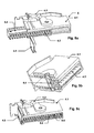
- FIG. 5 shows the assembly and the plugged-in connector, partly in section
- FIG. 6 shows a detail from FIG. 5
- FIG. 7 shows a detailed view of the area where contact is made while omitting the other parts of the connector
- FIG. 8 a shows an edge connector whose contact surfaces extend up to the edge of the contact area
- FIG. 8 b shows an edge connector whose contact surfaces are placed further back from the edge
- FIG. 9 shows a configuration of the connector where the carrier of the contact elements can be inserted
- FIG. 10 shows a configuration of the connector with an alternative carrier for other contact elements
- FIG. 11 is another section of the assembly in the area of the contacting chamber providing a view at the inner wall.
- FIG. 1 is an exploded diagram showing the components of the assembly prior to mounting.
- the assembly consists of a housing comprising an upper housing part 1 and a lower housing part 2 ; the terms “upper” and “lower” are used in connection with the description according to the view shown in FIG. 1 and it is not essential to the invention which housing part is in fact arranged on top or below the other and, in particular, where the connector area is formed.
- the exemplary embodiments shown and described herein are merely exemplary and do not limit the invention.
- the connector area 1 . 1 is located on the upper housing part 1 .
- the lower housing part 2 is designed as a lid comprising an inner wall 2 . 1 that serves to form the contacting chamber 1 . 3 , which is placed further back (cf. following figures), and a projection 2 . 2 that serves to close the contacting chamber 1 . 3 in the direction of the bottom side of the housing.
- the circuit board 3 is arranged between the upper housing part 1 and the lower housing part 2 , wherein a tongue-shaped contacting area 3 . 1 is formed on the circuit board, enabling a spatial separation of the contacting area from the other parts of the circuit board 3 and the electrical components 3 . 2 arranged thereon.
- FIG. 2 shows the components of the assembly according to FIG. 1 seen from the opposite direction.
- the figure clearly shows the inner wall 1 . 2 in the upper housing part 1 (located below in FIG. 2 !).
- Said inner wall 1 . 2 divides the upper housing part 1 into an inner chamber 1 . 5 and the contacting chamber 1 . 3 .
- the opening 1 . 4 of the upper housing part 1 is dimensioned in such a manner that the circuit board 3 , including the contact area 3 . 1 located opposite, can be directly inserted into the upper housing part 1 at right angles or the upper housing part 1 can be placed directly on top since the contacting area 3 . 1 is arranged in the contacting chamber 1 . 3 , i.e. placed further back from the outer connector area 1 . 1 .
- FIG. 3 shows a horizontal section of the assembly once it has been mounted to the circuit board 3 .
- the upper housing part 1 is divided so as to form the inner chamber 1 . 5 where the electronic components 3 . 2 are always separated and protected from the environment by the inner wall 1 . 2 , even when the connector is not plugged in.
- FIG. 11 also shows very clearly that both inner walls 1 . 2 and 2 . 1 extend up to the circuit board 3 enclosed between them, thus separating the contacting chamber from the inner chamber.
- the inner walls 2 . 1 and 1 are very clearly that both inner walls 1 . 2 and 2 . 1 extend up to the circuit board 3 enclosed between them, thus separating the contacting chamber from the inner chamber.
- the inner walls 2 . 1 and 1 . 2 also form a unit in terms of material with the plastic material of the upper housing part 1 and the lower housing part 2 , respectively; they are preferably formed integrally therewith so as to extend therefrom or made by two-component moulding, i.e. from another plastic material but bonded thereto during the injection and pressing process.
- each of the edges of the inner walls 2 . 1 and 1 . 2 that are supported by the circuit board can also be provided with a sealing element.
- said sealing elements can also have an excess dimension in the non-mounted state, which will be reduced when the housing is mounted and the two housing parts are pressed against each other and against the circuit board arranged between them, thus achieving a particularly tight seal.
- Only the contacting area 3 . 1 of the circuit board 3 is arranged in the contacting chamber 1 . 3 and may be exposed to the environment through the front opening 1 . 1 . 3 of the connector area 1 . 1 when the connector is not plugged in.
- the vertical section shown in FIG. 4 is a supplementary illustration showing very clearly the interaction of the inner wall 1 . 2 of the upper housing part 1 with the side wall 2 . 1 of the lower housing part 2 , between which the circuit board 3 is protected from the environment in the inner chamber 1 . 5 once the assembly has been mounted.
- the opening 1 . 4 on the bottom side of the upper housing part is dimensioned in such a manner that the circuit board 3 can be directly inserted at right angles.
- the opening 1 . 4 is completely closed by the lower housing part 2 , in particular the projection 2 . 2 , even in the area of the contacting chamber 1 . 3 .
- FIG. 5 shows the assembly and the plugged-in connector 4 , partly in section
- FIG. 6 is an enlarged view showing the area of electrical contact marked by the dotted line in FIG. 5 ; reference will mainly be made to this figure.
- these figures show the interaction of the inner wall 1 . 2 of the upper housing part 1 with the side wall 2 . 1 on the lower housing part 2 to form the inner chamber 1 . 5 for the electrical components 3 . 2 on the circuit board 3 and the separate contacting chamber 1 . 3 .
- the carrier 4 . 4 of the connector 4 encloses the contacting area 3 . 1 of the circuit board 3 on both sides while inside the contact elements 4 . 2 of the connector 4 are in electrical contact with the contact surfaces 3 . 1 . 1 , as can be seen even better in FIG. 7 .
- FIG. 7 shows only the circuit board 3 including the contact surfaces 3 . 1 . 1 and the insulating gaps 3 . 1 . 2 between them and a preferred configuration of a contact element 4 . 2 while omitting all housings of the assembly as well as the connector, so that the way electrical contact is actually made can be seen.
- a connector preferably comprises a plurality of identical contact elements 4 . 2 .
- Each contact element 4 . 2 comprises a resilient arm including an insertion area 4 . 2 . 1 , which is slightly wider than the thickness of the circuit board 3 and opens so as to extend away from the circuit board, a contact area 4 . 2 . 2 of the resilient arm, which is narrower than said insertion area and possibly with light press fit on the circuit board 3 , and preferably an opposite arm 4 . 2 . 3 for exerting counterpressure, wherein the opposite arm 4 . 2 . 3 can be rigid or be a resilient arm of identical design.
- each contact element 4 . 2 has a connection zone 4 . 2 . 4 where the contact element 4 . 2 is connected to electrical connection cables (not shown in detail) in the connector 4 .
- FIGS. 8 a and 8 b outline different configurations of the edge connection, which—as mentioned above—is preferred for the invention, wherein in FIG. 8 a the contact surfaces 3 . 1 . 1 extend up to the edge 3 . 1 . 3 of the contact area 3 . 1 , possibly even continuing around said edge 3 . 1 . 3 and continuously electrically connected down to the bottom side of the circuit board 3 .
- the contact surfaces 3 . 1 . 1 can of course be arranged at a certain distance from the edge 3 . 1 . 3 .
- FIGS. 9 a , 9 b and 9 c show a particularly preferred configuration of the connector 4 .
- the connector 4 consists of an outer connector frame 4 . 1 formed in accordance with the connector area 1 . 1 and into which a separate carrier 4 . 4 including the contact elements 4 . 2 can preferably be inserted.
- the carrier 4 . 4 can be locked in the connector frame 4 . 1 by means of a closure plate 4 . 5 .
- the particular advantage of such a connector with a separate carrier 4 . 4 will be seen when looking at FIG. 10 as well, where an alternative carrier 4 . 4 including conventional contacts for pin contacts is inserted. This means, one connector 4 and exchangeable carriers 4 . 4 can be used to connect different assemblies.
- a locking element 4 . 3 is preferably formed on the connector 4 , which locking element additionally presses the connector 4 against the housing and locks it to the housing once it has been plugged in.
- the desired moisture-proof assembly-connector unit will remain unaffected by vibrations during driving when such an assembly is used in a motor vehicle, for example as a control unit for engine controls, ABS controls or air bag controls.
Landscapes
- Engineering & Computer Science (AREA)
- Microelectronics & Electronic Packaging (AREA)
- Mechanical Engineering (AREA)
- Manufacturing & Machinery (AREA)
- Connector Housings Or Holding Contact Members (AREA)
- Coupling Device And Connection With Printed Circuit (AREA)
- Motor Or Generator Frames (AREA)
Applications Claiming Priority (4)
| Application Number | Priority Date | Filing Date | Title |
|---|---|---|---|
| DE102010025086 | 2010-06-25 | ||
| DE102010025086A DE102010025086A1 (de) | 2010-06-25 | 2010-06-25 | Verfahren zur elektrischen Kontaktierung einer elektrischen Baugruppe für ein Kraftfahrzeug mit zumindest einem Stecker |
| DE102010025086.4 | 2010-06-25 | ||
| PCT/DE2011/001450 WO2012010152A2 (fr) | 2010-06-25 | 2011-06-22 | Ensemble électrique pour un véhicule automobile, approprié pour la connexion avec un connecteur |
Publications (2)
| Publication Number | Publication Date |
|---|---|
| US20130100620A1 US20130100620A1 (en) | 2013-04-25 |
| US8885353B2 true US8885353B2 (en) | 2014-11-11 |
Family
ID=44789254
Family Applications (1)
| Application Number | Title | Priority Date | Filing Date |
|---|---|---|---|
| US13/805,856 Expired - Fee Related US8885353B2 (en) | 2010-06-25 | 2011-06-22 | Electrical assembly for a motor vehicle, suitable for contacting with a connector |
Country Status (6)
| Country | Link |
|---|---|
| US (1) | US8885353B2 (fr) |
| EP (1) | EP2586280B1 (fr) |
| KR (1) | KR20130122719A (fr) |
| CN (1) | CN102986315B (fr) |
| DE (3) | DE102010025086A1 (fr) |
| WO (2) | WO2011160620A2 (fr) |
Cited By (2)
| Publication number | Priority date | Publication date | Assignee | Title |
|---|---|---|---|---|
| US20180370462A1 (en) * | 2017-06-27 | 2018-12-27 | Iconn Systems, Llc | Electric power distribution module and system |
| US11293269B2 (en) * | 2017-11-06 | 2022-04-05 | Weatherford Technology Holdings, Llc | Control system for hydrocarbon recovery tools |
Families Citing this family (11)
| Publication number | Priority date | Publication date | Assignee | Title |
|---|---|---|---|---|
| JP5330173B2 (ja) * | 2009-09-24 | 2013-10-30 | 矢崎総業株式会社 | 機器接続用コネクタ |
| FR2979859B1 (fr) * | 2011-09-13 | 2014-01-31 | Delphi Tech Inc | Module de controle integrant un dispositif d'aide a l'assemblage. |
| DE102012102849A1 (de) * | 2012-04-02 | 2013-10-02 | Phoenix Contact Gmbh & Co. Kg | Befestigung und Abdichtung eines Steckanschlussmoduls in einer Gehäusewandung |
| JP6071239B2 (ja) * | 2012-04-19 | 2017-02-01 | 矢崎総業株式会社 | 車載用電子機器の防湿構造 |
| CN103838342A (zh) * | 2012-11-23 | 2014-06-04 | 鸿富锦精密工业(深圳)有限公司 | 电源 |
| DE102012222674A1 (de) * | 2012-12-10 | 2014-06-12 | Robert Bosch Gmbh | Elektronische Anordnung mit Leiterplatte |
| DE102013223309A1 (de) * | 2012-12-10 | 2014-06-12 | Robert Bosch Gmbh | Steuergerät für ein Kraftfahrzeug |
| DE102013113200A1 (de) * | 2013-11-28 | 2015-05-28 | Huf Hülsbeck & Fürst Gmbh & Co. Kg | Gehäuse für wenigstens ein elektrisches Bauteil |
| US10028411B2 (en) * | 2016-07-26 | 2018-07-17 | Continental Automotive Systems, Inc. | Electronic controller with laser weld sealed housing |
| DE102019135429A1 (de) * | 2019-12-20 | 2021-06-24 | Hanon Systems | Gehäuse zur Aufnahme einer Leiterplatine |
| DE102021209611A1 (de) | 2021-09-01 | 2023-03-02 | Brose Fahrzeugteile SE & Co. Kommanditgesellschaft, Coburg | Steckverbindungseinrichtung für ein Kraftfahrzeug |
Citations (9)
| Publication number | Priority date | Publication date | Assignee | Title |
|---|---|---|---|---|
| US4596436A (en) | 1985-03-25 | 1986-06-24 | Amp Incorporated | Electrical connector housing assembly comprising housing frame containing housing modules |
| DE4005113A1 (de) | 1990-02-17 | 1991-08-22 | Bosch Gmbh Robert | Dickschichthybridbaugruppe mit einem steckanschluss |
| EP0712265A1 (fr) | 1994-11-08 | 1996-05-15 | TEMIC TELEFUNKEN microelectronic GmbH | Assemblage électronique |
| DE19533723A1 (de) | 1995-09-12 | 1997-03-13 | Whitaker Corp | Anordnung mit einem zweiteiligen Gehäuse und mindestens einem Steckeranschluß, sowie Verfahren zur Herstellung einer solchen Anordnung |
| EP1104228A2 (fr) | 1999-11-25 | 2001-05-30 | DaimlerChrysler AG | Boítier plastique pour recevoir un ensemble constructif de composants électriques et électroniques montés sur un circuit imprimé |
| US6606252B1 (en) * | 2002-07-17 | 2003-08-12 | Delphi Technologies, Inc. | Fastener detection for encased electrical assembly |
| US6781847B2 (en) * | 2001-04-27 | 2004-08-24 | Robert Bosch Gmbh | Housing for an electric device |
| DE102004002562A1 (de) | 2004-01-17 | 2005-08-04 | Conti Temic Microelectronic Gmbh | Strahlungsschützendes Bechergehäuse für eine elektrische Baugruppe mit einem Schaltungsträger |
| DE102005003448A1 (de) | 2005-01-25 | 2006-08-03 | Siemens Ag | Systemkomponente eines Steuergerätes |
Family Cites Families (2)
| Publication number | Priority date | Publication date | Assignee | Title |
|---|---|---|---|---|
| DE102004017605B3 (de) * | 2004-04-07 | 2005-10-20 | Adc Gmbh | Steckverbinder für Leiterplatten sowie Verteileranschlussmodul |
| DE102007010009B4 (de) * | 2007-03-01 | 2019-01-31 | Continental Automotive Gmbh | Steuergerät für ein Kraftfahrzeug |
-
2010
- 2010-06-25 DE DE102010025086A patent/DE102010025086A1/de not_active Withdrawn
-
2011
- 2011-06-22 CN CN201180031334.XA patent/CN102986315B/zh not_active Expired - Fee Related
- 2011-06-22 EP EP11767898.7A patent/EP2586280B1/fr not_active Not-in-force
- 2011-06-22 US US13/805,856 patent/US8885353B2/en not_active Expired - Fee Related
- 2011-06-22 WO PCT/DE2011/001358 patent/WO2011160620A2/fr active Application Filing
- 2011-06-22 WO PCT/DE2011/001450 patent/WO2012010152A2/fr active Application Filing
- 2011-06-22 KR KR1020137001992A patent/KR20130122719A/ko not_active Application Discontinuation
- 2011-06-22 DE DE112011100123T patent/DE112011100123A5/de not_active Withdrawn
- 2011-06-22 DE DE112011100137T patent/DE112011100137A5/de not_active Withdrawn
Patent Citations (13)
| Publication number | Priority date | Publication date | Assignee | Title |
|---|---|---|---|---|
| US4596436A (en) | 1985-03-25 | 1986-06-24 | Amp Incorporated | Electrical connector housing assembly comprising housing frame containing housing modules |
| DE3609684A1 (de) | 1985-03-25 | 1986-09-25 | Amp Inc., Harrisburg, Pa. | Gehaeuseanordnung fuer elektrische verbinder |
| DE4005113A1 (de) | 1990-02-17 | 1991-08-22 | Bosch Gmbh Robert | Dickschichthybridbaugruppe mit einem steckanschluss |
| EP0712265A1 (fr) | 1994-11-08 | 1996-05-15 | TEMIC TELEFUNKEN microelectronic GmbH | Assemblage électronique |
| US6233153B1 (en) | 1994-11-08 | 2001-05-15 | Temic Telefunken Microelectronic Gmbh | Subassembly having a housing with an integral electrical plug unit |
| DE19533723A1 (de) | 1995-09-12 | 1997-03-13 | Whitaker Corp | Anordnung mit einem zweiteiligen Gehäuse und mindestens einem Steckeranschluß, sowie Verfahren zur Herstellung einer solchen Anordnung |
| EP1104228A2 (fr) | 1999-11-25 | 2001-05-30 | DaimlerChrysler AG | Boítier plastique pour recevoir un ensemble constructif de composants électriques et électroniques montés sur un circuit imprimé |
| US6445568B1 (en) | 1999-11-25 | 2002-09-03 | Daimlerchrysler Ag | Plastic housing with condensation protection for electric and electronic assemblies |
| US6781847B2 (en) * | 2001-04-27 | 2004-08-24 | Robert Bosch Gmbh | Housing for an electric device |
| US6606252B1 (en) * | 2002-07-17 | 2003-08-12 | Delphi Technologies, Inc. | Fastener detection for encased electrical assembly |
| DE102004002562A1 (de) | 2004-01-17 | 2005-08-04 | Conti Temic Microelectronic Gmbh | Strahlungsschützendes Bechergehäuse für eine elektrische Baugruppe mit einem Schaltungsträger |
| DE102005003448A1 (de) | 2005-01-25 | 2006-08-03 | Siemens Ag | Systemkomponente eines Steuergerätes |
| US7885080B2 (en) | 2005-01-25 | 2011-02-08 | Continental Automotive Gmbh | System component of a control device |
Non-Patent Citations (3)
| Title |
|---|
| German Search Report for German Application No. 10 2010 025 086.4, dated Jun. 20, 2011, 5 pages, Muenchen, Germany, with English translation, 5 pages. |
| International Search Report of the International Searching Authority for International Application PCT/DE2011/001450, mailed Mar. 12, 2012, 3 pages, European Patent Office, HV Rijswijk, Netherlands. |
| PCT International Preliminary Report on Patentability including English Translation of PCT Written Opinion of the International Searching Authority for International Application PCT/DE2011/001450, issued Dec. 28, 2012, 9 pages, International Bureau of WIPO, Geneva, Switzerland. |
Cited By (2)
| Publication number | Priority date | Publication date | Assignee | Title |
|---|---|---|---|---|
| US20180370462A1 (en) * | 2017-06-27 | 2018-12-27 | Iconn Systems, Llc | Electric power distribution module and system |
| US11293269B2 (en) * | 2017-11-06 | 2022-04-05 | Weatherford Technology Holdings, Llc | Control system for hydrocarbon recovery tools |
Also Published As
| Publication number | Publication date |
|---|---|
| WO2012010152A2 (fr) | 2012-01-26 |
| EP2586280B1 (fr) | 2016-05-04 |
| US20130100620A1 (en) | 2013-04-25 |
| DE112011100123A5 (de) | 2012-09-20 |
| WO2011160620A2 (fr) | 2011-12-29 |
| WO2012010152A3 (fr) | 2012-05-10 |
| CN102986315A (zh) | 2013-03-20 |
| EP2586280A2 (fr) | 2013-05-01 |
| DE102010025086A1 (de) | 2011-12-29 |
| CN102986315B (zh) | 2016-02-24 |
| WO2011160620A3 (fr) | 2012-05-03 |
| DE112011100137A5 (de) | 2012-10-31 |
| KR20130122719A (ko) | 2013-11-08 |
Similar Documents
| Publication | Publication Date | Title |
|---|---|---|
| US8885353B2 (en) | Electrical assembly for a motor vehicle, suitable for contacting with a connector | |
| US9761988B1 (en) | Waterproof electric connector assembly | |
| US9455538B2 (en) | Card edge connector | |
| US7628654B2 (en) | Card edge connector and method of manufacturing the same | |
| US7748988B2 (en) | Card edge connector and method of manufacturing the same | |
| US20050174748A1 (en) | Electronic control device | |
| CN111510591B (zh) | 摄像头模块和用于车辆的摄像头 | |
| US9461385B2 (en) | Card edge connector | |
| CN106025680B (zh) | 电接线盒 | |
| AU2010348146A1 (en) | Housing base element of a multi-part housing and method for assembly of a housing | |
| US20170194750A1 (en) | Electrical connector with device securing shielding plate and insulator together before molding | |
| US10729021B1 (en) | Capped electronic control unit | |
| US20070049111A1 (en) | Electrical plug-and-socket connector | |
| KR100272910B1 (ko) | 압력 보상 소자 및 터미날 스트립 | |
| JP2011028856A (ja) | 電子装置 | |
| JPH08185920A (ja) | 回路基板の電気的接続構造 | |
| WO2014103403A1 (fr) | Connecteur de bord de carte | |
| JP2015088233A (ja) | コネクタ | |
| CN101258650A (zh) | 带有电构件和电馈线的壳体 | |
| US11056810B2 (en) | Circuit board with a plug connection | |
| TW201838259A (zh) | 電連接器 | |
| KR20180051943A (ko) | 전자 제어 장치 | |
| US10186796B2 (en) | Connector unit, sub-connector with frame and sub-connector with cap | |
| KR102397522B1 (ko) | 커넥터 어셈블리 | |
| EP3680988B1 (fr) | Appareil électrique ayant une fonction de connexion et de protection électriques |
Legal Events
| Date | Code | Title | Description |
|---|---|---|---|
| AS | Assignment |
Owner name: CONTINENTAL AUTOMOTIVE GMBH, GERMANY Free format text: ASSIGNMENT OF ASSIGNORS INTEREST;ASSIGNORS:CHRISTOPH, MARKUS;PLANKL, CHRISTIAN;WOERLE, ENGELBERT;AND OTHERS;SIGNING DATES FROM 20121130 TO 20121213;REEL/FRAME:029510/0372 |
|
| STCF | Information on status: patent grant |
Free format text: PATENTED CASE |
|
| FEPP | Fee payment procedure |
Free format text: PAYOR NUMBER ASSIGNED (ORIGINAL EVENT CODE: ASPN); ENTITY STATUS OF PATENT OWNER: LARGE ENTITY |
|
| MAFP | Maintenance fee payment |
Free format text: PAYMENT OF MAINTENANCE FEE, 4TH YEAR, LARGE ENTITY (ORIGINAL EVENT CODE: M1551) Year of fee payment: 4 |
|
| FEPP | Fee payment procedure |
Free format text: MAINTENANCE FEE REMINDER MAILED (ORIGINAL EVENT CODE: REM.); ENTITY STATUS OF PATENT OWNER: LARGE ENTITY |
|
| LAPS | Lapse for failure to pay maintenance fees |
Free format text: PATENT EXPIRED FOR FAILURE TO PAY MAINTENANCE FEES (ORIGINAL EVENT CODE: EXP.); ENTITY STATUS OF PATENT OWNER: LARGE ENTITY |
|
| STCH | Information on status: patent discontinuation |
Free format text: PATENT EXPIRED DUE TO NONPAYMENT OF MAINTENANCE FEES UNDER 37 CFR 1.362 |
|
| FP | Lapsed due to failure to pay maintenance fee |
Effective date: 20221111 |