US8822845B2 - Cable sleeve for a hand-held power tool - Google Patents
Cable sleeve for a hand-held power tool Download PDFInfo
- Publication number
- US8822845B2 US8822845B2 US13/000,694 US200913000694A US8822845B2 US 8822845 B2 US8822845 B2 US 8822845B2 US 200913000694 A US200913000694 A US 200913000694A US 8822845 B2 US8822845 B2 US 8822845B2
- Authority
- US
- United States
- Prior art keywords
- cable
- cable sleeve
- housing
- sleeve
- recited
- Prior art date
- Legal status (The legal status is an assumption and is not a legal conclusion. Google has not performed a legal analysis and makes no representation as to the accuracy of the status listed.)
- Active, expires
Links
Images


Classifications
-
- B—PERFORMING OPERATIONS; TRANSPORTING
- B25—HAND TOOLS; PORTABLE POWER-DRIVEN TOOLS; MANIPULATORS
- B25F—COMBINATION OR MULTI-PURPOSE TOOLS NOT OTHERWISE PROVIDED FOR; DETAILS OR COMPONENTS OF PORTABLE POWER-DRIVEN TOOLS NOT PARTICULARLY RELATED TO THE OPERATIONS PERFORMED AND NOT OTHERWISE PROVIDED FOR
- B25F5/00—Details or components of portable power-driven tools not particularly related to the operations performed and not otherwise provided for
Definitions
- the present invention is based on a cable sleeve for guiding a cable in the inlet and outlet region of a hand-held tool.
- Corded hand-held power tools can usually be connected to a power source by means of a cable.
- the cable is encompassed by an essentially coaxial cable sleeve at the cable outlet opening from the housing.
- the cable sleeve assures a relatively low bending angle of the cable at the outlet opening of the housing under all operating conditions, thus preventing a sharp bending of the cable went corresponding forces are exerted on it. This protects the cable from being damaged by extreme bending and also from other mechanical influences in the region in which it is enclosed by the cable sleeve.
- the cooling air of the electric motor is usually drawn into the housing from the outside through inlet openings, travels past the motor, and is blown out again through outlet openings.
- negative pressure is produced in the housing, which causes air from the outside to flow into the housing through all existing openings and gaps in corresponding regions, including through the gap between the cable and cable sleeve.
- This gap is present due to the relatively high production tolerances of the cable and cable sleeve and due to the fact that only a few types of cable sleeve are used for a wide variety of cables of different external diameters that are required due to the various voltage systems worldwide. For this reason, it is currently necessary to stock a plurality of cable sleeve types with various inner diameters.
- Air drawn in by means of the cable sleeve conveys dust particles from the work environment into the interior of the power tool.
- these dust particles are frequently metallic and on the inside of the housing, can settle on switches or other electrical, voltage-carrying elements.
- the conductive metallic particles can form bridges between the different voltage potentials.
- Corresponding arcing can result in breakdowns of the hand-held power tool and can be hazardous to the user.
- the invention can perform a sealing action and can provide tolerance compensation. It is therefore not necessary to use a specific cable sleeve type for each country-specific design of the hand-held power tool, thus reducing the number of parts required.
- the cable sleeve can simultaneously function as a power cord strain-relief element.
- the cable sleeve encompasses the cable in a radially sealed, frictional, nonpositive fashion, water, dust, and the like cannot penetrate into the interior of the housing, particularly because the end of the cable sleeve oriented toward the housing has a ring-like sealing element that rests in a sealed fashion against the outer circumference of the cable.
- the cable sleeve is provided with a helical sealing lip that protrudes radially inward, the cable can be inserted axially into a narrow cable sleeve by turning it like a screw.
- the sealing action is improved by virtue of the fact that the cable sleeve has a plurality of ring-like sealing elements at its end oriented toward the housing.
- the sealing action can be improved and the manufacture of the cable sleeve can be simplified by virtue of the fact that the ring-like sealing elements are embodied in the form of annular beads, particularly in the form of injection-molded O-rings composed of a material that differs from the material of the sleeve, in particular has softer elastic properties than it.
- the sealing action for particular circumstances and special applications can be improved by virtue of the fact that the ring-like sealing elements are embodied in the form of hollow cylindrical plugs, in particular wedge-shaped plugs, that protrude into the hollow cylinder of the cable sleeve, particularly at its front end.
- Another easy-to-install sealing variant is achieved by virtue of the fact that a smooth, cylindrical, hollow connecting piece of the cable sleeve protrudes axially into the interior of the housing and in the installed position therein, is encompassed in a contracting fashion so that a region of the hollow connecting piece rests in an annular, sealed fashion against the outside of the cable.
- the sealing action can be improved with extremely simple means by virtue of the fact that the housing is composed of housing shells, each of which has a clamping jaw-like part that belongs to a respective housing shell.
- the sealing action can be improved with even simpler means by virtue of the fact that an annular shell part, in particular belonging to the housing, is able to act on the hollow connecting piece in the radial direction.
- annular shell-like part is embodied in the form of a tension sling, in particular a twistable wire and/or pipe clamp and/or cable strap.
- FIG. 1 shows a longitudinal sections through a hand-held power tool housing equipped with the cable and cable sleeve according to the invention
- FIG. 2 shows another longitudinal section through the hand-held power tool housing equipped with the cable and cable sleeve according to the invention
- FIG. 3 shows the cable sleeve according to FIGS. 1 and 2 , in a longitudinal section through a detail
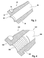
- FIG. 4 shows another cable sleeve with a helical radial inner sealing lip
- FIGS. 5 and 6 each show a variant of the cable sleeve with a plurality of radial inner sealing lips
- FIG. 7 shows a cable sleeve with a hollow, cylindrical plug as a sealing means
- FIG. 8 shows a cable sleeve with a crushing region, which, acting as a sealing means, is acted on by clamping jaws,
- FIG. 9 shows a cable sleeve with a crushing region, which, acting as a sealing means, is acted on by an annular bracket-like sleeve.
- a cable sleeve 22 depicted in FIGS. 1 , 2 , and 3 has an annular, circumferential, inward-oriented radial sealing lip 28 that encompasses a cable, which is pulled into it, in an elastically pressing and therefore axially sealed fashion; the hollow cylinder 26 has a conical wall that becomes thinner toward its end 32 , which encompasses the cable 36 and shields it from the outside.
- the significantly thicker wall region in the vicinity of the front end 30 absorbs a greater bending moment than closer to the end 32 and therefore in the event of powerful bending forces acting on the cable 36 , prevents a sharp bending of the cable 36 relative to the longitudinal axis 24 of the housing 10 , i.e. by an acute angle of approximately 90° with a minimal bending radius, and thus also prevents breakage of the cable strands inside the cable 36 .
- the cable sleeve 22 is conventionally embodied and can be fixed in position by means of an external annular groove 34 , which is associated with a matching annular projection 16 of the housing 10 , and by means of its front end 30 , which is associated with a rib-like axial stop 18 of the housing 10 .
- the housing wall 11 of housing 10 constitutes a cable sleeve outlet opening 14 , which encompasses the cable sleeve 22 through which the cable sleeve 22 protrudes outward, and as it does so, conveys the cable 36 to the inside.
- the sealing, insertion, and withdrawal properties of the cable in relation to the cable sleeve 22 can be selected through the embodiment of the sleeve's angle in the region of the sealing lip. If the sealing lip 28 , as depicted in FIG. 3 , has a saw-tooth structure, it is safe to assume that the cable sleeve 22 has a relatively low, assembly-friendly cable pull-in force as compared to a higher pull-out force. This facilitates strain relief. To this end, it is also possible to provide corresponding grooves or cams on the cable 36 .
- FIG. 4 shows a cable sleeve 220 having a front end 300 and an end 320 .
- the cable sleeve 220 is provided with a helical inward-oriented radial sealing lip 280 that can have a stepped inner diameter for a use with cables of different diameters.
- sealing lips that are too tight can be removed mechanically or thermally or in some other way.
- the cable 36 is screwed into the cable sleeve 220 like a screw into the thread of a nut.
- a cable sleeve 220 that is manufactured in one piece to have material combinations between the conventional sleeve region and the sealing region.
- the cable sleeves 2200 , 22000 shown in FIGS. 5 and 6 each have two parallel, radial, inner sealing lips 2800 , 28000 constituted by integrated annular beads or O-rings composed of a material that is the same as or different from the material of the respective cable sleeve.
- these can each have a different respective inner diameter for different thicknesses of cable; for thicker cables, excessively tight sealing lips can be removed mechanically or thermally or in some other way.
- a cable that has been pulled in is elastically enclosed in a sealed fashion in accordance with the active principle of an O-ring.
- Other shapes of the annular bead—e.g. rectangular, square, or elliptical—and/or other materials of a one-piece cable sleeve for the conventional sleeve region and the sealing region are also conceivable.
- the advantage of this variant is the ability to select a suitable size of the O-rings; it is also possible to select from a broad range of materials for the sealing means.
- the sealing cross-sections it is also advantageous for the sealing cross-sections to be embodied as rectangular, square, elliptical, saw-toothed, etc.
- the front end 301 of the cable sleeve 221 shown in FIG. 7 has an elastic, hollow, cylindrical wedge element 281 that is pressed into the inside of the hollow cylinder 263 of the cable sleeve 221 and correspondingly fixed in place, e.g. by means of frictional, nonpositive engagement, a mechanical undercut, a rib on the housing, or glue.
- the pressing action slides the wedge element in a sealed fashion into the pre-existing gap between the cable sleeve and the cable, not shown.
- Another variant of a cable sleeve manufactured of one piece in accordance with the design shown in FIG. 7 , equipped with an integrated cone, is not shown in the drawing.
- the front end 302 of the cable sleeve 222 shown in FIG. 8 has a protruding region 29 similar to a pipe-connecting piece, with a narrow wall thickness.
- This region 29 performs its sealing function in relation to an inserted cable once a radial force is exerted on it from the outside.
- opposing ribs 13 are integrated into the two shells 12 (one shell 12 is shown in FIG. 1 ) of the housing 10 and when the shells 12 are assembled, act on the region 13 from the outside like a pair of pliers, deforming it in a cross-sectionally constricting fashion, producing a seal in relation to the inserted cable.
- a plurality of ribs may be arranged one after another and laterally offset from one another, from the one shell to the other shell.
- the additional deformation of the power cord could function like a strain-relief element.
- the front end 303 of the cable sleeve 223 shown in FIG. 9 has a protruding region 291 similar to a pipe connecting piece, with a narrow wall thickness like the cable sleeve according to FIG. 8 .
- This region 291 performs its sealing function in relation to an inserted cable once a radial force is exerted on it from the outside.
- a crushing element 11 is provided, which acts on the region 13 from the outside, deforming it in a cross-sectionally constricting fashion, producing a seal in relation to an inserted cable.
- the crushing element can, for example, be a twistable wire, pipe clamp, cable strap, or similar device. According to this principle, the seal is achieved by compressing and constricting the sleeve from the outside in the direction toward the power cord. Another advantage is the possibility of prefabricating the combined unit composed of the sleeve and cable.
- gluing the cable sleeve to the cable would produce a sealed, strain-relieving cable inlet. Filling the intermediate space between the cable sleeve and cable with a corresponding foam material is also a conceivable way to achieve a durable, sealed connection.
- a cable sleeve that is vulcanized onto the cable is provided and/or the cable sleeve is injection molded around the cable and/or the cable sleeve is embodied in the form of an elastic shrink sleeve.
- the cable sleeves can also be embodied of multiple parts or in the form of shells in order to facilitate assembly.
Landscapes
- Engineering & Computer Science (AREA)
- Mechanical Engineering (AREA)
- Installation Of Indoor Wiring (AREA)
- Cable Accessories (AREA)
- Insulating Bodies (AREA)
Applications Claiming Priority (4)
| Application Number | Priority Date | Filing Date | Title |
|---|---|---|---|
| DE102008002616 | 2008-06-24 | ||
| DE102008002616.6 | 2008-06-24 | ||
| DE102008002616A DE102008002616A1 (de) | 2008-06-24 | 2008-06-24 | Kabeltülle für Handwerkzeugmaschine |
| PCT/EP2009/054965 WO2009156206A1 (de) | 2008-06-24 | 2009-04-24 | Kabeltülle für handwerkzeugmaschine |
Publications (2)
| Publication Number | Publication Date |
|---|---|
| US20110100708A1 US20110100708A1 (en) | 2011-05-05 |
| US8822845B2 true US8822845B2 (en) | 2014-09-02 |
Family
ID=40921962
Family Applications (1)
| Application Number | Title | Priority Date | Filing Date |
|---|---|---|---|
| US13/000,694 Active 2030-11-12 US8822845B2 (en) | 2008-06-24 | 2009-04-24 | Cable sleeve for a hand-held power tool |
Country Status (6)
| Country | Link |
|---|---|
| US (1) | US8822845B2 (ru) |
| EP (1) | EP2303517A1 (ru) |
| CN (1) | CN102076467B (ru) |
| DE (1) | DE102008002616A1 (ru) |
| RU (1) | RU2534700C2 (ru) |
| WO (1) | WO2009156206A1 (ru) |
Cited By (3)
| Publication number | Priority date | Publication date | Assignee | Title |
|---|---|---|---|---|
| US20170322386A1 (en) * | 2014-06-17 | 2017-11-09 | Afl Telecommunications Llc | Optical fiber furcation transition assembly with integrated retention feature |
| US20170324193A1 (en) * | 2013-12-20 | 2017-11-09 | Ppc Broadband, Inc. | Radio frequency (rf) shield for microcoaxial (mcx) cable connectors |
| US20220115813A1 (en) * | 2020-10-12 | 2022-04-14 | Smk Corporation | Floating structure of coaxial connector |
Families Citing this family (14)
| Publication number | Priority date | Publication date | Assignee | Title |
|---|---|---|---|---|
| JP5722638B2 (ja) * | 2010-09-28 | 2015-05-27 | 株式会社マキタ | 充電式電動工具 |
| DE102010043565A1 (de) * | 2010-11-08 | 2012-05-10 | Robert Bosch Gmbh | Befestigungsvorrichtung für eine Leitung und Verfahren zum Befestigen einer Leitung |
| EP2581175B1 (en) * | 2011-10-11 | 2015-05-27 | Black & Decker Inc. | Cord protector for power tools |
| CN103158117B (zh) * | 2011-12-13 | 2016-09-14 | 百得有限公司 | 一种电动工具 |
| EP2869965B1 (en) | 2012-07-04 | 2016-08-17 | Black & Decker Inc. | Power tool |
| DE102012112620A1 (de) * | 2012-12-19 | 2014-06-26 | C. & E. Fein Gmbh | Kabelzugentlastung |
| US9048651B2 (en) * | 2013-02-05 | 2015-06-02 | Bose Corporation | Low-profile strain relief and cable retention |
| CN105143942A (zh) * | 2013-03-13 | 2015-12-09 | 3M创新有限公司 | 线缆入口用密封管 |
| DE102013206810A1 (de) | 2013-04-16 | 2014-10-16 | Ifm Electronic Gmbh | Näherungsschalter |
| US20150138785A1 (en) * | 2013-11-15 | 2015-05-21 | Osram Sylvania Inc. | Enclosure with grommetless strain relief |
| KR101611269B1 (ko) * | 2014-09-15 | 2016-04-12 | 주식회사 케이피씨 | 방수 팬 케이스의 케이블 고정구조 |
| US9769551B2 (en) | 2014-12-31 | 2017-09-19 | Skullcandy, Inc. | Method of connecting cable to headphone, and headphone formed using such methods |
| EP3293496B1 (de) * | 2016-09-12 | 2018-11-21 | Dr. Johannes Heidenhain GmbH | Längenmesseinrichtung und verfahren zu deren montage |
| DE102020004934A1 (de) | 2020-08-13 | 2022-02-17 | Auto-Kabel Management Gmbh | Dichtung für ein elektrisches Kabel |
Citations (59)
| Publication number | Priority date | Publication date | Assignee | Title |
|---|---|---|---|---|
| US1218216A (en) * | 1912-05-17 | 1917-03-06 | Allis Chalmers Mfg Co | Connector. |
| US1912115A (en) * | 1931-07-17 | 1933-05-30 | B F Sturtevant Co | Lead-in device |
| US2386000A (en) * | 1941-06-27 | 1945-10-02 | Belden Mfg Co | Molded strain relief |
| FR1450565A (fr) | 1965-06-02 | 1966-08-26 | Dispositif de raccordement pour installation électrique | |
| DE1290214B (de) | 1964-02-28 | 1969-03-06 | Serlachius Oy | Kabeldurchfuehrung zum Verlegen insbesondere elektrischer Kabel durch Wandungen hindurch |
| US3499097A (en) * | 1968-01-18 | 1970-03-03 | Marathon Electric Mfg | Strain relief for power cord of electrical machine |
| US3744008A (en) * | 1971-11-23 | 1973-07-03 | Thomas & Betts Corp | Strain relief assembly |
| US3946144A (en) * | 1973-06-28 | 1976-03-23 | Wilhelm Quante Spezialmaschinenfabrik Fur Apparate Der Fernmeldetechnik | Sealed cable junction |
| US4002818A (en) * | 1974-07-25 | 1977-01-11 | Siemens Aktiengesellschaft | Lipped cable entry seal for pressurized sleeve |
| US4033535A (en) * | 1973-05-18 | 1977-07-05 | Eaton Corporation | Strain-relief bushing |
| US4089496A (en) * | 1976-06-21 | 1978-05-16 | Nifco Inc. | Cord grommet |
| US4145566A (en) * | 1975-10-23 | 1979-03-20 | Neutrik Aktiengesellschaft | Housing for electrical devices |
| US4157799A (en) * | 1976-11-23 | 1979-06-12 | Hans Simon | Cable grommet with traction relief |
| GB2056191A (en) * | 1979-06-15 | 1981-03-11 | British Engines Ltd | Improvements in, or relating to, cable seals |
| US4350840A (en) * | 1981-03-20 | 1982-09-21 | Ideal Industries, Inc. | Cord grip |
| DE3114419A1 (de) * | 1981-04-06 | 1982-10-21 | Siemens AG, 1000 Berlin und 8000 München | Elektrische leitung mit knickschutztuelle |
| EP0117092A1 (en) * | 1983-02-04 | 1984-08-29 | Minnesota Mining And Manufacturing Company | Plastic core for an elastically shrinkable tubular cover |
| GB2136220A (en) | 1983-03-03 | 1984-09-12 | Bicc Plc | An electric plug assembly |
| DE3409906A1 (de) * | 1984-03-17 | 1985-09-19 | Fa. Carl Freudenberg, 6940 Weinheim | Kabeltuelle |
| US4549038A (en) * | 1983-08-22 | 1985-10-22 | Ideal Industries, Inc. | Cord grip |
| GB2171855A (en) * | 1985-02-26 | 1986-09-03 | Egerton A C Ltd | Cable entry seal |
| US4640479A (en) * | 1983-01-31 | 1987-02-03 | All States Inc. | Strain relief grommet |
| US4686738A (en) * | 1984-09-26 | 1987-08-18 | Elektro-Bladh Ab | Cable lead-in device |
| US4738636A (en) * | 1987-04-13 | 1988-04-19 | Appleton Electric Co. | Strain relief connectors for flexible cord and cable |
| SU1487116A1 (ru) * | 1987-09-16 | 1989-06-15 | Aleksandr N Bobkov | Ввод кабеля |
| SU1492406A1 (ru) | 1987-07-03 | 1989-07-07 | Предприятие П/Я Р-6805 | Герметичный кабельный ввод |
| EP0465261A2 (en) * | 1990-07-04 | 1992-01-08 | Moji & Co., Ltd | Improvements relating to multi-core cable connectors |
| DE4134260A1 (de) | 1991-10-16 | 1993-04-22 | Bettermann Obo Ohg | Hutmutter mit knickschutz |
| GB2268639A (en) * | 1992-06-29 | 1994-01-12 | Cliff Electron Components Ltd | Electrical cable grip |
| WO1994024747A1 (en) | 1993-04-14 | 1994-10-27 | Bowthorpe Plc | Cable sealing and locking device |
| US5371821A (en) * | 1991-06-12 | 1994-12-06 | John Mezzalingua Assoc. Inc. | Fiber optic cable end connector having a sealing grommet |
| US5574819A (en) * | 1993-02-03 | 1996-11-12 | Siemens Aktiengesellschaft | Receptacle for a cable end piece |
| US5640476A (en) * | 1995-07-14 | 1997-06-17 | Siecor Corporation | Guide sleeve for fiber optic cable |
| US5773758A (en) * | 1994-11-07 | 1998-06-30 | Thomson Multimedia S.A. | Device for fitting and gripping of a flexible cable in a cylindrical orifice and high-voltage transformer euipped with this device |
| EP0994544A1 (de) * | 1998-10-15 | 2000-04-19 | Robert Bosch Gmbh | Gehäuseteil mit Aufnahme für eine Kabeltülle |
| US6100472A (en) | 1993-04-14 | 2000-08-08 | Bowthorpe Plc | Cable locking and sealing device |
| US6152639A (en) | 1998-02-26 | 2000-11-28 | Mobiletron Electronics Co., Ltd. | Structure allowing free movement of a cable of an electric tool |
| WO2001039334A1 (en) * | 1999-11-23 | 2001-05-31 | Fokker Elmo B.V. | Electrical connector |
| US6274812B1 (en) * | 1999-12-17 | 2001-08-14 | Avaya Technology Corp. | Cable sealing device system |
| CN2457845Y (zh) | 2000-12-27 | 2001-10-31 | 浙江卧龙科技股份有限公司 | 电器引出线固定装置 |
| US20020020543A1 (en) * | 2000-06-27 | 2002-02-21 | Krall Hans Peter | Apparatus having a cable grommet of uniform flexibility |
| US6353185B1 (en) * | 1999-11-18 | 2002-03-05 | Sumitomo Wiring Systems, Ltd. | Grommet and method of installing said grommet on a panel |
| CN1387286A (zh) | 2001-05-18 | 2002-12-25 | 矢崎总业株式会社 | 接线端子整体密封件 |
| US6608254B1 (en) * | 1999-04-29 | 2003-08-19 | Cables Pirelli | Sealing device of the gland type for a cable |
| EP1359643A1 (fr) * | 2002-05-03 | 2003-11-05 | Legrand | Enveloppe d'appareillage électrique à entrée de câbles, prise de courant et fiche de prise de courant comprenant une telle enveloppe |
| US6672894B2 (en) * | 2002-01-22 | 2004-01-06 | Ludlow Company Lp | Flexible interconnect cable strain relief facility |
| US20040154819A1 (en) * | 2002-11-29 | 2004-08-12 | Sumitomo Wiring Systems, Ltd. | Grommet for a wire harness |
| US6822165B2 (en) * | 2001-05-29 | 2004-11-23 | Yazaki Corporation | Grommet with closed airspace inside thereof |
| US20050226589A1 (en) * | 2002-04-10 | 2005-10-13 | Johannes Hafner | Fiber-optic plug comprising crimped knobs |
| US7251409B2 (en) * | 2005-11-14 | 2007-07-31 | Microsoft Corporation | Cable strain relief design for limited space through-hole applications |
| EP1903226A2 (en) * | 2006-07-19 | 2008-03-26 | Finan.Co S.A.S. di Bruno Barbieri & C. | Sealing element for remote-control wires |
| CN201048268Y (zh) | 2007-05-30 | 2008-04-16 | 上海锐奇工具有限公司 | 一种电缆线保护装置 |
| EP1918053A2 (en) | 2006-10-30 | 2008-05-07 | BLACK & DECKER INC. | Power tool |
| US7579556B2 (en) * | 2004-02-25 | 2009-08-25 | Paul Tapper | Cable entry device comprising means for adjustment |
| US7579557B2 (en) * | 2004-02-25 | 2009-08-25 | Paul Tapper | Cable entry device for easy installation |
| DE102010031304A1 (de) * | 2010-07-14 | 2012-01-19 | Robert Bosch Gmbh | Kabelknickschutzeinheit und Verfahren zur Herstellung derselben |
| US20120015555A1 (en) * | 2009-02-12 | 2012-01-19 | Peter Deimel | Cable connection device, line feedthrough provided therewith, and use thereof |
| US20120231653A1 (en) * | 2011-03-08 | 2012-09-13 | Apple Inc. | Strain-relief members for cables and methods for making the same |
| US8586879B2 (en) * | 2010-07-14 | 2013-11-19 | Robert Bosch Gmbh | Cable kink protection unit and method for producing same |
Family Cites Families (2)
| Publication number | Priority date | Publication date | Assignee | Title |
|---|---|---|---|---|
| SU1467641A1 (ru) * | 1987-01-04 | 1989-03-23 | Запорожский Завод Специального Технологического Оборудования | Кабельный ввод |
| DE19947960A1 (de) * | 1999-10-06 | 2001-04-12 | Bosch Gmbh Robert | Gehäuse eines elektrischen Gerätes, insbesondere eines Elektrowerkzeuges |
-
2008
- 2008-06-24 DE DE102008002616A patent/DE102008002616A1/de active Pending
-
2009
- 2009-04-24 EP EP09769055A patent/EP2303517A1/de not_active Withdrawn
- 2009-04-24 RU RU2011101777/02A patent/RU2534700C2/ru not_active IP Right Cessation
- 2009-04-24 WO PCT/EP2009/054965 patent/WO2009156206A1/de active Application Filing
- 2009-04-24 US US13/000,694 patent/US8822845B2/en active Active
- 2009-04-24 CN CN200980124287.6A patent/CN102076467B/zh active Active
Patent Citations (59)
| Publication number | Priority date | Publication date | Assignee | Title |
|---|---|---|---|---|
| US1218216A (en) * | 1912-05-17 | 1917-03-06 | Allis Chalmers Mfg Co | Connector. |
| US1912115A (en) * | 1931-07-17 | 1933-05-30 | B F Sturtevant Co | Lead-in device |
| US2386000A (en) * | 1941-06-27 | 1945-10-02 | Belden Mfg Co | Molded strain relief |
| DE1290214B (de) | 1964-02-28 | 1969-03-06 | Serlachius Oy | Kabeldurchfuehrung zum Verlegen insbesondere elektrischer Kabel durch Wandungen hindurch |
| FR1450565A (fr) | 1965-06-02 | 1966-08-26 | Dispositif de raccordement pour installation électrique | |
| US3499097A (en) * | 1968-01-18 | 1970-03-03 | Marathon Electric Mfg | Strain relief for power cord of electrical machine |
| US3744008A (en) * | 1971-11-23 | 1973-07-03 | Thomas & Betts Corp | Strain relief assembly |
| US4033535A (en) * | 1973-05-18 | 1977-07-05 | Eaton Corporation | Strain-relief bushing |
| US3946144A (en) * | 1973-06-28 | 1976-03-23 | Wilhelm Quante Spezialmaschinenfabrik Fur Apparate Der Fernmeldetechnik | Sealed cable junction |
| US4002818A (en) * | 1974-07-25 | 1977-01-11 | Siemens Aktiengesellschaft | Lipped cable entry seal for pressurized sleeve |
| US4145566A (en) * | 1975-10-23 | 1979-03-20 | Neutrik Aktiengesellschaft | Housing for electrical devices |
| US4089496A (en) * | 1976-06-21 | 1978-05-16 | Nifco Inc. | Cord grommet |
| US4157799A (en) * | 1976-11-23 | 1979-06-12 | Hans Simon | Cable grommet with traction relief |
| GB2056191A (en) * | 1979-06-15 | 1981-03-11 | British Engines Ltd | Improvements in, or relating to, cable seals |
| US4350840A (en) * | 1981-03-20 | 1982-09-21 | Ideal Industries, Inc. | Cord grip |
| DE3114419A1 (de) * | 1981-04-06 | 1982-10-21 | Siemens AG, 1000 Berlin und 8000 München | Elektrische leitung mit knickschutztuelle |
| US4640479A (en) * | 1983-01-31 | 1987-02-03 | All States Inc. | Strain relief grommet |
| EP0117092A1 (en) * | 1983-02-04 | 1984-08-29 | Minnesota Mining And Manufacturing Company | Plastic core for an elastically shrinkable tubular cover |
| GB2136220A (en) | 1983-03-03 | 1984-09-12 | Bicc Plc | An electric plug assembly |
| US4549038A (en) * | 1983-08-22 | 1985-10-22 | Ideal Industries, Inc. | Cord grip |
| DE3409906A1 (de) * | 1984-03-17 | 1985-09-19 | Fa. Carl Freudenberg, 6940 Weinheim | Kabeltuelle |
| US4686738A (en) * | 1984-09-26 | 1987-08-18 | Elektro-Bladh Ab | Cable lead-in device |
| GB2171855A (en) * | 1985-02-26 | 1986-09-03 | Egerton A C Ltd | Cable entry seal |
| US4738636A (en) * | 1987-04-13 | 1988-04-19 | Appleton Electric Co. | Strain relief connectors for flexible cord and cable |
| SU1492406A1 (ru) | 1987-07-03 | 1989-07-07 | Предприятие П/Я Р-6805 | Герметичный кабельный ввод |
| SU1487116A1 (ru) * | 1987-09-16 | 1989-06-15 | Aleksandr N Bobkov | Ввод кабеля |
| EP0465261A2 (en) * | 1990-07-04 | 1992-01-08 | Moji & Co., Ltd | Improvements relating to multi-core cable connectors |
| US5371821A (en) * | 1991-06-12 | 1994-12-06 | John Mezzalingua Assoc. Inc. | Fiber optic cable end connector having a sealing grommet |
| DE4134260A1 (de) | 1991-10-16 | 1993-04-22 | Bettermann Obo Ohg | Hutmutter mit knickschutz |
| GB2268639A (en) * | 1992-06-29 | 1994-01-12 | Cliff Electron Components Ltd | Electrical cable grip |
| US5574819A (en) * | 1993-02-03 | 1996-11-12 | Siemens Aktiengesellschaft | Receptacle for a cable end piece |
| US6100472A (en) | 1993-04-14 | 2000-08-08 | Bowthorpe Plc | Cable locking and sealing device |
| WO1994024747A1 (en) | 1993-04-14 | 1994-10-27 | Bowthorpe Plc | Cable sealing and locking device |
| US5773758A (en) * | 1994-11-07 | 1998-06-30 | Thomson Multimedia S.A. | Device for fitting and gripping of a flexible cable in a cylindrical orifice and high-voltage transformer euipped with this device |
| US5640476A (en) * | 1995-07-14 | 1997-06-17 | Siecor Corporation | Guide sleeve for fiber optic cable |
| US6152639A (en) | 1998-02-26 | 2000-11-28 | Mobiletron Electronics Co., Ltd. | Structure allowing free movement of a cable of an electric tool |
| EP0994544A1 (de) * | 1998-10-15 | 2000-04-19 | Robert Bosch Gmbh | Gehäuseteil mit Aufnahme für eine Kabeltülle |
| US6608254B1 (en) * | 1999-04-29 | 2003-08-19 | Cables Pirelli | Sealing device of the gland type for a cable |
| US6353185B1 (en) * | 1999-11-18 | 2002-03-05 | Sumitomo Wiring Systems, Ltd. | Grommet and method of installing said grommet on a panel |
| WO2001039334A1 (en) * | 1999-11-23 | 2001-05-31 | Fokker Elmo B.V. | Electrical connector |
| US6274812B1 (en) * | 1999-12-17 | 2001-08-14 | Avaya Technology Corp. | Cable sealing device system |
| US20020020543A1 (en) * | 2000-06-27 | 2002-02-21 | Krall Hans Peter | Apparatus having a cable grommet of uniform flexibility |
| CN2457845Y (zh) | 2000-12-27 | 2001-10-31 | 浙江卧龙科技股份有限公司 | 电器引出线固定装置 |
| CN1387286A (zh) | 2001-05-18 | 2002-12-25 | 矢崎总业株式会社 | 接线端子整体密封件 |
| US6822165B2 (en) * | 2001-05-29 | 2004-11-23 | Yazaki Corporation | Grommet with closed airspace inside thereof |
| US6672894B2 (en) * | 2002-01-22 | 2004-01-06 | Ludlow Company Lp | Flexible interconnect cable strain relief facility |
| US20050226589A1 (en) * | 2002-04-10 | 2005-10-13 | Johannes Hafner | Fiber-optic plug comprising crimped knobs |
| EP1359643A1 (fr) * | 2002-05-03 | 2003-11-05 | Legrand | Enveloppe d'appareillage électrique à entrée de câbles, prise de courant et fiche de prise de courant comprenant une telle enveloppe |
| US20040154819A1 (en) * | 2002-11-29 | 2004-08-12 | Sumitomo Wiring Systems, Ltd. | Grommet for a wire harness |
| US7579556B2 (en) * | 2004-02-25 | 2009-08-25 | Paul Tapper | Cable entry device comprising means for adjustment |
| US7579557B2 (en) * | 2004-02-25 | 2009-08-25 | Paul Tapper | Cable entry device for easy installation |
| US7251409B2 (en) * | 2005-11-14 | 2007-07-31 | Microsoft Corporation | Cable strain relief design for limited space through-hole applications |
| EP1903226A2 (en) * | 2006-07-19 | 2008-03-26 | Finan.Co S.A.S. di Bruno Barbieri & C. | Sealing element for remote-control wires |
| EP1918053A2 (en) | 2006-10-30 | 2008-05-07 | BLACK & DECKER INC. | Power tool |
| CN201048268Y (zh) | 2007-05-30 | 2008-04-16 | 上海锐奇工具有限公司 | 一种电缆线保护装置 |
| US20120015555A1 (en) * | 2009-02-12 | 2012-01-19 | Peter Deimel | Cable connection device, line feedthrough provided therewith, and use thereof |
| DE102010031304A1 (de) * | 2010-07-14 | 2012-01-19 | Robert Bosch Gmbh | Kabelknickschutzeinheit und Verfahren zur Herstellung derselben |
| US8586879B2 (en) * | 2010-07-14 | 2013-11-19 | Robert Bosch Gmbh | Cable kink protection unit and method for producing same |
| US20120231653A1 (en) * | 2011-03-08 | 2012-09-13 | Apple Inc. | Strain-relief members for cables and methods for making the same |
Cited By (6)
| Publication number | Priority date | Publication date | Assignee | Title |
|---|---|---|---|---|
| US20170324193A1 (en) * | 2013-12-20 | 2017-11-09 | Ppc Broadband, Inc. | Radio frequency (rf) shield for microcoaxial (mcx) cable connectors |
| US10374364B2 (en) * | 2013-12-20 | 2019-08-06 | Ppc Broadband, Inc. | Radio Frequency (RF) shield for MicroCoaXial (MCX) cable connectors |
| US20170322386A1 (en) * | 2014-06-17 | 2017-11-09 | Afl Telecommunications Llc | Optical fiber furcation transition assembly with integrated retention feature |
| US10156692B2 (en) * | 2014-06-17 | 2018-12-18 | Afl Telecommunications Llc | Optical fiber furcation transition assembly with integrated retention feature |
| US20220115813A1 (en) * | 2020-10-12 | 2022-04-14 | Smk Corporation | Floating structure of coaxial connector |
| US11569614B2 (en) * | 2020-10-12 | 2023-01-31 | Smk Corporation | Floating structure of coaxial connector |
Also Published As
| Publication number | Publication date |
|---|---|
| CN102076467B (zh) | 2014-12-24 |
| RU2534700C2 (ru) | 2014-12-10 |
| US20110100708A1 (en) | 2011-05-05 |
| EP2303517A1 (de) | 2011-04-06 |
| CN102076467A (zh) | 2011-05-25 |
| RU2011101777A (ru) | 2012-07-27 |
| DE102008002616A1 (de) | 2009-12-31 |
| WO2009156206A1 (de) | 2009-12-30 |
Similar Documents
| Publication | Publication Date | Title |
|---|---|---|
| US8822845B2 (en) | Cable sleeve for a hand-held power tool | |
| US7980885B2 (en) | Plug assembly with strain relief | |
| KR100934916B1 (ko) | 파이프용 접속 장치 | |
| US7008264B2 (en) | Connector for coaxial cable with annularly corrugated outside conductor | |
| US9263867B2 (en) | Clamp ring, cable screw connection and method for assembling a cable screw connection | |
| US6976872B1 (en) | Coaxial connector | |
| US7781685B2 (en) | Kit or set comprising at least two differently dimensioned types of cable glands | |
| US7408122B2 (en) | Cable gland | |
| CA2658099C (en) | Weather resistant electrical connector | |
| US7938674B2 (en) | Cable clamp with clamping element | |
| US6447323B1 (en) | Power source cable connector | |
| US7476128B2 (en) | Anti-twist electrical wiring to a plug | |
| CN102025070B (zh) | 带有集成的电缆夹紧装置的插塞连接器壳体 | |
| KR20070095762A (ko) | 환형의 주름진 동축 케이블용 축방향 압축 전기 접속기 | |
| AU2020101289A4 (en) | Quickly-demountable highly-reliable radio frequency coaxial connector | |
| CN103004045B (zh) | 防水电缆衬垫 | |
| US20050067832A1 (en) | Sleeve of a gland assembly | |
| KR20110010364U (ko) | 케이블 그랜드 | |
| JP5892872B2 (ja) | 防爆形ケーブルグランドのケーブルクランプ装置。 | |
| US20040119246A1 (en) | Sealing device | |
| CN102305320B (zh) | 吹氧夹持器 | |
| CN109424816A (zh) | 截止阀 | |
| CN202068018U (zh) | 电缆固定头 | |
| CN216079375U (zh) | 一种集成防水连接器的三防灯 | |
| CN219419629U (zh) | 一种装配式以太网接口连接器 |
Legal Events
| Date | Code | Title | Description |
|---|---|---|---|
| AS | Assignment |
Owner name: ROBERT BOSCH GMBH, GERMANY Free format text: ASSIGNMENT OF ASSIGNORS INTEREST;ASSIGNORS:LAMPRECHT, JUSTUS;ANDRASIC, SINISA;SCHULLER, MARCUS;REEL/FRAME:025714/0249 Effective date: 20101026 |
|
| STCF | Information on status: patent grant |
Free format text: PATENTED CASE |
|
| MAFP | Maintenance fee payment |
Free format text: PAYMENT OF MAINTENANCE FEE, 4TH YEAR, LARGE ENTITY (ORIGINAL EVENT CODE: M1551) Year of fee payment: 4 |
|
| MAFP | Maintenance fee payment |
Free format text: PAYMENT OF MAINTENANCE FEE, 8TH YEAR, LARGE ENTITY (ORIGINAL EVENT CODE: M1552); ENTITY STATUS OF PATENT OWNER: LARGE ENTITY Year of fee payment: 8 |