US8790467B2 - Vacuum steam cleaning apparatus and method - Google Patents
Vacuum steam cleaning apparatus and method Download PDFInfo
- Publication number
- US8790467B2 US8790467B2 US13/283,250 US201113283250A US8790467B2 US 8790467 B2 US8790467 B2 US 8790467B2 US 201113283250 A US201113283250 A US 201113283250A US 8790467 B2 US8790467 B2 US 8790467B2
- Authority
- US
- United States
- Prior art keywords
- steam
- vacuum chamber
- cleaning head
- vacuum
- chamber
- Prior art date
- Legal status (The legal status is an assumption and is not a legal conclusion. Google has not performed a legal analysis and makes no representation as to the accuracy of the status listed.)
- Expired - Fee Related, expires
Links
Images


Classifications
-
- B—PERFORMING OPERATIONS; TRANSPORTING
- B08—CLEANING
- B08B—CLEANING IN GENERAL; PREVENTION OF FOULING IN GENERAL
- B08B3/00—Cleaning by methods involving the use or presence of liquid or steam
-
- B—PERFORMING OPERATIONS; TRANSPORTING
- B08—CLEANING
- B08B—CLEANING IN GENERAL; PREVENTION OF FOULING IN GENERAL
- B08B5/00—Cleaning by methods involving the use of air flow or gas flow
- B08B5/04—Cleaning by suction, with or without auxiliary action
-
- B—PERFORMING OPERATIONS; TRANSPORTING
- B08—CLEANING
- B08B—CLEANING IN GENERAL; PREVENTION OF FOULING IN GENERAL
- B08B2230/00—Other cleaning aspects applicable to all B08B range
- B08B2230/01—Cleaning with steam
-
- Y—GENERAL TAGGING OF NEW TECHNOLOGICAL DEVELOPMENTS; GENERAL TAGGING OF CROSS-SECTIONAL TECHNOLOGIES SPANNING OVER SEVERAL SECTIONS OF THE IPC; TECHNICAL SUBJECTS COVERED BY FORMER USPC CROSS-REFERENCE ART COLLECTIONS [XRACs] AND DIGESTS
- Y10—TECHNICAL SUBJECTS COVERED BY FORMER USPC
- Y10T—TECHNICAL SUBJECTS COVERED BY FORMER US CLASSIFICATION
- Y10T29/00—Metal working
- Y10T29/49—Method of mechanical manufacture
- Y10T29/49826—Assembling or joining
Definitions
- the present disclosure relates generally to cleaning devices and, more particularly, to vacuum devices employing steam for cleaning.
- Conventional methods for removing debris or contamination from articles or surfaces include the use of a cloth for hand wiping the article or surface.
- conventional cleaning methods include the use of a cleaning substance applied to the cloth to expedite removal of the debris during the hand wiping operation.
- aqueous based cleaning fluids have been introduced. Although generally satisfactory in reducing undesirable vapor emissions, aqueous-based cleaning fluids have certain limitations that detract from their overall utility. For example, although the use of aqueous-based cleaning fluids may generally be effective for cleaning flat surfaces by hand wiping, the cleaning of three-dimensional objects presents several challenges.
- lubrication may be used to reduce friction. After installing the fastener, it may be necessary to remove the lubrication on the fastener and on the mounting surface surrounding the fastener in order to achieve a relatively high level of cleanliness.
- removal of the lubrication from the fastener and the surrounding area may be difficult.
- aqueous based cleaning fluids may facilitate the removal of lubrication from generally flat areas in a hand wiping operation, complete removal of lubrication from the complex geometry of a fastener may be difficult.
- the above-noted needs associated with cleaning systems are specifically addressed and alleviated by the present disclosure which, in an embodiment, provides an apparatus having a cleaning head for cleaning an article.
- the cleaning head may have a lower edge and may include an annular steam chamber and a steam nozzle.
- the annular steam chamber may define a vacuum chamber that may be configured to receive the article therewithin.
- the annular steam chamber may have a plurality of discrete apertures positioned in vertically spaced relation to the lower edge.
- the steam nozzle may be configured to provide steam to the annular steam chamber for discharge through the apertures into the vacuum chamber.
- a vacuum steam cleaning system having a housing which may include a vacuum source and a steam source.
- the vacuum steam cleaning system may further include a cleaning head having a lower edge.
- the cleaning head may be coupled to the vacuum source and the steam source.
- the cleaning head may include an annular steam chamber that may be open at the lower end and which may enclose a vacuum chamber.
- the vacuum chamber may be configured to receive the article.
- the annular steam chamber may have a plurality of discrete apertures positioned in vertically spaced relation to the lower edge for discharge of steam through the apertures into the vacuum chamber.
- the cleaning head may additionally include a nozzle having a nozzle main outlet configured to discharge steam directly into the vacuum chamber.
- the lower edge of the cleaning head may be configured such that the vacuum chamber is maintainable in substantially sealed engagement with the mounting surface when steam is provided to the vacuum chamber.
- a method of cleaning an article may comprise covering the article with an annular steam chamber having a lower edge and a plurality of discrete apertures.
- the apertures may be positioned in vertically spaced relation to the lower edge.
- the method may further include discharging steam through the apertures and into a vacuum chamber.
- the method may additionally include suctioning debris and steam out of the vacuum chamber.
- FIG. 1 is an illustration of an embodiment of a vacuum steam cleaning system including a housing containing a steam source and a vacuum source and wherein the housing may be fluidly coupled to a cleaning head for cleaning an article and/or mounting surface of the article;
- FIG. 2 is a cross sectional view of an embodiment of the cleaning head as may be implemented in the vacuum steam cleaning system
- FIG. 3 is a cross sectional view of an embodiment of the cleaning head mounted over a fastener to be cleaned and further illustrating the discharge of steam into the vacuum chamber through a plurality of apertures formed in an inner wall of an annular steam chamber;
- FIG. 4 is a cross sectional view of the cleaning head taken along line 4 of FIG. 3 and illustrating a nozzle main outlet and a nozzle side outlet for providing steam to the vacuum chamber;
- FIG. 5 is a cross sectional view of the cleaning head taken along line 5 of FIG. 3 and illustrating the flow of steam within the annular cavity and the discharge of the steam spray from the apertures;
- FIG. 6 is a perspective view of the cleaning head during vacuum steam cleaning of one of a series of fasteners protruding from a mounting surface
- FIG. 7 is a side view of an alternative embodiment of the cleaning head having a generally oblong shape for cleaning a group of fasteners or other article(s);
- FIG. 8 is an end view of the cleaning head embodiment of FIG. 7 ;
- FIG. 9 is a cross sectional view of the cleaning head embodiment of FIG. 7 ;
- FIG. 10 is a perspective illustration of a further alternative embodiment of the cleaning head being formed complementary to a structure having multiple surfaces;
- FIG. 11 is a cross section view of the cleaning head embodiment taken along line 11 of FIG. 10 ;
- FIG. 12 is a schematic illustration of a robotic assembly having the cleaning head mounted on an end effector for performing autonomous cleaning of one or more articles and/or mounting surfaces;
- FIG. 13 is a schematic illustration of a further embodiment of the robotic assembly having a manufacturing device mounted adjacent to the cleaning head on a rotary joint of the end effector;
- FIG. 14 is a flow chart illustrating one or more operations that may be included in a method for cleaning an article and/or a mounting surface
- FIG. 15A is a cross sectional view of the cleaning head covering a fastener protruding from a mounting surface and illustrating a vacuum drawn on the vacuum chamber;
- FIG. 15B is a cross sectional view of the cleaning head illustrating the discharge of steam spray into the vacuum chamber through the plurality of apertures and the dislodgement of contamination formerly covering the article and the mounting surface;
- FIG. 15C is a cross sectional view of the cleaning head illustrating the suctioning of debris particles and steam from the vacuum chamber.
- FIG. 15D is a cross sectional view of the cleaning head illustrating the halting of steam into the vacuum chamber and the suctioning of the leftover steam from the vacuum chamber.
- FIG. 1 shown in FIG. 1 is an embodiment of a vacuum steam cleaning system 100 for cleaning one or more articles 250 including, but not limited to, complex three dimensional articles 250 and/or two-dimensional articles 250 such as the mounting surface 254 from which one or more articles 250 may protrude.
- the system 100 shown may include a housing 106 that may contain a steam source 112 and a vacuum source 118 .
- the steam source 112 and vacuum source 118 may be fluidly coupled to a cleaning head 150 apparatus 102 .
- the system 100 may also include a vacuum hose 120 fluidly coupling the vacuum source 118 to the cleaning head 150 such that vacuum suctioning 162 may be applied to the cleaning head 150 .
- the system 100 may also include a steam hose 114 fluidly coupling the steam source 112 to the cleaning head 150 such that steam 184 may be provided to the cleaning head 150 .
- a cleaning head 150 having a cylindrical shape 150 a and which may include an annular steam chamber 200 enclosing a vacuum chamber 160 and receiving steam 184 from the steam hose 114 .
- the annular steam chamber 200 may include one or more apertures 210 for discharging steam spray 212 into the vacuum chamber 160 .
- the cleaning head 150 may also include a nozzle 186 fluidly coupled to the steam hose 114 and having a nozzle main outlet 188 that may be configured to discharge steam spray 212 directly into the vacuum chamber 160 .
- the vacuum chamber 160 may be sized and configured to receive one or more articles 250 to be cleaned.
- the cleaning head 150 may be configured such that the steam spray 212 discharged from the apertures 210 and/or from the nozzle main outlet 188 results in the formation of a steam cloud 214 within the vacuum chamber 160 .
- the steam cloud 214 may facilitate the removal of debris 258 , contamination, and/or unwanted material from one or more articles 250 and/or from the mounting surface(s) 254 from which the articles 250 protrude.
- the vacuum chamber 160 may be fluidly coupled to the vacuum hose 120 to provide vacuum suctioning 162 of the vacuum chamber 160 .
- the cleaning head 150 is configured such that vacuum suctioning 162 and steam cleaning occur within a single three-dimensional spatial volume that is substantially sealed to a mounting surface 254 .
- the vacuum suctioning 162 and steam cleaning By containing the vacuum suctioning 162 and steam cleaning within a single volume, release of contaminated steam, debris particles 260 ( FIG. 15B ), water vapor, chemicals, detergents, and other materials into the surrounding environment is avoided. In this manner, the cleaning head 150 results in an improvement in the health and safety of the work environment.
- the housing 106 may be mounted to or integrated with a portable cart 104 having wheels 108 and a handle 110 for transporting or moving the housing 106 .
- the housing 106 may optionally be mounted to a vehicle (not shown) such that cleaning operations may be performed in the field or at remote locations.
- the housing 106 may be configured as a stationary system 100 mounted in a production, maintenance, or repair facility or in any one of a variety of other types of facilities, without limitation.
- the system 100 may be implemented as a manually operated standalone unit and/or as part of an automated machine.
- the system 100 may be implemented in a robotic assembly 128 ( FIGS. 12-13 ) for autonomously or semi-autonomously performing cleaning operations as described in greater detail below.
- the housing 106 may be configured to house a steam source 112 including a water source (not shown) or water tank (not shown) and a heating mechanism (not shown) for generating steam 184 ( FIG. 3 ) for delivery to the cleaning head 150 through the steam hose 114 .
- the housing 106 may also include a vacuum source 118 as indicated above for providing vacuum suctioning 162 ( FIG. 3 ) to the cleaning head 150 via the vacuum hose 120 .
- the housing 106 may further include a fluid injection unit 122 for injecting fluid 144 into the steam hose 114 for mixing with the steam 184 ( FIGS. 3 and 6 ) that is provided to the cleaning head 150 .
- the fluid 144 of the fluid injection unit 122 may be provided in a composition that may promote or expedite the cleaning of the article 250 ( FIG. 2 ) within the cleaning head 150 .
- the fluid 144 may comprise water, detergent, and/or chemicals for injection into the steam hose 114 .
- the fluid 144 may comprise a composition for enhancing the cleaning of certain types of debris 258 ( FIG. 2 ) or contaminants such as hydraulic fluids and greases.
- the fluid 144 ( FIGS. 6 and 15B ) may be injected into the steam 184 ( FIGS. 6 and 15B ) in the desired amount upon activation of a release valve 126 as described in greater detail below.
- the housing 106 may further include a waste receptacle 124 that may be coupled to the vacuum hose 120 for receiving steam 184 , debris particles 260 ( FIG. 15B ), water vapor, detergent, chemicals, and other materials that may be suctioned from the vacuum chamber 160 .
- the cleaning head 150 may include a side wall 154 .
- the cleaning head 150 ( FIG. 2 ) may have an upper edge 156 and a lower edge 158 .
- the side wall 154 may be coupled to the vacuum hose 120 ( FIG. 2 ).
- the side wall 154 may be detachably coupled to an end fitting 164 the may be included with either the side wall 154 or the vacuum hose 120 .
- the end fitting 164 may be formed as a circular flange 166 for mating with the upper edge 156 of the side wall 154 .
- the end fitting 164 may be provided as a quick release mechanism 168 such as a ball-detent arrangement although the quick release mechanism 168 may be provided in any one of a variety of alternative configurations for releasably attaching the cleaning head 150 to the vacuum hose 120 .
- the detachable arrangement of the cleaning head 150 facilitates mounting of any one of a variety of cleaning heads 150 of different sizes, shapes, and configurations to correspond to a given cleaning application as described in greater detail below.
- the annular steam chamber 200 may be defined by an inner wall 204 ( FIG. 2 ) and an outer wall 202 and may be capped or closed off on opposite ends by an upper closeout 206 ( FIG. 2 ) and a lower closeout 208 .
- the outer wall 202 ( FIG. 3 ) of the annular steam chamber 200 may be attached to the side wall 154 ( FIG. 3 ) of the cleaning head 150 such as by adhesively bonding and/or mechanically fastening.
- the outer wall 202 of the annular steam chamber 200 may be integrated into the side wall 154 of the cleaning head 150 .
- the outer wall 202 may be omitted from the annular steam chamber 200 and the side wall 154 may function as the inner wall 204 for enclosing the annular steam chamber 200 .
- the annular chamber and the side wall 154 of the cleaning head 150 may also be formed as a unitary structure.
- the annular chamber and side wall 154 may be formed of any suitable metallic or non-metallic material or combination thereof.
- the side wall 154 ( FIG. 3 ) and the inner and outer wall 202 and upper and lower closeout 206 , 208 ( FIG. 2 ) may be formed of a polymeric material such as polyethylene, polystyrene or nylon.
- the polymeric material preferably has a hardness level that is less than the hardness of the mounting surface 254 ( FIG. 2 ) upon which the lower edge 158 is placed such that damage to the mounting surface 254 may be avoided.
- the polymeric material also preferably has a relatively low coefficient of friction to facilitate sliding movement of the lower edge 158 ( FIG. 2 ) along the mounting surface 254 without lifting the lower edge 158 from the surface which would otherwise allow debris 258 , steam 184 , and other material to escape from the vacuum chamber 160 .
- steam 184 may be delivered to the annular steam chamber 200 by a nozzle side outlet 190 that may extend from the nozzle 186 to the upper closeout 206 of the annular steam chamber 200 .
- a nozzle side outlet 190 may extend from the nozzle 186 to different locations around the circumference of the upper end of the annular steam chamber 200 to provide a more uniform distribution of steam into the annular steam chamber 200 which may result in a more uniform discharge of steam spray 212 from the apertures 210 into the vacuum chamber 160 .
- nozzle side outlet 190 is illustrated as being fluidly coupled to the upper end of the annular steam chamber 200 , one or more nozzle side outlets 190 (not shown) may be included to provide steam 184 to the annular steam chamber 200 at one or more vertical locations (not shown) along the annular steam chamber 200 .
- FIG. 4 shown is a top cross sectional view of the cleaning head 150 illustrating the nozzle main outlet 188 and also illustrating the connection of the nozzle side outlet 190 to the annular steam chamber 200 at the upper closeout 206 .
- the nozzle side outlet 190 may be connected to an upper end of the annular steam chamber 200 .
- multiple nozzle side outlets 190 may be provided to more uniformly distribute steam 184 to the annular steam chamber 200 .
- FIG. 5 shown in a cross sectional view taken along a mid-height location of the annular steam chamber 200 and illustrating the flow of steam 184 along a circumferential direction through the annular steam chamber 200 to the plurality of apertures 210 formed in the inner wall 204 .
- the steam 184 may also flow along an axial direction or in other directions within the annular steam chamber 200 .
- the annular steam chamber 200 is illustrated in FIGS. 3-5 as providing a generally unobstructed annular cavity, it is contemplated that the annular steam chamber 200 may be provided with passages (not shown) to direct the flow of steam 184 through the annular steam chamber 200 .
- the annular steam chamber 200 may be configured to provide a means for adjusting the opening and closing of certain apertures 210 to achieve a desired steam spray 212 pattern into the vacuum chamber 160 for a given cleaning application.
- the apertures 210 are shown in FIGS. 3-5 as being positioned in generally equally spaced relation to one another along the inner wall 204 , the apertures 210 may be positioned at any position or spacing in the axial direction (i.e., parallel to the longitudinal axis 152 ) and/or in the circumferential direction. Furthermore, the apertures 210 may be provided in any size, quantity, and orientation angle. For example, although FIGS. 3-5 illustrates each one of the apertures 210 ( FIG. 3 ) as having a circular cross sectional shape, the apertures 210 may be provided in any cross sectional shape including an oval shape, an oblong shape, a slotted shape, or any one of a variety of other cross sectional shapes, without limitation.
- the apertures 210 may also be formed at the same size or in different sizes. Even further, the apertures 210 may be oriented at a non-perpendicular angle relative to the inner wall 204 ( FIG. 4 ). For example, the apertures 210 shown in FIGS. 3-5 may be configured such that steam spray 212 is discharged into the vacuum chamber 160 along a generally laterally inward direction. However, one or more of the apertures 210 may be oriented at a non-perpendicular angle relative to the inner wall 204 such that steam spray 212 is directed along a predetermined direction such as along a downward direction toward the article 250 ( FIG. 3 ) at the lower end of the cleaning head 150 .
- the apertures 210 may be configured to discharge steam spray 212 into the vacuum chamber 160 in a manner such that the surfaces of the article 250 may be exposed to the steam spray 212 for dislodging and removing debris 258 ( FIG. 3 ), dirt, and unwanted material from the article 250 and surrounding area.
- the aperture 210 size, quantity, location, relative position, orientation angle, distance of the apertures 210 from the article 250 , and distance of the apertures 210 from the mounting surface 254 ( FIG. 3 ) may be considered when sizing and configuring the cleaning head 150 ( FIG. 4 ) for a given application.
- the overall size, shape, and configuration of the cleaning head 150 and annular steam chamber 200 may also be configured complementary to the size, shape, configuration, and quantity of articles 250 to be received and cleaned within the cleaning head 150 .
- the cleaning head 150 may also include a nozzle main outlet 188 that may be configured to discharge steam spray 212 directly into the vacuum chamber 160 .
- the nozzle main outlet 188 may be configured to discharge steam spray 212 along a generally downward axial direction toward one or more articles 250 at the lower end of the cleaning head 150 .
- the nozzle main outlet 188 may be configured to discharge steam spray 212 in any one of a variety of directions.
- FIG. 4 illustrates a single one of the nozzle main outlets 188 being generally centered within the vacuum chamber 160
- the nozzle main outlet 188 may be provided in any quantity and in any size and location within the vacuum chamber 160 .
- the nozzle main outlet 188 may be oriented to discharge steam spray 212 at any angle within the vacuum chamber 160 .
- the cleaning head 150 may be configured such that the steam spray 212 that is discharged from the apertures 210 and/or from nozzle main outlet 188 results in the formation of a steam cloud 214 within the vacuum chamber 160 .
- the steam cloud 214 may facilitate the removal of debris 258 ( FIG. 3 ), contamination, and/or unwanted material from one or more surfaces of the article 250 ( FIG. 3 ) and/or from the mounting surface 254 ( FIG. 3 ) from which the article 250 may protrude.
- the steam temperature and/or the steam pressure may be regulated or adjusted or otherwise controlled to correspond to a given application.
- the steam temperature may be controlled at the housing 106 ( FIG.
- the steam pressure may likewise be regulated by means of the steam valve 176 such that steam spray 212 ( FIG. 4 ) may be discharged from the apertures 210 ( FIG. 4 ) and/or from the nozzle main outlet 188 ( FIG. 4 ) in a manner that the steam velocity is high enough to contact the article 250 prior to vacuum suctioning 162 of the steam 184 into the vacuum hose 120 ( FIG. 3 ).
- the steam 184 preferably promotes the dislodgement of debris 258 ( FIG. 3 ) from the article 250 ( FIG. 3 ) or mounting surface 254 ( FIG. 3 ) by releasing and breaking up bonds between the debris 258 and the article 250 or the mounting surface 254 .
- the breaking up of the debris 258 may result from a plurality of micro-explosions that may occur when relatively tiny hot water vapor molecules of steam 184 contact the relatively cooler debris 258 .
- the micro-explosions may provide energy to break the bonds within the debris 258 and bonds between the debris 258 and the article 250 and/or mounting surface 254 .
- the result of the micro-explosions and the breaking of the bonds is a plurality of relatively small debris particles 260 ( FIG. 15B ) that may become entrained in water suspension in the steam 184 cloud 214 ( FIG. 3 ).
- the fluid injection unit 122 may inject fluid 144 ( FIGS. 6 and 15B ) such as detergent and/or chemicals (e.g., solvent) into the steam 184 ( FIGS. 6 and 15B ) which results in a mixture of molecules of detergent and chemicals in the steam cloud 214 ( FIG. 15B ).
- the mixture of detergent and chemical molecules in the steam cloud 214 may penetrate the relatively cooler debris 258 ( FIG. 15B ) covering an article 250 and may facilitate dislodgment of debris 258 , dirt, and contamination covering the article 250 ( FIG. 15B ) and mounting surface 254 ( FIG. 15B ).
- the steam 184 may have a relatively low moisture content such as between approximately 2 percent and 10 percent moisture and, more preferably, between approximately 4 percent and 7 percent moisture which may enable the article 250 and/or mounting surface 254 to dry relatively quickly. Furthermore, the low moisture content of the steam 184 results in relatively low water usage during cleaning operations.
- the flow of steam 184 into the vacuum chamber 160 may be provided by the steam hose 114 .
- the steam hose 114 may extend along the vacuum hose 120 from the steam source 112 ( FIG. 1 ) at the housing 106 ( FIG. 1 ) to the cleaning head 150 .
- Thermal insulation 116 may cover a substantial portion of the steam hose 114 to preserve the steam 184 temperature within the steam hose 114 and as a safety precaution for personnel using the vacuum steam cleaning system 100 .
- the flow of steam 184 from the steam hose 114 into the nozzle 186 may be controlled by a steam valve 176 that may be mounted to the vacuum hose 120 and/or to the cleaning head 150 .
- the steam valve 176 may be controlled by a steam trigger 178 for selectively opening and closing the steam valve 176 .
- the steam trigger 178 may also be configured for regulating the steam 184 flow rate into the vacuum chamber 160 .
- the steam valve 176 may include a means for adjusting the pressure of the steam 184 flowing into the vacuum chamber 160 by adjusting the steam valve 176 .
- the steam trigger 178 may be pivotally mounted as a manually depressible lever.
- the steam trigger 178 may be biased to the closed position 180 ( FIG. 8 ) as a safety precaution in the event the cleaning head 150 is dropped while steam spray 212 is discharging inside the vacuum chamber 160 .
- the steam trigger 178 may be provided in a variety of embodiments such as a switch, a push button, or other configurations for controlling the steam valve 176 .
- the cleaning head 150 may include a release switch 230 for controlling the release valve 126 of the fluid injection unit 122 mounted to the housing 106 in the embodiment of FIG. 1 .
- the fluid injection unit 122 may inject an amount of selected fluid 144 ( FIGS. 6 and 15B ) into the steam hose 114 for mixing with the steam 184 prior to delivery to the cleaning head 150 .
- the release switch 230 is shown as a single pushbutton device in FIG. 3 , multiple release switches 230 may be provided corresponding to different types of fluid 144 to be injected into the steam hose 114 at any given time during cleaning operations.
- the fluid 144 may comprise water for increasing the capability of entraining and carrying debris particles 260 ( FIG. 15B ) out of the vacuum chamber 160 during vacuum suctioning 162 .
- the fluid 144 may also comprise detergent which may surround the debris particles 260 ( FIG. 15B ) once the particles 260 are broken loose from the article 250 ( FIG. 3 ) and/or mounting surface 254 ( FIG. 3 ).
- the detergent may encapsulate the debris particles 260 and prevent the debris particles 260 from re-attaching to one another and/or re-bonding to the article 250 or to the mounting surface 254 .
- the fluid 144 may also comprise chemicals including, but not limited to, solvents for breaking up or dissolving certain type of debris 258 ( FIG. 3 ) into smaller particles 260 .
- the fluid 144 may also comprise any one of a variety of other compositions, without limitation, for expediting or enhancing the cleaning of certain types of debris 258 or contaminants.
- the release switch 230 is shown as a spring-loaded pushbutton attached to a cable 232 .
- the pushbutton may be biased to the off position 236 by a biasing mechanism such as a coil spring (not shown) that may be mounted between the release switch 230 and the cable housing 234 .
- the cable 232 may extend through a cable housing 234 mounted along the vacuum hose 120 .
- the cable 232 may terminate at the quick release valve 126 ( FIG. 1 ) at the housing 106 ( FIG. 1 ).
- the release switch 230 shown in FIG. 2 is a non-limiting example of any one of a wide variety of switch configurations for regulating the release valve 126 of the fluid injection system 100 .
- the release switch 230 may comprise one or more electronic switches (not shown) that may be hardwired or wirelessly coupled to the release valve 126 at the housing 106 .
- Fluid 144 may be injected into the steam hose 114 for mixing with the steam 184 prior to delivery to the cleaning head 150 .
- Steam 184 and fluid 144 may flow through the steam hose 114 and enter the nozzle 186 prior to passing through the apertures 210 and entering the vacuum chamber 160 .
- the vacuum chamber 160 is preferably sized and configured to receive the fastener 252 .
- the vacuum chamber 160 may also be sized to cover an area of debris 258 on the mounting surface 254 surrounding the fastener 252 .
- the lower edge 158 of the cleaning head 150 is preferably configured such that the vacuum chamber 160 is maintainable in substantially close contact with the mounting surface 254 when the article 250 is received within or covered by the vacuum chamber 160 .
- the perimeter of the lower edge 158 is preferably shaped complementary to the shape of the mounting surface 254 to prevent the escape of steam 184 , debris 258 , contamination, water, detergent, and/or chemicals from the vacuum chamber 160 when steam 184 is discharging inside the vacuum chamber 160 .
- FIG. 7 shown is a front view of an embodiment of the cleaning head 150 b having a generally elongated cross sectional shape for simultaneously cleaning a group of articles 250 such as a group of fasteners 252 .
- FIG. 7 illustrates the nozzle 186 having three individual nozzle main outlets 188 for discharging steam spray 212 ( FIG. 3 ) directly into the vacuum chamber 160 .
- any number of nozzle main outlets 188 may be provided.
- FIG. 8 is a side view of the embodiment of the cleaning head 150 b shown in FIG. 7 and illustrating the annular steam chamber 200 and the nozzle side outlet 190 for providing steam 184 into the annular steam chamber 200 .
- multiple nozzle side outlets 190 may provide steam 184 ( FIG. 6 ) to different locations at the upper end of the annular steam chamber 200 .
- a more uniform distribution of steam 184 may be provided into the annular steam chamber 200 which may result in a more uniform distribution of steam spray 212 ( FIG. 6 ) into the vacuum chamber 160 .
- FIG. 9 is a cross sectional view of the embodiment of the cleaning head 150 b shown in FIG. 7 and illustrating the generally oblong cross sectional shape of the cleaning head 150 b and the annular steam chamber 200 .
- the annular steam chamber 200 may be defined by the inner wall 204 and the outer wall 202 which may also function as the side wall 154 of the cleaning head 150 .
- the three individual nozzle main outlets 188 are shown generally uniformly distributed within the vacuum chamber 160 to provide a substantially uniform distribution of steam spray 212 ( FIG. 6 ) directly into the vacuum chamber 160 .
- Vacuum suctioning 162 ( FIG. 6 ) may be provided by the vacuum hose 120 ( FIG. 1 ) connected to the vacuum source 118 ( FIG. 1 ).
- the cleaning system 100 may be configured to be removably detachable from the vacuum hose 120 such that a variety of different cleaning head 150 ( FIG. 3 ) configurations can be mounted to the vacuum hose 120 .
- FIGS. 7-9 are presented to illustrate that the cleaning head 150 may be provided in a wide variety of shapes, sizes, and configurations for receiving a plurality of articles 250 of any size, shape, and geometry.
- FIGS. 10-11 shown is a further embodiment of the cleaning head 150 c having a wedge-shaped configuration for engagement with a structure 256 having two planes oriented at an angle relative to one another.
- the cleaning head 150 may be configured for cleaning two rows of fasteners 252 protruding through different mounting surfaces 254 of the structure 256 .
- the cleaning head 150 in FIG. 10 is configured such that the lower edge 158 may be maintained in substantially sealed engagement with both of the mounting surfaces 254 .
- FIG. 11 illustrates the discharge of steam spray 212 into the vacuum chamber 160 during activation of the steam trigger 178 .
- the vacuum chamber 160 is preferably configured to generate a steam cloud 214 that may envelope both of the fasteners 252 while vacuum suctioning 162 the vacuum chamber 160 to facilitate removal of debris 258 (not shown).
- the cleaning head 150 in FIGS. 10-11 may be configured to be detachably removable such that the vacuum steam cleaning system 100 may be used to clean different geometries.
- FIGS. 10-11 are presented to illustrate that the cleaning head 150 is configurable in different shapes for engaging with non-planar surfaces and cleaning multiple articles 250 within a single three-dimensional space defined by the vacuum chamber 160 ( FIG. 10 ).
- the lower edge 158 ( FIG. 11 ) of the cleaning head 150 and/or annular steam chamber 200 may be configured to be complementary to any one of a wide variety of mounting surface 254 geometries including generally planar shapes, non-planar shape, complex curved shapes, and any combination thereof.
- the cleaning head 150 may be mounted to an end effector 130 .
- the end effector 130 may be mounted to a movable joint located on an end of a robotic arm 134 of the robotic assembly 128 .
- the movable joint may facilitate positioning of the cleaning head 150 in a desired position and orientation of the cleaning head 150 for engaging a mounting surface 254 and cleaning one or more articles 250 .
- the movable joint may comprise a rotary joint 132 for positioning the cleaning head 150 during sequential cleaning of a row of fasteners 252 protruding from a mounting surface 254 of a structure 256 .
- a vacuum hose 120 may extend from the cleaning head 150 to a vacuum source 118 that may be mounted to a base 136 of the robotic assembly 128 .
- a steam hose 114 may extend from the cleaning head 150 to the steam source 112 at the base 136 .
- a fluid injection unit 122 and a waste receptacle 124 may be included in the base 136 to provide the functions described above with regard to the housing 106 illustrated in FIG. 1 .
- the steam trigger 178 and the release switch 230 described above and shown in FIG. 3 may be omitted from the robotic assembly 128 as control of steam 184 from the steam source 112 and fluid 144 ( FIGS. 6 and 15B ) from the fluid injection unit 122 may be preprogrammed into the robotic assembly 128 .
- FIG. 13 is an illustration of a further embodiment of the robotic assembly 128 wherein one or more manufacturing devices 138 may be mounted on the end effector 130 .
- the manufacturing device 138 may comprise a device for performing operations on a structure 256 ( FIG. 12 ).
- the manufacturing device 138 may include one or more devices for machining, drilling, painting, sealing, imaging, testing, inspecting, sensing, and other operations.
- the manufacturing device 138 may be coupled via a supply line 142 to a power supply/material supply unit 140 at the base 136 of the robotic assembly 128 for delivery of materials and/or power to the manufacturing device 138 .
- the supply line 142 may deliver lubricant, sealant, coating material, or other materials to the manufacturing device 138 .
- the supply line 142 may also deliver electrical power, pressurized air, hydraulic fluid, and other mediums for operating the manufacturing device 138 .
- the cleaning head 150 may be employed in the robotic assembly 128 to perform vacuum steam 184 cleaning operation on the structure 256 prior to or following the performance of one or more manufacturing, inspection, repair, or maintenance operations on the structure 256 by one or more of the manufacturing devices 138 .
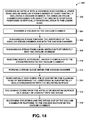
- FIG. 14 shown in FIG. 14 are one or more steps or operations that may be included in a method 300 of cleaning an article 250 .
- Step 302 of the method 300 of FIG. 14 may include covering an article 250 with a cleaning head 150 .
- FIG. 15A illustrates the lower edge 158 of the cleaning head 150 engaged to the mounting surface 254 such that the fastener 252 is enclosed within the vacuum chamber 160 .
- the steam trigger 178 may be moved to the closed position 180 to prevent steam 184 from entering the vacuum chamber 160 .
- Step 304 of the method 300 of FIG. 14 may include activating the vacuum source 118 and drawing at least a partial vacuum on the vacuum chamber 160 ( FIG. 15A ) prior to opening the steam valve 176 ( FIG. 15A ) as a means to prevent injury or damage that may otherwise occur if high temperature steam were provided to the vacuum chamber 160 without first drawing a vacuum on the vacuum chamber 160 .
- the lower edge 158 ( FIG. 15A ) of the cleaning head 150 may be placed in substantially sealing engagement with the mounting surface 254 ( FIG. 15A ) prior to opening the steam valve 176 .
- Step 306 of the method 300 of FIG. 14 may include moving the steam trigger 178 to the open position 182 as shown in FIG. 15B and allowing steam 184 to flow into the nozzle 186 and discharge through the apertures 210 into the vacuum chamber 160 .
- the steam spray 212 may be discharged from the apertures 210 at a predetermined angle which may be dictated in part by the angular orientation of the apertures 210 as described above.
- the orientation of the apertures 210 may be configured complementary to the height and geometry of the article 250 to be cleaned.
- Step 308 of the method 300 of FIG. 14 may include discharging steam spray 212 from a nozzle main outlet 188 directly into the vacuum chamber 160 .
- FIG. 15B illustrates steam spray 212 exiting the nozzle main outlet 188 along a direction generally toward the location of the article 250 and the mounting surface 254 at the lower end of the vacuum chamber 160 .
- the nozzle 186 may be configured to direct steam spray 212 from the nozzle main outlet 188 at any angle relative to the vacuum chamber 160 .
- the steam valve 176 may be manipulated to regulate the flow rate of steam 184 into the vacuum chamber 160 by using the steam trigger 178 .
- One or more temperature sensors may be included with the cleaning head 150 to sense the temperature within the vacuum chamber 160 and facilitate manual or autonomous adjustment of the temperature and/or flow rate of steam 184 into the vacuum chamber 160 to avoid overheating the article 250 .
- Step 310 of the method 300 of FIG. 14 may include injecting one or more fluids 144 ( FIG. 15B ) into the steam 184 ( FIG. 15B ) flowing toward the vacuum chamber 160 .
- the fluid 144 may comprise water, detergent, chemicals, or other compositions to expedite the cleaning process.
- Activation of the fluid injection unit 122 ( FIG. 1 ) may be achieved by moving the release switch 230 to the on position 238 as shown in FIG. 15B .
- the release switch 230 may be coupled to the release valve 126 ( FIG. 1 ) on the housing 106 ( FIG. 1 ) and may cause the injection of one or more types of fluid 144 into the steam hose 114 .
- Step 312 of the method 300 of FIG. 14 may include forming a steam cloud 214 within the vacuum chamber 160 as shown in FIG. 15B .
- the steam cloud 214 may engulf or substantially surround and contact the article 250 and the mounting surface 254 to be cleaned. In this manner, the steam cloud 214 may facilitate the removal of debris 258 ( FIG. 15A ) or contamination from one or more surfaces of the article 250 as described above.
- Step 314 of the method 300 of FIG. 14 may include maintaining the lower edge 158 of the cleaning head 150 in substantially sealed engagement with the mounting surface 254 as shown in FIG. 15B .
- the lower edge 158 is preferably configured or shaped complementary to the shape of the mounting surface(s) 254 .
- the sealing engagement of the cleaning head 150 to the mounting surface(s) 254 may substantially contain the contaminated steam, dislodged debris particles 260 , water vapor, chemicals, detergents, and other materials within the vacuum chamber 160 and prevent the release thereof into the surrounding environment.
- Step 316 of the method 300 of FIG. 14 may include the dislodgement of debris 258 ( FIG. 15A ) from the article 250 ( FIG. 15A ) or from the mounting surface 254 ( FIG. 15A ) from which the article 250 protrudes.
- the dislodgement of debris 258 may be effected by breaking the bonds between the debris 258 and the article 250 or between the debris 258 and the mounting surface 254 in a manner described above. The breaking of the bonds may result from micro-explosions that may occur when the relatively tiny hot water vapor molecules of steam 184 contact the relatively cooler debris 258 . In this manner, the debris 258 may be broken up into a plurality of relatively small debris particles 260 as shown in FIGS. 15B-15C .
- the small debris particles 260 may then become entrained in water suspension in the steam cloud 214 .
- the release switch 230 may be moved to the off position 236 ( FIG. 15A ) to halt the injection of fluid 144 into the steam hose 114 after the debris 258 is broken up into debris particles 260 .
- Step 320 of the method 300 of FIG. 14 may include vacuum suctioning 162 the debris particles 260 and the steam 184 out of the vacuum chamber 160 as shown in FIGS. 15C and 15D .
- the vacuum suctioning 162 may draw the debris particles 260 ( FIG. 15B ) into the vacuum hose 120 and ultimately into the waste receptacle 124 ( FIG. 1 ) at the housing 106 ( FIG. 1 ).
- the steam trigger 178 may be released to stop the flow of steam 184 into the vacuum chamber 160 .
- the vacuum suctioning 162 may be continued until a substantial majority of the debris particles 260 and any leftover steam 262 is drawn out of the vacuum chamber 160 .
Landscapes
- Cleaning By Liquid Or Steam (AREA)
Priority Applications (6)
| Application Number | Priority Date | Filing Date | Title |
|---|---|---|---|
| US13/283,250 US8790467B2 (en) | 2011-10-27 | 2011-10-27 | Vacuum steam cleaning apparatus and method |
| CN201280052126.2A CN103889600B (zh) | 2011-10-27 | 2012-07-18 | 真空蒸汽清洁设备和方法 |
| PCT/US2012/047152 WO2013062646A1 (en) | 2011-10-27 | 2012-07-18 | Vacuum steam cleaning apparatus and method |
| JP2014538786A JP6013495B2 (ja) | 2011-10-27 | 2012-07-18 | 真空スチーム洗浄装置及び方法 |
| EP12741195.7A EP2750810B1 (en) | 2011-10-27 | 2012-07-18 | Vacuum steam cleaning apparatus and method |
| US14/313,801 US9573170B2 (en) | 2011-10-27 | 2014-06-24 | Method of manufacturing a vacuum steam cleaning apparatus |
Applications Claiming Priority (1)
| Application Number | Priority Date | Filing Date | Title |
|---|---|---|---|
| US13/283,250 US8790467B2 (en) | 2011-10-27 | 2011-10-27 | Vacuum steam cleaning apparatus and method |
Related Child Applications (1)
| Application Number | Title | Priority Date | Filing Date |
|---|---|---|---|
| US14/313,801 Continuation US9573170B2 (en) | 2011-10-27 | 2014-06-24 | Method of manufacturing a vacuum steam cleaning apparatus |
Publications (2)
| Publication Number | Publication Date |
|---|---|
| US20130104936A1 US20130104936A1 (en) | 2013-05-02 |
| US8790467B2 true US8790467B2 (en) | 2014-07-29 |
Family
ID=46598986
Family Applications (2)
| Application Number | Title | Priority Date | Filing Date |
|---|---|---|---|
| US13/283,250 Expired - Fee Related US8790467B2 (en) | 2011-10-27 | 2011-10-27 | Vacuum steam cleaning apparatus and method |
| US14/313,801 Active 2032-08-13 US9573170B2 (en) | 2011-10-27 | 2014-06-24 | Method of manufacturing a vacuum steam cleaning apparatus |
Family Applications After (1)
| Application Number | Title | Priority Date | Filing Date |
|---|---|---|---|
| US14/313,801 Active 2032-08-13 US9573170B2 (en) | 2011-10-27 | 2014-06-24 | Method of manufacturing a vacuum steam cleaning apparatus |
Country Status (5)
| Country | Link |
|---|---|
| US (2) | US8790467B2 (zh) |
| EP (1) | EP2750810B1 (zh) |
| JP (1) | JP6013495B2 (zh) |
| CN (1) | CN103889600B (zh) |
| WO (1) | WO2013062646A1 (zh) |
Cited By (1)
| Publication number | Priority date | Publication date | Assignee | Title |
|---|---|---|---|---|
| US11174751B2 (en) | 2017-02-27 | 2021-11-16 | General Electric Company | Methods and system for cleaning gas turbine engine |
Families Citing this family (5)
| Publication number | Priority date | Publication date | Assignee | Title |
|---|---|---|---|---|
| EP2703729B1 (en) * | 2012-08-28 | 2017-12-13 | Electrolux Home Products Corporation N.V. | A cooking oven with an oven cavity and a cleaning apparatus |
| US9393579B2 (en) | 2012-10-03 | 2016-07-19 | The Boeing Company | Cleaning apparatus and method of cleaning a contaminated surface |
| US10343193B2 (en) | 2014-02-24 | 2019-07-09 | The Boeing Company | System and method for surface cleaning |
| US10688536B2 (en) | 2014-02-24 | 2020-06-23 | The Boeing Company | System and method for surface cleaning |
| US10780541B2 (en) * | 2017-09-08 | 2020-09-22 | G.A.W. Inc. | Vacuum dust extraction apparatus for a percussive air tool |
Citations (9)
| Publication number | Priority date | Publication date | Assignee | Title |
|---|---|---|---|---|
| US2497435A (en) | 1948-08-24 | 1950-02-14 | Branneman Leonard | Steam vacuum cleaner |
| US3439374A (en) | 1967-05-16 | 1969-04-22 | William H Wisdom | Steam and vacuum nozzle |
| ZA953212B (en) | 1994-04-28 | 1996-01-03 | Kentmaster Mfg Co Inc | Carcass cleaning system |
| US5502872A (en) | 1993-05-19 | 1996-04-02 | Samsung Electronics Co., Ltd. | Electric vacuum cleaner having steam discharge and cloth wiper |
| US5607349A (en) | 1994-04-28 | 1997-03-04 | Kentmaster Mfg. Co., Inc. | Carcass cleaning system |
| US5613271A (en) | 1994-10-17 | 1997-03-25 | Robert Thomas Metall- Und Elektrowerke | Vacuum cleaner |
| US6311365B1 (en) * | 1995-12-06 | 2001-11-06 | Dornier Technologies Gmbh & Co. | Steam cleaning device |
| US20030233726A1 (en) | 2002-06-19 | 2003-12-25 | Murray Christopher J. | Hand held vacuum with arcuate gliding surface |
| US8297292B2 (en) * | 2008-07-28 | 2012-10-30 | Tokyo Electron Limited | Cleaning device and cleaning method of semiconductor manufacturing apparatus |
Family Cites Families (14)
| Publication number | Priority date | Publication date | Assignee | Title |
|---|---|---|---|---|
| US3559220A (en) * | 1968-05-29 | 1971-02-02 | William H Wisdom | Portable rug dyeing machine and method |
| US3959010A (en) * | 1974-09-30 | 1976-05-25 | Thompson Tank Manufacturing Company | Vortex cleaner and method of cleaning |
| US4165993A (en) * | 1977-09-19 | 1979-08-28 | Mccarthy Carolann L | Method of flue and fireplace cleaning and apparatus used therein |
| JPH04106690A (ja) | 1990-08-27 | 1992-04-08 | Nec Corp | 乗車料金徴収システム |
| JPH04106690U (ja) * | 1991-02-26 | 1992-09-14 | 三田工業株式会社 | ドラム洗浄装置 |
| JP2001063709A (ja) * | 1999-08-26 | 2001-03-13 | Toyo Jidoki Co Ltd | 液状物の充填装置 |
| JP3673843B2 (ja) * | 2000-03-29 | 2005-07-20 | エム・テイ・システム株式会社 | エアコン洗浄方法 |
| GB0023980D0 (en) * | 2000-09-29 | 2000-11-15 | Food Pro Systems Ltd | Carcass cleaning devices and methods |
| JP3080363U (ja) * | 2001-03-16 | 2001-09-21 | 進村 程 | スチームクリーナーのスチーム制御構造 |
| DE10216685A1 (de) * | 2002-04-16 | 2003-11-06 | Nsm Magnettech Gmbh & Co Kg | Vorrichtung und Verfahren zum Reinigen von Oberflächen |
| ITPG20040015A1 (it) * | 2004-05-10 | 2004-08-10 | Fabrizio Ramaccioni | Camera di miscelazione per applicazione di un agente disinfettante tramite vapore e relativo dispositivo igienizzante |
| JP2006247110A (ja) * | 2005-03-10 | 2006-09-21 | Kanto Regional Development Bureau Ministry Of Land Infrastructure & Transport | 蒸気噴射式洗浄装置及び方法 |
| KR100530019B1 (ko) * | 2005-08-05 | 2005-11-22 | 염규설 | 용제 재생기가 장착된 세정장치 |
| CN101138763A (zh) * | 2007-09-20 | 2008-03-12 | 吴江市天地人真空炉业有限公司 | 真空复合清洗机 |
-
2011
- 2011-10-27 US US13/283,250 patent/US8790467B2/en not_active Expired - Fee Related
-
2012
- 2012-07-18 EP EP12741195.7A patent/EP2750810B1/en not_active Not-in-force
- 2012-07-18 CN CN201280052126.2A patent/CN103889600B/zh not_active Expired - Fee Related
- 2012-07-18 JP JP2014538786A patent/JP6013495B2/ja not_active Expired - Fee Related
- 2012-07-18 WO PCT/US2012/047152 patent/WO2013062646A1/en active Application Filing
-
2014
- 2014-06-24 US US14/313,801 patent/US9573170B2/en active Active
Patent Citations (9)
| Publication number | Priority date | Publication date | Assignee | Title |
|---|---|---|---|---|
| US2497435A (en) | 1948-08-24 | 1950-02-14 | Branneman Leonard | Steam vacuum cleaner |
| US3439374A (en) | 1967-05-16 | 1969-04-22 | William H Wisdom | Steam and vacuum nozzle |
| US5502872A (en) | 1993-05-19 | 1996-04-02 | Samsung Electronics Co., Ltd. | Electric vacuum cleaner having steam discharge and cloth wiper |
| ZA953212B (en) | 1994-04-28 | 1996-01-03 | Kentmaster Mfg Co Inc | Carcass cleaning system |
| US5607349A (en) | 1994-04-28 | 1997-03-04 | Kentmaster Mfg. Co., Inc. | Carcass cleaning system |
| US5613271A (en) | 1994-10-17 | 1997-03-25 | Robert Thomas Metall- Und Elektrowerke | Vacuum cleaner |
| US6311365B1 (en) * | 1995-12-06 | 2001-11-06 | Dornier Technologies Gmbh & Co. | Steam cleaning device |
| US20030233726A1 (en) | 2002-06-19 | 2003-12-25 | Murray Christopher J. | Hand held vacuum with arcuate gliding surface |
| US8297292B2 (en) * | 2008-07-28 | 2012-10-30 | Tokyo Electron Limited | Cleaning device and cleaning method of semiconductor manufacturing apparatus |
Non-Patent Citations (17)
| Title |
|---|
| "Kleenjet Ultra 5000CV Commercial / Industrial Grade steam cleaner", available at , last visited Aug. 30, 2011. |
| "Kleenjet Ultra 5000CV Commercial / Industrial Grade steam cleaner", available at <http://www.daimer.com/steam-cleaners/kleenjet-5000cv.htm>, last visited Aug. 30, 2011. |
| Daimer Industries, "Kleenjet Ultra 5000CV Commercial / Industrial Grade steam cleaner", available at , last visited Aug. 30, 2011. |
| Daimer Industries, "Kleenjet Ultra 5000CV Commercial / Industrial Grade steam cleaner", available at <http://www.daimer.com/steam-cleaners/kleenjet-5000cv.htm>, last visited Aug. 30, 2011. |
| Dupray Industries, "Carmen Super Inox Steam Cleaner", available at , last visited Aug. 30, 2011. |
| Dupray Industries, "Carmen Super Inox Steam Cleaner", available at <http://www.dupray.ca/steam-cleaning-equipment/carmen-super-inox-steam-cleaner/>, last visited Aug. 30, 2011. |
| Durr, "EcoCSteam Cleaning Process," available at , last visited Oct. 27, 2011. |
| Durr, "EcoCSteam Cleaning Process," available at <http://www.durr-ecoclean.com/products/>, last visited Oct. 27, 2011. |
| Healthgoods LLC, "Reliable Enviromate Tandem EV1 Vapor Vacuum Steam Cleaner System", available at <http://www.healthgoods.com/Reliable-Enviromate-EV1-Vapor-Vacuum-Steam-Cleaner-p/re-tandemev1.htm>, last visited Aug. 30, 2011. |
| Healthgoods LLC, "Reliable Enviromate Tandem EV1 Vapor Vacuum Steam Cleaner System", available at <http://www.healthgoods.com/Reliable—Enviromate—EV1—Vapor—Vacuum—Steam—Cleaner—p/re-tandemev1.htm>, last visited Aug. 30, 2011. |
| Helium-Where Knowledge Rules, "How steam cleaning works", available at <http://www.helium.com/items/1341724-how-a-steam-cleaner-works-steam-cleaning-step-by-step-steam-cleaning>, last visited Aug. 30, 2011. |
| Helium—Where Knowledge Rules, "How steam cleaning works", available at <http://www.helium.com/items/1341724-how-a-steam-cleaner-works-steam-cleaning-step-by-step-steam-cleaning>, last visited Aug. 30, 2011. |
| Just Renew-It, "Super Vapor 6 with Vacuum Extractor", available at , last visited Aug. 30, 2011. |
| Just Renew-It, "Super Vapor 6 with Vacuum Extractor", available at <http://refreshyourhome.com/new-steamer-windows/Vapor6-Steam-Cleaners-VAC.html>, last visited Aug. 30, 2011. |
| PCT/US2012/047152, International Search Report dated Oct. 5, 2012. |
| Wikipedia, "Vapor Steam Cleaner", available at , last visited Aug. 30, 2011. |
| Wikipedia, "Vapor Steam Cleaner", available at < http://en.wikipedia.org/wiki/Vapor—Steam—Cleaners>, last visited Aug. 30, 2011. |
Cited By (1)
| Publication number | Priority date | Publication date | Assignee | Title |
|---|---|---|---|---|
| US11174751B2 (en) | 2017-02-27 | 2021-11-16 | General Electric Company | Methods and system for cleaning gas turbine engine |
Also Published As
| Publication number | Publication date |
|---|---|
| JP6013495B2 (ja) | 2016-10-25 |
| US20140304969A1 (en) | 2014-10-16 |
| US20130104936A1 (en) | 2013-05-02 |
| EP2750810A1 (en) | 2014-07-09 |
| CN103889600A (zh) | 2014-06-25 |
| CN103889600B (zh) | 2016-01-20 |
| US9573170B2 (en) | 2017-02-21 |
| JP2014532551A (ja) | 2014-12-08 |
| WO2013062646A1 (en) | 2013-05-02 |
| EP2750810B1 (en) | 2016-05-18 |
Similar Documents
| Publication | Publication Date | Title |
|---|---|---|
| US9573170B2 (en) | Method of manufacturing a vacuum steam cleaning apparatus | |
| US11351579B2 (en) | System and method for surface cleaning | |
| US11167325B2 (en) | Method for surface cleaning | |
| CN103621489B (zh) | 用于害虫控制和清洁的干蒸汽处理装置 | |
| JP2015518415A (ja) | 塗装設備用ドライアイス洗浄手段 | |
| KR101697458B1 (ko) | 에어 실리콘건 | |
| JP6328944B2 (ja) | ドライアイスブラスト装置 | |
| EP2819791B1 (en) | Vacuum assisted containment cleaning | |
| KR102117705B1 (ko) | 원터치 고압분사노즐장치 | |
| JP2006239633A (ja) | ストレーナ洗浄装置 | |
| JP2021094556A (ja) | 容器洗浄用装置及び方法 | |
| KR101464068B1 (ko) | 드라이아이스를 이용한 에어컨세척기 | |
| TWM479799U (zh) | 用於清洗噴槍的清洗裝置 | |
| JP2010253399A (ja) | 汚染表面清掃方法 | |
| EP3814026B1 (en) | Cleaning system and method for graffiti removal | |
| KR20230073459A (ko) | 다용도 이동식 청소 및 소독 장치 |
Legal Events
| Date | Code | Title | Description |
|---|---|---|---|
| AS | Assignment |
Owner name: THE BOEING COMPANY, ILLINOIS Free format text: ASSIGNMENT OF ASSIGNORS INTEREST;ASSIGNOR:PONOMAREV, SERGEY G.;REEL/FRAME:027135/0032 Effective date: 20111027 |
|
| STCF | Information on status: patent grant |
Free format text: PATENTED CASE |
|
| MAFP | Maintenance fee payment |
Free format text: PAYMENT OF MAINTENANCE FEE, 4TH YEAR, LARGE ENTITY (ORIGINAL EVENT CODE: M1551) Year of fee payment: 4 |
|
| FEPP | Fee payment procedure |
Free format text: MAINTENANCE FEE REMINDER MAILED (ORIGINAL EVENT CODE: REM.); ENTITY STATUS OF PATENT OWNER: LARGE ENTITY |
|
| LAPS | Lapse for failure to pay maintenance fees |
Free format text: PATENT EXPIRED FOR FAILURE TO PAY MAINTENANCE FEES (ORIGINAL EVENT CODE: EXP.); ENTITY STATUS OF PATENT OWNER: LARGE ENTITY |
|
| STCH | Information on status: patent discontinuation |
Free format text: PATENT EXPIRED DUE TO NONPAYMENT OF MAINTENANCE FEES UNDER 37 CFR 1.362 |
|
| FP | Lapsed due to failure to pay maintenance fee |
Effective date: 20220729 |