US8704076B2 - Thermoelectric tempering device - Google Patents
Thermoelectric tempering device Download PDFInfo
- Publication number
- US8704076B2 US8704076B2 US12/450,825 US45082508A US8704076B2 US 8704076 B2 US8704076 B2 US 8704076B2 US 45082508 A US45082508 A US 45082508A US 8704076 B2 US8704076 B2 US 8704076B2
- Authority
- US
- United States
- Prior art keywords
- tempering
- recited
- fans
- elements
- housing
- Prior art date
- Legal status (The legal status is an assumption and is not a legal conclusion. Google has not performed a legal analysis and makes no representation as to the accuracy of the status listed.)
- Expired - Fee Related, expires
Links
Images


Classifications
-
- H01L35/32—
-
- H—ELECTRICITY
- H10—SEMICONDUCTOR DEVICES; ELECTRIC SOLID-STATE DEVICES NOT OTHERWISE PROVIDED FOR
- H10N—ELECTRIC SOLID-STATE DEVICES NOT OTHERWISE PROVIDED FOR
- H10N10/00—Thermoelectric devices comprising a junction of dissimilar materials, i.e. devices exhibiting Seebeck or Peltier effects
- H10N10/10—Thermoelectric devices comprising a junction of dissimilar materials, i.e. devices exhibiting Seebeck or Peltier effects operating with only the Peltier or Seebeck effects
- H10N10/17—Thermoelectric devices comprising a junction of dissimilar materials, i.e. devices exhibiting Seebeck or Peltier effects operating with only the Peltier or Seebeck effects characterised by the structure or configuration of the cell or thermocouple forming the device
-
- F—MECHANICAL ENGINEERING; LIGHTING; HEATING; WEAPONS; BLASTING
- F24—HEATING; RANGES; VENTILATING
- F24F—AIR-CONDITIONING; AIR-HUMIDIFICATION; VENTILATION; USE OF AIR CURRENTS FOR SCREENING
- F24F5/00—Air-conditioning systems or apparatus not covered by F24F1/00 or F24F3/00, e.g. using solar heat or combined with household units such as an oven or water heater
- F24F5/0042—Air-conditioning systems or apparatus not covered by F24F1/00 or F24F3/00, e.g. using solar heat or combined with household units such as an oven or water heater characterised by the application of thermo-electric units or the Peltier effect
-
- H—ELECTRICITY
- H05—ELECTRIC TECHNIQUES NOT OTHERWISE PROVIDED FOR
- H05K—PRINTED CIRCUITS; CASINGS OR CONSTRUCTIONAL DETAILS OF ELECTRIC APPARATUS; MANUFACTURE OF ASSEMBLAGES OF ELECTRICAL COMPONENTS
- H05K7/00—Constructional details common to different types of electric apparatus
- H05K7/20—Modifications to facilitate cooling, ventilating, or heating
- H05K7/20536—Modifications to facilitate cooling, ventilating, or heating for racks or cabinets of standardised dimensions, e.g. electronic racks for aircraft or telecommunication equipment
- H05K7/206—Air circulating in closed loop within cabinets wherein heat is removed through air-to-air heat-exchanger
-
- F—MECHANICAL ENGINEERING; LIGHTING; HEATING; WEAPONS; BLASTING
- F24—HEATING; RANGES; VENTILATING
- F24F—AIR-CONDITIONING; AIR-HUMIDIFICATION; VENTILATION; USE OF AIR CURRENTS FOR SCREENING
- F24F2221/00—Details or features not otherwise provided for
- F24F2221/36—Modules, e.g. for an easy mounting or transport
-
- F—MECHANICAL ENGINEERING; LIGHTING; HEATING; WEAPONS; BLASTING
- F28—HEAT EXCHANGE IN GENERAL
- F28F—DETAILS OF HEAT-EXCHANGE AND HEAT-TRANSFER APPARATUS, OF GENERAL APPLICATION
- F28F2210/00—Heat exchange conduits
- F28F2210/08—Assemblies of conduits having different features
Definitions
- thermoelectric tempering device having a plurality of thermoelectrically operating tempering elements, one side of which includes a cold surface that forms upon the supply of an electric current while an opposite side comprises a hot surface, and air/heat exchange elements are affixed to both sides, each accommodated in a respective air flow chamber, and ventilators produce an air flow along these air/heat exchange elements.
- a tempering device is disclosed in German Patent Reference DE 200 07 920 U1, in connection with a ventilating device for a housing, for example an electrical cabinet containing electronic equipment.
- This known ventilating device embodied as a roof unit is laid out as a flat, block-shaped unit equipped with a plurality of air flow chambers and among other things, has a heat exchange unit with at least one Peltier element that can cool or heat air flowing past one surface, depending on the selected flow direction of the electric current, while the other surface is conversely cooled or heated.
- This actively functioning Peltier heat exchange unit is preceded by a separate flow chamber with a heat exchanger in the flow path, which is preceded by a radial fan for supplying an internal air flow.
- the internal air flow crosses an external air flow in order to exchange heat before the air then travels to the Peltier heat exchange unit, on the one hand, being subsequently vented to the surroundings by an axial fan and on the other hand, being conveyed in the form of tempered air into the electrical cabinet.
- the Peltier heat exchange unit functions in an auxiliary fashion together with other tempering components of the ventilating device, in particular the preceding heat exchanger.
- the overall ventilating device, together with the air flow chambers forms a relatively bulky unit.
- thermoelectric tempering device equipped with Peltier elements and disclosed in the previously unpublished German Patent Reference 10 2006 020 499.9
- an increase in the efficiency is achieved in a flat, compact design because a flow conduit feeds into a multitude of partial flow conduits that lead to the heat exchanger elements in order to produce a heat transfer with air flowing through.
- U.S. Patent Reference US 2006/0137359 A1 discloses a thermoelectric tempering device for cooling or heating, equipped with a plurality of Peltier element modules. Closed circuits filled with a heat transmitting fluid, such as liquid metal, are routed over the cold and hot surfaces. A heat exchanger can also be situated in the circuits. A fan unit with suitable cooling conduits is not provided in this design.
- German Patent Reference DE 102 18 343 B4 discloses an electric tempering device equipped with Peltier elements for motor vehicles. In this case, only the one side of the Peltier elements is exposed to an air flow produced in a surrounding conduit. This air flow is conveyed into the interior of the vehicle while the other cool side is in thermal contact with power components of the drive unit. Consequently, no corresponding cooling conduit and relevant fan unit are provided on the second side.
- Japanese JP 2000130909 A discloses another thermoelectric tempering device equipped with Peltier elements for cooling or heating.
- fans are provided that can be driven at different power levels.
- these are situated on the outside of a housing on a Peltier unit and are oriented perpendicular to its surface.
- U.S. Pat. No. 6,181,556 B1 discloses another thermoelectric tempering device equipped with a plurality of thermoelectrically functioning tempering elements.
- a plurality of Peltier elements are connected to heat sinks that have fins on only one side and have fans mounted on them in order to cool a processor unit CPU or another semiconductor element, which is mounted on a circuit board and is brought into connection with the cooling device in a particular way or is enclosed by the latter.
- a thermally coupled bridge is also provided for the cooling. It is difficult to achieve a definite air flow with this design.
- German Patent Reference DE 200 13 775 U1 discloses a thermoelectric tempering device, a cooling unit equipped with Peltier elements.
- chambers equipped with fans are situated on the hot side and the cold side of the Peltier element.
- a heat sink is provided, which dissipates the produced heat to the surrounding air and between the cold side and the relevant fan, another heat sink is provided, which is equipped with fins in order, together with the fan, to distribute the cooling action from the heat sink into the unit to be cooled.
- thermoelectric tempering device of the type mentioned above but that users can employ for various purposes with as little difficulty as possible, in particular for cooling electrical cabinets or housings.
- thermoelectric tempering device having characteristics taught in this specification and in the claims.
- the air flow chambers are formed as flow conduits that encompass the heat exchange elements laterally in the flow direction at their end remote from the tempering elements and have an air inlet opening and an air outlet opening, with the fan of the respective flow conduit being situated at its respective inlet opening or outlet opening.
- the space-saving, compact design provides advantageous installation possibilities in an electrical cabinet containing built-in electronic components or also in smaller housings.
- Other uses are also possible, for example a cooling of surfaces or substances of various types.
- a high efficiency and a low weight are achieved in comparison to conventionally designed devices.
- the tempering can comprise a cooling or heating of the air conveyed past, depending on the selected electric current direction of the relevant tempering elements.
- Various embodiments of the design have fans integrated into the side of the unit, next to the relevant heat exchange element, both on the same side of the tempering module or on opposite sides of it.
- each respective fan is embodied as an axial fan and the respective flow conduit, in its region oriented toward the relevant axial fan, has a directional component oriented in the axial direction of the radial fan.
- both fans are embodied as blowing fans, both fans are embodied as suction fans, or one fan is embodied as a suction fan while the other fan is embodied as a blowing fan.
- a design that is advantageous in terms of a maximum possible efficiency is achieved if the heat exchange elements are equipped with fins oriented perpendicular to the cold surface or the hot surface and parallel to the flow of air through the relevant flow conduit.
- the tempering capacity such as for an electrical cabinet or larger housing containing electrical equipment that generates a high amount of thermal dissipation loss, can be advantageously increased in that a unit, which is embodied as a tempering module and is part of the tempering device, has a coupling device situated in at least one edge section in the vicinity of the circumference edge, by which it is possible to attach a correspondingly embodied additional tempering module equipped with a complementary coupling device.
- a reliable coupling is achieved if each tempering module has a coupling device in one edge section and a complementary coupling device in another edge section.
- each tempering module has a coupling device in one edge section and a complementary coupling device in another edge section.
- the outer contour of the tempering module can be different, but it is advantageous for it to be rectangular or square viewed from above so that, for example with a coupling device and complementary coupling device situated in the narrow edge sections on opposite sides of a tempering module, simple expansion options are achieved by attaching additional tempering modules in sequence, thus achieving a cascading and scaling of the tempering capacity.
- the mechanical coupling components or means have plug connection elements, detent connection elements, screw connection elements, and/or magnetic connection elements.
- a control unit with a control module which is electrically connected or connectable to a tempering module or a group of them and is embodied so that it is possible to control or regulate a tempering module and/or a plurality of tempering modules in connection with different levels of tempering capacity.
- control unit is embodied so that it is possible to control or regulate different tempering capacities by driving the fans at different speeds and/or by varying the control of the power supply to the tempering elements.
- control unit is able to control the tempering modules differently from one another.
- control unit is embodied so that it is able to drive the fans with different levels of electrical power and to drive the tempering elements with different levels of electrical power in order to meet various tempering capacity requirements and by the fact that the driving of the fans and the driving of the tempering elements are matched to each other so as to minimize the total electrical power demand for driving the fans and tempering elements at the respective tempering capacity.
- control unit has at least one controller embodied as a microcontroller, which has programs stored on it for producing signals for driving the fans and tempering elements as a function of sensor signals that communicate the tempering capacity requirement.
- an electric power supply with at least one power supply module is provided, which each is embodied for supplying power selectively to a single tempering module or to a group of tempering modules.
- control unit has at least one control module with its own housing and the control module and/or each power supply module has a coupling device for electrically and/or mechanically coupling to one more tempering modules.
- a design that is advantageous for the function and use has a tempering module having a housing with a housing bottom part and a housing top part and the tempering elements, heat exchange elements, and fans are situated and secured in the housing bottom part.
- the flow conduits are situated in the housing bottom part.
- the housing bottom part is block-shaped and has a detachably mounted housing bottom on its underside and is covered on its opposite surface by the housing top part.
- the housing bottom contains an inlet opening and an outlet opening flow-connected to it via a flow conduit possibly including a plurality of branch conduits.
- the housing top part contains another inlet opening and another outlet opening flow-connected to it via another flow conduit possibly including a plurality of branch conduits.
- a compact design with a favorable degree of manageability is facilitated if the housing top part protrudes outward like a dome on top and in its longitudinal section, is trapezoidal or arched convexly outward and a receiving chamber is formed between a middle section of the housing top part and an intermediate wall in the upper region of the housing bottom part oriented toward the top housing part.
- An electric power supply, in particular a power pack, is accommodated in this receiving chamber.
- the production is facilitated if a housing insert with block-shaped outer contours is inserted into the housing bottom part and the flow conduits are embodied in the housing insert.
- the housing insert can be manufactured, for example, of a heat-resistant, stable plastic material.
- a compact design with a favorable degree of manageability is also facilitated if the housing insert is shortened in its longitudinal direction in comparison to the housing bottom part and if the controller is accommodated in the space between a narrow outside of the housing insert and the narrow inside of the housing bottom part oriented toward it.
- FIG. 1 is a schematically depicted longitudinal section taken through a tempering module installed in an electrical cabinet wall;
- FIG. 2 is a perspective view of a tempering module according to FIG. 1 ;
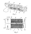
- FIG. 3 is a schematically depicted longitudinal section taken through another exemplary embodiment for a tempering module
- FIG. 4 is a schematically depicted longitudinal section taken through another exemplary embodiment for a tempering module installed in an electrical cabinet wall;
- FIG. 5 is a perspective view of the tempering module according to FIG. 4 ;
- FIG. 6 is a schematic view of a plurality of tempering modules to be combined into a unit
- FIG. 7 is a schematic top view of a plurality of tempering modules to be combined into a unit, as well as electrical supply modules to be associated with it;
- FIG. 8 is a schematic view of a plurality of tempering modules that can be combined into a unit, as well as a control module and an electrical supply module;
- FIG. 9 is a schematic view of a plurality of tempering modules to be combined into a unit, equipped with a coupling device;
- FIG. 10 is a schematically depicted longitudinal section taken through another embodiment of a tempering module, mounted on a housing wall;
- FIG. 11 is a perspective view of a longitudinal section taken through another embodiment of a tempering module according to FIG. 10 ;
- FIGS. 12A and 12B are perspective top and bottom views of the tempering module according to FIG. 11 ;
- FIGS. 13A through 13G show various views of the tempering module according to FIG. 11 , namely a top view, a longitudinal section, a view from the right, two cross-sectional views taken along the intersecting planes B-B and C-C, and a side view;
- FIG. 14 is an exploded perspective view of the tempering module according to FIG. 11 ;
- FIG. 15 is a perspective view of the tempering module in a state in which it is mounted on a housing;
- FIG. 16 shows the housing according to FIG. 15 with the mounted tempering module, looking into an interior of the housing with the door open;
- FIG. 17 is a perspective view of a tempering module installed in a housing that is complete except for a top part
- FIG. 18 is a schematic block circuit diagram of a control unit for the tempering device.
- FIG. 1 shows a tempering module 1 of a thermoelectric tempering device, built into a rear wall 2 . 1 of an electrical cabinet 2 .
- a part of the tempering module 1 is positioned or situated within the interior 2 . 3 of the electrical cabinet 2 delimited laterally by the side walls 2 . 2 while the other part is positioned or situated on the exterior 2 . 4 of the electrical cabinet 2 .
- the part of the tempering module 1 oriented toward the interior 2 . 3 tempers the interior air of the electrical cabinet 2 in order, for example, to cool the interior air heated by the lost heat from electrical components and to maintain a particular temperature level. If the interior temperature is too low, the tempering module 1 can also be used to heat the interior air by reversing the flow direction. Similar built-in components of the tempering module 1 can also be provided in smaller interiors, such as in housings, and it is also possible for the tempering module 1 to be used in connection with surfaces to be cooled or materials of other kinds.
- the tempering module 1 preferably has a plurality of thermoelectric elements, in particular Peltier elements 10 , which, in an intrinsically known fashion, generate cold on one flat side and heat on an other flat side when an electric current flows through them.
- the cold side and hot side can be reversed by reversing the flow direction.
- the cold surface and hot surface of the tempering elements 10 have heat exchange elements 11 and 11 ′ mounted to them, with fins extending perpendicular to the respective surface.
- these fins are shown or depicted perpendicular to the plane of the drawing in FIG. 1 , and also in FIGS. 3 , 4 , and 6 , but actually, they extend parallel to the flow direction, indicated by the arrows, of the air conveyed through the heat exchange elements 11 and 11 ′.
- the exchange element 11 , 11 ′ produces a heat exchange between the relevant surfaces of the tempering elements 10 with a high degree of efficiency, particularly if the heat exchange element 11 , 11 ′ is composed of or comprises a material with a good thermal conductivity such as aluminum or copper.
- the flow conduit extends parallel to the cold or hot surface of the tempering elements 10 and at the one end, has an air inlet opening 14 , 14 ′ in a plane oriented vertically in relation to the cold or hot surface of the tempering elements 10 and perpendicular to the flow direction and at its opposite end 14 , 14 ′, has an air outlet opening 16 , 16 ′.
- a respective fan 13 , 13 ′ is provided, which blows air through the respective flow conduit 15 , 15 ′ with the heat exchanger 11 , 11 ′ and this air, after flowing out through the air outlet opening 16 , 16 ′, at one end, flows out in a tempered state into the interior 2 .
- the fans 13 , 13 ′ are embodied as radial fans that draw the air in axially and blow it into the flow conduit 15 , 15 ′ through a radial opening with which they are connected to the flow conduit in a sealed fashion. In this way, the air to be tempered in the interior 2 . 3 of the electrical cabinet 2 is brought to the required temperature with a high degree of efficiency.
- This design also yields a compact, relatively flat structure.
- the fans 13 , 13 ′ are each coupled to the flow conduit 15 , 15 ′ by a respective conduit section 17 , 17 ′. Similar conduit sections are also provided at the air outlet opening 16 , 16 ′. The conduit sections at the outlet end can convey the air perpendicular, for example, to the flow direction prevailing in the flow conduit 15 , 15 ′, as is also the case at the inlet end, where the air enters into the relevant fan 13 , 13 ′ perpendicular to the flow direction in the conduit.
- the fan associated with the cold surface of the tempering elements 10 on the one hand and the fan associated with their hot surface on the other hand are situated at opposite ends of the flow conduit 15 , 15 ′ and, because of the blowing embodiment of the fans 13 , 13 ′, the flow direction is oriented in opposite directions in the two heat exchange elements 11 , 11 ′, as indicated by the flow arrows.
- a counterflow principle of this kind is also used in the exemplary embodiment of the tempering module 1 shown in FIG. 3 .
- the one fan in this case the fan associated with the interior of the electrical cabinet, is embodied as a blowing radial fan while the other fan, in this case the fan 13 ′ associated with the exterior 2 . 4 , is embodied as a suction radial fan.
- the air is drawn through the radial opening of the fan, through the air inlet opening 14 ′, the flow conduit 15 ′, and the air outlet opening 16 ′ and is conveyed axially outward by the fan 13 ′.
- the two fans 13 , 13 ′ of the respective cold and hot surfaces of the tempering elements 10 are likewise connected to the same end of the tempering module 1 , each to its respective flow conduit 15 , 15 ′.
- the two fans 13 , 13 ′ are again embodied as blowing fans, preferably radial fans, thus producing a design of the tempering module 1 that functions in accordance with the parallel flow principle, as indicated by the flow arrows in FIG. 4 .
- This produces a more compact design than in the exemplary embodiment according to FIG. 1 because of the arrangement of the blowing fans at the same end of the tempering module 1 , but as a rule, a lower level of efficiency is achieved than with the counterflow principle in which a more constant temperature distribution prevails over the entire cross-section.
- FIG. 6 shows the possibility of combining a plurality of tempering modules 1 .
- the fans 13 , 13 ′ are positioned or situated, for example, at one end of the combined unit composed of a plurality of tempering modules 1 and produce a flow through the tempering modules 1 that are arranged in series with one another in the flow direction.
- the conduit sections 17 , 17 ′ of the adjoining tempering modules 1 can be removed.
- blowing fans can be situated at one end of the conduit and suction fans can be situated at the other end of the same conduit.
- a coupling device 20 , 20 ′ with mechanical coupling or coupling means 21 , 21 ′ and/or electrical coupling components 22 , 23 is provided at the associated ends of the tempering modules 1 .
- the mechanical coupling means 21 and electrical coupling components 22 on the one tempering module 1 are embodied to complement the mechanical coupling means 21 ′ and electrical coupling components 23 on the other tempering module 1 .
- the coupling device 20 , 20 ′ can advantageously be mounted on a supporting section or a section of a frame 25 , 25 ′, as shown in FIG. 9 .
- the fans 13 , 13 ′ of the tempering modules 1 remain attached to them and are situated next to one another.
- the sequential arrangement of the tempering modules there are many possibilities for adapting to different requirements of the tempering capacity, and there are possibilities for subsequent expansion, for example when requirements change due to the installation or replacement of components to be cooled.
- the tempering device can also be equipped with one or more power packs that can be easily connected in the form of electric power supply modules 30 , 30 ′ to a tempering module 1 or to a group of tempering modules 1 , as shown in FIG. 7 .
- the power supply modules 30 , 30 ′ are advantageously provided with a coupling device 20 , 20 ′ for a mechanical and/or electrical coupling, as described above in connection with the coupling of tempering modules 1 and schematically depicted in FIG. 8 .
- a control unit 40 is provided to control or regulate the tempering and advantageously has at least one control module that is embodied for controlling a varying number of tempering modules 1 and is also able to control only one tempering element, for example, and can also have a monitoring device for this purpose.
- the control modules have programmable microcontrollers and can also have AC/DC converters and other necessary electrical control components.
- the control unit 40 in this case can control or regulate the tempering capacity, such as by driving the fans 13 , 13 ′ at different speeds and/or by supplying current to the tempering elements until they switch on or switch off. It is thus possible to achieve an extensive, selective control or regulation of the tempering.
- FIG. 9 shows several mechanical coupling means 21 , 21 ′, such as a screw connection, a snap hook, or a magnetic connection having magnet elements situated on the two tempering modules 1 to be joined to each other, on the power supply module 30 , 30 ′, or on the control module 40 .
- a screwless detent connection is also possible.
- the electrical coupling components 22 , 23 can be embodied as plug/coupling units. It is also possible to provide a frame 25 that includes a plurality of interconnected tempering modules 1 , possibly combined with a power supply module 30 , 30 ′ and/or a control module 40 .
- FIG. 10 is a schematic, longitudinal section taken through another exemplary embodiment of the tempering device, with a tempering module 1 mounted externally to a housing wall, such as a back wall 2 . 1 .
- a thermoelectric element arrangement is situated, for example equipped with at least one Peltier element 10 whose one side, such as a cold side, is oriented toward the back wall 2 . 1 and whose other side, such as a hot side, is oriented away from the back wall 2 . 1 .
- the back wall 2 .
- the tempering module 1 has openings that are positioned so as to correspond to the air inlet opening 14 and the air outlet opening 16 of the tempering module 1 or has a single large opening for them both, through which the air flowing along the Peltier element 10 is conveyed from the interior of the housing 2 and then once cooled, is conveyed back into the housing as indicated by the air flow L, which is produced by the fan 13 situated in the vicinity of the air outlet opening 16 .
- the heat exchangers on the two sides of the Peltier elements 10 through which the air flows L pass have been omitted from the drawing for the sake of better visibility. Also, the air flow L conveyed along the side of the Peltier element 10 oriented away from the back wall 2 .
- the air inlet opening 14 ′ and the air outlet opening 16 ′ are embodied in both end regions of a housing top part 7 that protrudes upward toward the outside.
- the middle region of the housing top part that arches up away from the back wall 2 . 1 covers an intermediate space that is embodied between an intermediate wall 8 in the upper region of the housing bottom part 6 and the inside of the housing top part 7 and accommodates a power pack 42 of a power supply.
- the space between the intermediate wall 8 and the covering wall of the housing top part 7 contains optical indicators 43 , such as light-emitting diodes or controllable alphanumeric characters.
- a receiving space is provided in which a controller 41 equipped with a microcontroller is accommodated. This receiving space for the controller 41 of the control unit 40 is formed between a housing insert 9 , shown more clearly in FIG. 14 , and the inside of the narrow side wall of the housing bottom part 6 .
- FIGS. 11 through 14 The embodiment of a tempering module schematically depicted in FIG. 10 is shown in greater detail in FIGS. 11 through 14 .
- the cooling conduits 15 , 15 ′ are embodied in the housing insert 9 in the form of curved conduits that have partially constricted and partially expanded flow cross-sections so that the air flowing past the Peltier elements 10 , in particular past the highly thermally conductive fin-heat exchanger elements 11 , 11 ′ attached to them, flows without hindrance and is tempered with a high degree of efficiency.
- the Peltier elements 10 are situated in one or more planes extending parallel to the side walls of the housing bottom part 6 .
- the fins protrude from the hot side of the Peltier elements 10 on the one hand and from their cold side on the other, extending perpendicular to the side walls of the housing bottom part 6 and thus parallel to the bottom 28 of the housing bottom part 6 .
- the intermediate walls of the cooling conduits 15 , 15 ′ which are likewise oriented parallel to the sides of the housing bottom part 6 , are positioned in the region of or near the Peltier elements 10 and in the same plane as them so that a layered structure of cooling conduits is produced in the region of or near the Peltier elements 10 , with conduit layers situated parallel to the side walls of the housing bottom part 6 , as shown in FIG. 11 .
- the Peltier elements can be spread out essentially over the entire height of the housing bottom part 6 and of the housing insert 9 inserted into it, in the region of or near the central transverse plane in the longitudinal direction of the module housing 5 .
- Peltier elements 10 that are spaced apart from one another in parallel fashion in relation to the side walls of the housing bottom part 6 are arranged with physically equal sides oriented toward each other, such as hot/hot or cold/cold, so that the intermediate space between two parallel, spaced-apart Peltier elements 10 yields the associated conduit width.
- the fins of the heat exchange elements 11 , 11 ′, which are mounted to the sides of the Peltier elements 10 that face toward each other, with their free ends oriented toward one another, are situated as close to one another as possible in order to have the most effective possible heat exchange with the air passing through.
- This layered structure of the flow conduits 15 , 15 ′ only needs to be present in the region of or near the Peltier elements 10 with the heat exchange elements 11 , 11 ′, while the flow conduits 15 , 15 ′ in the region of or near the air inlet openings 14 , 14 ′ and air outlet openings 16 , 16 ′ can extend over the entire width of the housing bottom part 6 or of the housing insert 9 inserted into it and the flow conduits 15 , 15 ′ associated with the cold side, such as leading to the electrical cabinet interior, and the hot side, such as leading to the outside, are embodied with wall sections extending perpendicular to the side walls of the housing bottom part 6 .
- FIG. 11 also shows the fans 13 , 13 ′ that are situated in the vicinity of or near the air outlet openings 16 , 16 ′ and that in this exemplary embodiment, are embodied in the form of axial fans.
- the fan 13 ′ associated with the flow conduit 15 ′ leading outward is oriented with the fan axis inclined in relation to the narrow longitudinal side of the block-shaped module housing 5 and is accommodated in a correspondingly formed recess of the housing insert 9 and fixed in place therein by a detent engagement, for example.
- the orientation of the fan axis inclined in relation to the narrow side wall, and parallel to the long side walls, matches the direction of the air flow conduit 15 ′ in this region so that at least a significant component of the flow conduit is oriented in the direction of the fan axis and a flow of air is achieved that is as uniform as possible and largely unhindered, with a high air flow rate at a fan power that is as low as possible, thus minimizing the energy demand for the driving of the fan and at the same time, also producing the least possible amount of noise.
- the section extending perpendicular to the side walls of the housing bottom part is also inclined at an angle in relation to the narrow side wall of the module housing and is inclined at approximately the same angle as the fan axis.
- the air-inlet section of the flow conduit 15 ′ is also oriented toward the inlet opening 14 ′ in a corresponding fashion.
- the flow conduit 15 connected to the interior of the housing or electrical cabinet is also formed in a similar way, but the relationship to the interior of the electrical cabinet 2 or housing is taken into account. In this case, however, because of the flat bottom side of the housing bottom part 6 and housing insert 9 , the fan situated in the vicinity of or near the air outlet opening 16 of the flow conduit 15 is arranged with its axis perpendicular to the bottom 28 of the housing bottom part 6 for installation reasons.
- the air inlet openings 14 , 14 ′ and air outlet openings 16 , 16 ′ have respective ventilation grilles 27 in order to prevent larger foreign objects from entering the flow path.
- the ventilation grilles 27 can be arranged in combination with fan filter pads in separately removable, detent-engaged inserts 26 so that they can be easily replaced.
- the housing top part 7 which is essentially trapezoidal in its longitudinal section or alternatively is arched convexly outward, has inserts 26 at the two lateral end regions forming the inclined lateral surfaces in the trapezoidal shape, which also contain the relevant air inlet opening 14 ′ or air outlet opening 16 ′, respectively, optionally provided with the associated fan 13 ′.
- FIG. 14 The design of the module housing 5 with the housing bottom part 6 , housing top part 7 , and housing insert 9 with the associated fans 13 , 13 ′ is shown in detail in FIG. 14 , which also shows the insertion of the fans 13 , 13 ′, the air inlet openings 14 , 14 ′, and air outlet openings 16 , 16 ′, with the respective ventilation grilles 27 and optionally, fan filter pads 27 . 1 and the inserts 26 of the housing top part 7 .
- the drawing also shows the arrangement of the flow conduits 15 , 15 ′ provided in the housing insert 9 , which are layered in relation to the side wall of the housing bottom part 6 , with the flow conduit 15 situated in the middle in the transverse direction and two sections of the flow conduit 15 ′, corresponding to the associated outside of the Peltier elements 10 , situated in the regions adjoining the sides.
- sealing elements are situated between the essential components of the housing bottom part 6 and the housing top part 7 .
- the housing insert 9 can be manufactured out of heat-resistant plastic while the housing bottom part 6 is manufactured out of metal, for example, and the housing top part 9 is likewise manufactured out of plastic.
- the housing bottom part 6 has a lower section with a U-shaped cross-section, with a bottom 28 and side walls, while an upper section of the housing bottom part 6 has the intermediate wall 8 with corresponding openings for the air inlet opening 14 ′ and air outlet opening 16 ′ as well as two narrow side walls of the block-shaped housing bottom part 6 .
- a tempering module 1 can be mounted with its bottom 28 directly against the outside, such as back wall 2 . 1 of the housing 2 , with openings provided in the back wall 2 . 1 that correspond to the air inlet opening 14 and air outlet opening 16 .
- the entire interior of the housing 2 is largely available for built-in equipment, as also shown in FIG. 16 .
- the tempering module 1 is inserted, except for the housing top part 7 , from the outside into the interior of the housing 2 , into a correspondingly embodied opening in the back wall 2 . 1 . Consequently, the tempering devices according to the exemplary embodiments shown in FIGS. 10 through 17 are also suitable for mounting on or installing in housings or electrical cabinets. In this case, a plurality of such fan units can be arranged parallel to one another, with their longitudinal sides next one another, in order to achieve various tempering capacities.
- FIG. 18 shows an exemplary embodiment for the control unit 40 of a tempering module 1 or a combination of a plurality of tempering modules.
- the control unit can, for example, have a controller embodied in the above-described fashion, situated between the inside of the housing top part 7 and the top side of the intermediate wall 8 and/or a controller 41 or situated between the narrow side of the housing insert 9 and the narrow side of the housing bottom part 6 .
- the controller 41 can have a programmable microcontroller.
- the microcontroller has a program stored in it for controlling the tempering module 1 through the way in which it drives the fans 13 , 13 ′ and Peltier elements 10 .
- the supply of electrical energy to the fans 13 , 13 ′ and Peltier elements 10 is preferably carried out by the power pack 42 that is situated in the receiving space between the housing top part 7 and the intermediate wall 8 .
- a particular supply voltage is predetermined, such as 24V, while the required tempering capacity, cooling capacity, or heating capacity is likewise controlled or regulated in the most energy-efficient way possible as a function of environmental parameters and sensor signals through optimized driving of the Peltier elements 10 and fans 13 , 13 ′.
- the drive characteristics of the fans 13 , 13 ′ and Peltier elements 10 are set into relation with each other in the controller and an energy-optimized driving of these elements is selected.
- the Peltier elements 10 permit a maximum temperature difference between the hot side and the cold side in a particular current/drive range and the fans are designed so that the volume flow rate of the fans reaches an optimum as a function of the electrical current, adapted to the characteristic curve of the Peltier elements and the adapted geometry of the flow conduits.
Landscapes
- Engineering & Computer Science (AREA)
- General Engineering & Computer Science (AREA)
- Chemical & Material Sciences (AREA)
- Sustainable Development (AREA)
- Combustion & Propulsion (AREA)
- Mechanical Engineering (AREA)
- Life Sciences & Earth Sciences (AREA)
- Aviation & Aerospace Engineering (AREA)
- Physics & Mathematics (AREA)
- Thermal Sciences (AREA)
- Microelectronics & Electronic Packaging (AREA)
- Cooling Or The Like Of Electrical Apparatus (AREA)
- Devices For Blowing Cold Air, Devices For Blowing Warm Air, And Means For Preventing Water Condensation In Air Conditioning Units (AREA)
- Control Of Temperature (AREA)
Applications Claiming Priority (4)
| Application Number | Priority Date | Filing Date | Title |
|---|---|---|---|
| DE202007018397U | 2007-04-12 | ||
| DE202007018397U DE202007018397U1 (de) | 2007-04-12 | 2007-04-12 | Thermoelektrische Temperiervorrichtung |
| DE202007018397.6 | 2007-04-12 | ||
| PCT/EP2008/002890 WO2008125301A2 (de) | 2007-04-12 | 2008-04-11 | Thermoelektrische temperiervorrichtung |
Publications (2)
| Publication Number | Publication Date |
|---|---|
| US20110017252A1 US20110017252A1 (en) | 2011-01-27 |
| US8704076B2 true US8704076B2 (en) | 2014-04-22 |
Family
ID=39864796
Family Applications (1)
| Application Number | Title | Priority Date | Filing Date |
|---|---|---|---|
| US12/450,825 Expired - Fee Related US8704076B2 (en) | 2007-04-12 | 2008-04-11 | Thermoelectric tempering device |
Country Status (7)
| Country | Link |
|---|---|
| US (1) | US8704076B2 (zh) |
| EP (1) | EP2147584B1 (zh) |
| JP (1) | JP5274544B2 (zh) |
| CN (1) | CN101675718B (zh) |
| DE (1) | DE202007018397U1 (zh) |
| RU (1) | RU2465750C2 (zh) |
| WO (1) | WO2008125301A2 (zh) |
Cited By (3)
| Publication number | Priority date | Publication date | Assignee | Title |
|---|---|---|---|---|
| US9360240B2 (en) | 2012-11-09 | 2016-06-07 | Laird Technologies, Inc. | Thermoelectric assembly |
| US9781810B2 (en) * | 2015-05-15 | 2017-10-03 | Azbil Corporation | Control apparatus, control system, and appliance control device |
| WO2019071310A1 (en) * | 2017-10-13 | 2019-04-18 | Wise Earth Pty Ltd | AIR CONDITIONING MODULE |
Families Citing this family (27)
| Publication number | Priority date | Publication date | Assignee | Title |
|---|---|---|---|---|
| EP2434853A1 (de) * | 2010-09-22 | 2012-03-28 | STULZ GmbH | Klimatisierungsvorrichtung zum Kühlen von Luft für einen Elektronikgeräteschrank oder dergleichen |
| HK1146518A2 (en) * | 2011-01-14 | 2011-06-10 | Akos R & D Ltd | Air treatment apparatus and method |
| US9500393B2 (en) * | 2011-11-25 | 2016-11-22 | Vaidyanathan Anandhakrishnan | System and method for optimal cooling by thermo electric cooling module (TEC) and an electric fan thereof |
| US9303902B2 (en) * | 2013-03-15 | 2016-04-05 | Laird Technologies, Inc. | Thermoelectric assembly |
| TWI588419B (zh) * | 2014-03-24 | 2017-06-21 | 台達電子工業股份有限公司 | 分離式模組之空調設備組合 |
| JP5997207B2 (ja) * | 2014-06-17 | 2016-09-28 | ファナック株式会社 | 制御盤冷却装置 |
| US20150373868A1 (en) * | 2014-06-18 | 2015-12-24 | Emerson Network Power, Energy Systems, North America, Inc. | Cabinets and methods for removing undesirable gas in cabinets |
| CN107166547B (zh) * | 2014-07-03 | 2020-05-29 | 青岛海尔空调器有限总公司 | 空气处理系统 |
| CN104315607A (zh) * | 2014-07-03 | 2015-01-28 | 青岛海尔空调器有限总公司 | 空气处理系统 |
| CN104315643B (zh) * | 2014-07-03 | 2018-01-05 | 青岛海尔空调器有限总公司 | 一种加湿装置和空气处理系统 |
| DE202014104040U1 (de) | 2014-08-28 | 2014-09-29 | ELMEKO GmbH + Co. KG | Temperiereinrichtung zum Regulieren der Temperatur in einem Raum und Schaltschrank mit einer derartigen Temperiereinrichtung |
| CN104266283B (zh) * | 2014-09-11 | 2017-02-15 | 青岛海尔空调器有限总公司 | 桌面空调 |
| EP3012568B1 (en) * | 2014-10-20 | 2018-09-12 | ABB Schweiz AG | Cooling device and cooled electrical assembly comprising the same |
| JP6596671B2 (ja) * | 2014-11-11 | 2019-10-30 | パナソニックIpマネジメント株式会社 | 溶接装置 |
| JP6742217B2 (ja) * | 2015-12-02 | 2020-08-19 | 株式会社デンソー | 空調機 |
| CN105465931A (zh) * | 2015-12-30 | 2016-04-06 | 合肥华凌股份有限公司 | 空调扇 |
| CN107525171A (zh) * | 2016-06-21 | 2017-12-29 | 丁文凯 | 半导体空调扇 |
| DE102017004975A1 (de) * | 2016-10-28 | 2018-05-03 | Gentherm Gmbh | Temperier-Einrichtung für einen Spannungskonverter |
| CN107975973A (zh) * | 2017-11-08 | 2018-05-01 | 成都航空职业技术学院 | 一种液体式半导体热交换器 |
| US10873116B2 (en) * | 2018-05-18 | 2020-12-22 | Lee Fei Chen | Charging device having thermoelectric module |
| DE102018123327A1 (de) * | 2018-09-21 | 2020-03-26 | Christian Uhlik | Modulares Raumluft-Behandlungssystem |
| EP3696467A1 (en) * | 2019-02-12 | 2020-08-19 | Dominique Bense | Air treatment system and method for treating supply air |
| JP7417398B2 (ja) | 2019-10-08 | 2024-01-18 | 京セラ株式会社 | 送風装置 |
| CN112696796B (zh) * | 2021-02-01 | 2022-03-08 | 广东积微科技有限公司 | 一种控制多台天花机的系统及其控制方法 |
| WO2023032719A1 (ja) * | 2021-08-31 | 2023-03-09 | パナソニックIpマネジメント株式会社 | 冷却ユニット、衣服及び鞄 |
| CN114976941B (zh) * | 2022-05-18 | 2023-08-08 | 苏州开关二厂有限公司 | 一种散热防潮式高低压开关柜 |
| SE2251037A1 (en) * | 2022-09-07 | 2024-03-08 | Rikard Bergsten | Air heat exchanger with peltier elements and a method for installing an air heat exchanger with peltier elements |
Citations (17)
| Publication number | Priority date | Publication date | Assignee | Title |
|---|---|---|---|---|
| US2949014A (en) * | 1958-06-02 | 1960-08-16 | Whirlpool Co | Thermoelectric air conditioning apparatus |
| US5431021A (en) * | 1992-11-27 | 1995-07-11 | Gwilliam; Scott B. | Thermoelectric device with a plurality of modules individually controlled |
| JP2000130909A (ja) | 1998-10-30 | 2000-05-12 | Matsushita Electric Works Ltd | ペルチェ式冷温蔵庫 |
| DE20007920U1 (de) | 2000-05-03 | 2000-09-28 | Pfannenberg Otto Gmbh | Belüftungsvorrichtung für ein Gehäuse |
| DE20013775U1 (de) | 2000-08-07 | 2000-11-30 | Boston Cooltec Corp | Kühlgerät mit universellem Wechselmodul zur Kühlung |
| US6181556B1 (en) | 1999-07-21 | 2001-01-30 | Richard K. Allman | Thermally-coupled heat dissipation apparatus for electronic devices |
| US6301901B1 (en) | 1997-02-14 | 2001-10-16 | Igloo Products Corporation | Thermoelectric cooler and warmer for food with table top tray |
| US6345507B1 (en) * | 2000-09-29 | 2002-02-12 | Electrografics International Corporation | Compact thermoelectric cooling system |
| RU2203523C2 (ru) | 1996-12-03 | 2003-04-27 | Дагестанский государственный технический университет | Шкаф для охлаждения радиоэлектронной аппаратуры |
| US6672076B2 (en) * | 2001-02-09 | 2004-01-06 | Bsst Llc | Efficiency thermoelectrics utilizing convective heat flow |
| DE202005009581U1 (de) | 2005-06-18 | 2005-10-13 | Geiger, Johann | Vorrichtung zum Kühlen (für Behälter) |
| DE10218343B4 (de) | 2002-04-25 | 2006-04-06 | Behr-Hella Thermocontrol Gmbh | Elektrische Temperiervorrichtung für Fahrzeuge |
| US7028753B2 (en) * | 2000-09-20 | 2006-04-18 | Hewlett-Packard Development Company, L.P. | Apparatus to enhance cooling of electronic device |
| US20060137359A1 (en) | 2004-12-23 | 2006-06-29 | Nanocoolers, Inc. | Counterflow thermoelectric configuration employing thermal transfer fluid in closed cycle |
| RU2288555C2 (ru) | 2003-08-04 | 2006-11-27 | Дагестанский государственный технический университет (ДГТУ) | Термоэлектрический теплоотвод |
| US7278270B2 (en) * | 2004-07-01 | 2007-10-09 | The Coleman Company, Inc. | Insulated container with thermoelectric unit |
| DE102006020499B4 (de) | 2006-04-22 | 2008-05-08 | Rittal Gmbh & Co. Kg | Kühlgerät |
Family Cites Families (7)
| Publication number | Priority date | Publication date | Assignee | Title |
|---|---|---|---|---|
| JPH08798Y2 (ja) * | 1990-08-23 | 1996-01-10 | 帝国ピストンリング株式会社 | 冷却除湿装置 |
| JPH07106640A (ja) * | 1993-10-04 | 1995-04-21 | Nippondenso Co Ltd | 熱電冷却装置 |
| CN2186884Y (zh) * | 1994-01-07 | 1995-01-04 | 付显金 | 环境温差空调器 |
| JP3075274B2 (ja) * | 1998-11-19 | 2000-08-14 | ダイキン工業株式会社 | 冷却装置 |
| JP2003008271A (ja) * | 2001-06-20 | 2003-01-10 | Yamato Kodoka Jigyo Kyodo Kumiai | ファン装置 |
| JP2005155983A (ja) * | 2003-11-25 | 2005-06-16 | Nitto Electric Works Ltd | 盤用冷却装置 |
| JP2006338846A (ja) * | 2005-06-06 | 2006-12-14 | Sharp Corp | 記録再生装置 |
-
2007
- 2007-04-12 DE DE202007018397U patent/DE202007018397U1/de not_active Expired - Lifetime
-
2008
- 2008-04-11 CN CN200880011792.5A patent/CN101675718B/zh active Active
- 2008-04-11 EP EP08735183.9A patent/EP2147584B1/de active Active
- 2008-04-11 RU RU2009141723/07A patent/RU2465750C2/ru active
- 2008-04-11 JP JP2010502464A patent/JP5274544B2/ja active Active
- 2008-04-11 WO PCT/EP2008/002890 patent/WO2008125301A2/de active Application Filing
- 2008-04-11 US US12/450,825 patent/US8704076B2/en not_active Expired - Fee Related
Patent Citations (17)
| Publication number | Priority date | Publication date | Assignee | Title |
|---|---|---|---|---|
| US2949014A (en) * | 1958-06-02 | 1960-08-16 | Whirlpool Co | Thermoelectric air conditioning apparatus |
| US5431021A (en) * | 1992-11-27 | 1995-07-11 | Gwilliam; Scott B. | Thermoelectric device with a plurality of modules individually controlled |
| RU2203523C2 (ru) | 1996-12-03 | 2003-04-27 | Дагестанский государственный технический университет | Шкаф для охлаждения радиоэлектронной аппаратуры |
| US6301901B1 (en) | 1997-02-14 | 2001-10-16 | Igloo Products Corporation | Thermoelectric cooler and warmer for food with table top tray |
| JP2000130909A (ja) | 1998-10-30 | 2000-05-12 | Matsushita Electric Works Ltd | ペルチェ式冷温蔵庫 |
| US6181556B1 (en) | 1999-07-21 | 2001-01-30 | Richard K. Allman | Thermally-coupled heat dissipation apparatus for electronic devices |
| DE20007920U1 (de) | 2000-05-03 | 2000-09-28 | Pfannenberg Otto Gmbh | Belüftungsvorrichtung für ein Gehäuse |
| DE20013775U1 (de) | 2000-08-07 | 2000-11-30 | Boston Cooltec Corp | Kühlgerät mit universellem Wechselmodul zur Kühlung |
| US7028753B2 (en) * | 2000-09-20 | 2006-04-18 | Hewlett-Packard Development Company, L.P. | Apparatus to enhance cooling of electronic device |
| US6345507B1 (en) * | 2000-09-29 | 2002-02-12 | Electrografics International Corporation | Compact thermoelectric cooling system |
| US6672076B2 (en) * | 2001-02-09 | 2004-01-06 | Bsst Llc | Efficiency thermoelectrics utilizing convective heat flow |
| DE10218343B4 (de) | 2002-04-25 | 2006-04-06 | Behr-Hella Thermocontrol Gmbh | Elektrische Temperiervorrichtung für Fahrzeuge |
| RU2288555C2 (ru) | 2003-08-04 | 2006-11-27 | Дагестанский государственный технический университет (ДГТУ) | Термоэлектрический теплоотвод |
| US7278270B2 (en) * | 2004-07-01 | 2007-10-09 | The Coleman Company, Inc. | Insulated container with thermoelectric unit |
| US20060137359A1 (en) | 2004-12-23 | 2006-06-29 | Nanocoolers, Inc. | Counterflow thermoelectric configuration employing thermal transfer fluid in closed cycle |
| DE202005009581U1 (de) | 2005-06-18 | 2005-10-13 | Geiger, Johann | Vorrichtung zum Kühlen (für Behälter) |
| DE102006020499B4 (de) | 2006-04-22 | 2008-05-08 | Rittal Gmbh & Co. Kg | Kühlgerät |
Cited By (8)
| Publication number | Priority date | Publication date | Assignee | Title |
|---|---|---|---|---|
| US9360240B2 (en) | 2012-11-09 | 2016-06-07 | Laird Technologies, Inc. | Thermoelectric assembly |
| US9857108B2 (en) | 2012-11-09 | 2018-01-02 | Laird Technologies, Inc. | Thermoelectric assembly |
| US9781810B2 (en) * | 2015-05-15 | 2017-10-03 | Azbil Corporation | Control apparatus, control system, and appliance control device |
| WO2019071310A1 (en) * | 2017-10-13 | 2019-04-18 | Wise Earth Pty Ltd | AIR CONDITIONING MODULE |
| GB2581729A (en) * | 2017-10-13 | 2020-08-26 | Wise Earth Pty Ltd | Air conditioning module |
| GB2581729B (en) * | 2017-10-13 | 2021-12-29 | Wise Earth Pty Ltd | Air conditioning module |
| US11761647B2 (en) * | 2017-10-13 | 2023-09-19 | Wise Earth Pty Ltd. | Air conditioning module |
| US20240060663A1 (en) * | 2017-10-13 | 2024-02-22 | Wise Earth Pty Ltd | Air conditioning module |
Also Published As
| Publication number | Publication date |
|---|---|
| WO2008125301A2 (de) | 2008-10-23 |
| DE202007018397U1 (de) | 2008-07-10 |
| EP2147584B1 (de) | 2016-11-02 |
| RU2465750C2 (ru) | 2012-10-27 |
| CN101675718A (zh) | 2010-03-17 |
| EP2147584A2 (de) | 2010-01-27 |
| US20110017252A1 (en) | 2011-01-27 |
| WO2008125301A3 (de) | 2009-02-05 |
| RU2009141723A (ru) | 2011-05-20 |
| CN101675718B (zh) | 2013-02-20 |
| WO2008125301A9 (de) | 2009-04-16 |
| JP2010524246A (ja) | 2010-07-15 |
| JP5274544B2 (ja) | 2013-08-28 |
Similar Documents
| Publication | Publication Date | Title |
|---|---|---|
| US8704076B2 (en) | Thermoelectric tempering device | |
| CN102652070B (zh) | 热介质加热装置及使用了该装置的车辆用空调装置 | |
| EP4086563A1 (en) | Integrated thermal management unit, integrated thermal management system and vehicle | |
| US9341395B2 (en) | Room air conditioner having a liquid-to-air heat exchanging device with peltier elements | |
| US20070000255A1 (en) | Autonomous air-conditioning module intended particularly for the thermal treatment of an area of a vehicle cabin | |
| US8499575B2 (en) | Air-conditioning system for electronic components | |
| JP2011152907A (ja) | 電気式加熱装置及び車両用空気調和装置 | |
| US20040187216A1 (en) | Air mattress having temperature regulator | |
| CA2651139A1 (en) | Power supply unit | |
| JP2010524246A5 (zh) | ||
| CN106839162B (zh) | 室外机及空调器 | |
| KR101609051B1 (ko) | 열원장치 | |
| KR101980175B1 (ko) | 냉온방장치 | |
| KR20060064559A (ko) | 차량, 특히 버스용 루프탑 공기 조화 시스템 | |
| US8341966B2 (en) | Climate control device | |
| JP2005282905A (ja) | 冷却装置 | |
| KR100570715B1 (ko) | 캐비넷 냉각 시스템 | |
| US20060096300A1 (en) | Water dispenser having thermoelectric cooling chips | |
| KR20220086877A (ko) | 초소형 냉난방장치 | |
| KR101638523B1 (ko) | 차량용 공조장치 | |
| ES2256596T3 (es) | Instalacion de calefaccion y climatizacion para un vehiculo automovil con una unidad de control integrada. | |
| KR100398950B1 (ko) | 태양전지와 열전반도체를 이용한 모듈형 공기조화기 | |
| US20110072835A1 (en) | Cooling device for electronic components | |
| KR200249548Y1 (ko) | 열전소자를 이용한 냉풍기 | |
| KR101675741B1 (ko) | 차량용 가열 난방장치 |
Legal Events
| Date | Code | Title | Description |
|---|---|---|---|
| AS | Assignment |
Owner name: RITTAL GMBH & CO. KG, GERMANY Free format text: ASSIGNMENT OF ASSIGNORS INTEREST;ASSIGNORS:BRAUN, RALF;DILLER, ROBERT W.;REITZ, CHRISTOPH;REEL/FRAME:024255/0707 Effective date: 20091109 |
|
| FEPP | Fee payment procedure |
Free format text: MAINTENANCE FEE REMINDER MAILED (ORIGINAL EVENT CODE: REM.) |
|
| LAPS | Lapse for failure to pay maintenance fees |
Free format text: PATENT EXPIRED FOR FAILURE TO PAY MAINTENANCE FEES (ORIGINAL EVENT CODE: EXP.) |
|
| STCH | Information on status: patent discontinuation |
Free format text: PATENT EXPIRED DUE TO NONPAYMENT OF MAINTENANCE FEES UNDER 37 CFR 1.362 |
|
| FP | Lapsed due to failure to pay maintenance fee |
Effective date: 20180422 |