US8601676B2 - Insertion system and method to insert insulators and coils in the slots of the stator of an electric machine - Google Patents
Insertion system and method to insert insulators and coils in the slots of the stator of an electric machine Download PDFInfo
- Publication number
- US8601676B2 US8601676B2 US13/266,311 US201013266311A US8601676B2 US 8601676 B2 US8601676 B2 US 8601676B2 US 201013266311 A US201013266311 A US 201013266311A US 8601676 B2 US8601676 B2 US 8601676B2
- Authority
- US
- United States
- Prior art keywords
- stator
- paper
- prewound coil
- prewound
- longitudinal
- Prior art date
- Legal status (The legal status is an assumption and is not a legal conclusion. Google has not performed a legal analysis and makes no representation as to the accuracy of the status listed.)
- Active, expires
Links
Images


Classifications
-
- H—ELECTRICITY
- H02—GENERATION; CONVERSION OR DISTRIBUTION OF ELECTRIC POWER
- H02K—DYNAMO-ELECTRIC MACHINES
- H02K3/00—Details of windings
- H02K3/32—Windings characterised by the shape, form or construction of the insulation
- H02K3/34—Windings characterised by the shape, form or construction of the insulation between conductors or between conductor and core, e.g. slot insulation
- H02K3/345—Windings characterised by the shape, form or construction of the insulation between conductors or between conductor and core, e.g. slot insulation between conductor and core, e.g. slot insulation
-
- H—ELECTRICITY
- H02—GENERATION; CONVERSION OR DISTRIBUTION OF ELECTRIC POWER
- H02K—DYNAMO-ELECTRIC MACHINES
- H02K15/00—Methods or apparatus specially adapted for manufacturing, assembling, maintaining or repairing of dynamo-electric machines
- H02K15/06—Embedding prefabricated windings in machines
- H02K15/062—Windings in slots; salient pole windings
- H02K15/063—Windings for large electric machines, e.g. bar windings
-
- H—ELECTRICITY
- H02—GENERATION; CONVERSION OR DISTRIBUTION OF ELECTRIC POWER
- H02K—DYNAMO-ELECTRIC MACHINES
- H02K15/00—Methods or apparatus specially adapted for manufacturing, assembling, maintaining or repairing of dynamo-electric machines
- H02K15/06—Embedding prefabricated windings in machines
- H02K15/062—Windings in slots; salient pole windings
- H02K15/065—Windings consisting of complete sections, e.g. coils, waves
- H02K15/066—Windings consisting of complete sections, e.g. coils, waves inserted perpendicularly to the axis of the slots or inter-polar channels
-
- H—ELECTRICITY
- H02—GENERATION; CONVERSION OR DISTRIBUTION OF ELECTRIC POWER
- H02K—DYNAMO-ELECTRIC MACHINES
- H02K15/00—Methods or apparatus specially adapted for manufacturing, assembling, maintaining or repairing of dynamo-electric machines
- H02K15/10—Applying solid insulation to windings, stators or rotors
-
- Y—GENERAL TAGGING OF NEW TECHNOLOGICAL DEVELOPMENTS; GENERAL TAGGING OF CROSS-SECTIONAL TECHNOLOGIES SPANNING OVER SEVERAL SECTIONS OF THE IPC; TECHNICAL SUBJECTS COVERED BY FORMER USPC CROSS-REFERENCE ART COLLECTIONS [XRACs] AND DIGESTS
- Y10—TECHNICAL SUBJECTS COVERED BY FORMER USPC
- Y10T—TECHNICAL SUBJECTS COVERED BY FORMER US CLASSIFICATION
- Y10T29/00—Metal working
- Y10T29/49—Method of mechanical manufacture
- Y10T29/49002—Electrical device making
- Y10T29/49009—Dynamoelectric machine
-
- Y—GENERAL TAGGING OF NEW TECHNOLOGICAL DEVELOPMENTS; GENERAL TAGGING OF CROSS-SECTIONAL TECHNOLOGIES SPANNING OVER SEVERAL SECTIONS OF THE IPC; TECHNICAL SUBJECTS COVERED BY FORMER USPC CROSS-REFERENCE ART COLLECTIONS [XRACs] AND DIGESTS
- Y10—TECHNICAL SUBJECTS COVERED BY FORMER USPC
- Y10T—TECHNICAL SUBJECTS COVERED BY FORMER US CLASSIFICATION
- Y10T29/00—Metal working
- Y10T29/53—Means to assemble or disassemble
- Y10T29/5313—Means to assemble electrical device
- Y10T29/53143—Motor or generator
- Y10T29/53152—Means to position insulation
Definitions
- the present invention relates to electric motors. More specifically, the present invention is concerned with a system and a method to insert insulators and prewound coils in the slots of a stator of an electric machine.
- Stators of electric machines are routinely made of a stack of laminations provided with coil receiving slots defined by projecting teeth therebetween. These slots generally need to be insulated from the coils that are to be placed therein. Insulating paper material has been developed for this purpose.
- slot liners Conventionally, rolls of such insulating paper are cut and folded to form individual slot liners that are manually or automatically inserted into the slots. These liners are often U shaped with arms that are sized to extend out of the slot and thus help guide the coil therein while preventing the contact between the coil and the stack of laminations. Once the coils are inserted, the excess material of the slot liners is removed or folded on top of the coil and a slot closing member, generally referred to as a “wedge”, is inserted in the slot.
- a slot closing member generally referred to as a “wedge”
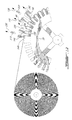
- FIG. 1 is a schematic side elevational view of a portion of a stator mounted to an insertion system according to a first illustrative embodiment
- FIG. 2 is a schematic side elevational view similar to FIG. 1 illustrating the insertion of paper in a slot of the stator using the first leg of a prewound coil; the insertion of a prewound coil; the insertion an interphase insulation paper and the insertion of a wedge;
- FIG. 3 is a schematic side elevational view similar to FIG. 2 illustrating the completion of the insertions
- FIG. 4 is a schematic side elevational view similar to FIG. 1 illustrating the removal of the various pushing elements
- FIG. 5 is a schematic side elevational view similar to FIG. 1 illustrating the rotation of the stator of a predetermined angle; the loading of a prewound coil; the loading of an interphase insulation paper and the loading of a wedge;
- FIG. 6 is a schematic side elevational view of a portion of a stator mounted to an insertion system according to a second illustrative embodiment; this figure illustrating the lowering of a first prewound coil guide;
- FIG. 7 is a schematic side elevational view similar to FIG. 6 illustrating the loading the loading of a prewound coil; the loading of an interphase insulation paper and the loading of a wedge;
- FIG. 8 is a schematic side elevational view similar to FIG. 6 illustrating the beginning of the insertion of the prewound coil
- FIG. 9 is a schematic side elevational view similar to FIG. 6 illustrating the insertion of paper in a slot of the stator using the first leg of a prewound coil; the insertion of a prewound coil; the insertion an interphase insulation paper and the insertion of a wedge;
- FIG. 10 is a schematic side elevational view similar to FIG. 6 illustrating the completion of the insertion of the paper in a slot of the stator, of the prewound coil and of the interphase insulation paper;
- FIG. 11 is a schematic side elevational view similar to FIG. 6 illustrating the raising of the first prewound coil guide
- FIG. 12 is a schematic side elevational view similar to FIG. 6 illustrating the removal of the various pushing elements and of the paper management hook;
- FIG. 13 is a schematic side elevational view similar to FIG. 6 illustrating the rotation of the stator of a predetermined angle
- FIG. 14 is a schematic side elevational view similar to FIG. 6 illustrating the hooking of the insulation paper by the paper management hook;
- FIG. 15 is a schematic side elevational view similar to FIG. 6 illustrating the pulling of a quantity of paper from the roll by the paper management hook;
- FIG. 16 is a schematic side elevational view similar to FIG. 6 illustrating the reverse rotation of the stator of a predetermined angle
- FIG. 17 is a schematic side elevational view of a portion of a stator mounted to an insertion system according to a third illustrative embodiment; this figure illustrating the lowering of a paper clamp;
- FIG. 18 is a schematic perspective view similar to FIG. 17 , illustrating the loading the loading of a prewound coil; the loading of an interphase insulation paper and the loading of a wedge;
- FIG. 19 is a schematic perspective view similar to FIG. 17 , illustrating the beginning of the insertion of the insulation paper, the beginning of the insertion of the prewound coil, the beginning of the insertion of the interphase insulation paper and the insertion of the wedge;
- FIG. 20 is a schematic perspective view similar to FIG. 17 , illustrating the completion of the insertion of the insulation paper in a slot of the stator, the completion of the insertion of the prewound coil and the completion of the insertion of the interphase insulation paper;
- FIG. 21 is a schematic perspective view similar to FIG. 17 , illustrating the removal of the various pushing elements and of the two paper management hooks;
- FIG. 22 is a schematic side elevational view similar to FIG. 17 illustrating the rotation of the stator of a predetermined angle
- FIG. 23 is a schematic side elevational view similar to FIG. 17 illustrating the hooking of the insulation paper by the two paper management hooks;
- FIG. 24 is a schematic side elevational view similar to FIG. 17 illustrating the pulling of a quantity of paper from the roll by the two paper management hooks.
- FIG. 25 is a schematic side elevational view similar to FIG. 17 illustrating the reverse rotation of the stator of a predetermined angle.
- stator holder so configured as to hold the stator
- a prewound coil holder configured and sized to hold the two longitudinal legs of a prewound coil; the prewound coil holder being radially movable between a retracted position and an extended position where each longitudinal leg enters a corresponding longitudinal slot; the continuous insulating paper extending between the prewound coil holder and the stator;
- a method to insert continuous insulating paper and a prewound coil provided with two longitudinal legs in the longitudinal slots of a stator of an electric machine including:
- prewound coil holder configured and sized to hold the two longitudinal legs of a prewound coil; the prewound coil holder being radially movable between a retracted position and an extended position where each longitudinal leg enters a corresponding longitudinal slot;
- the words “comprising” (and any form of comprising, such as “comprise” and “comprises”), “having” (and any form of having, such as “have” and “has”), “including” (and any form of including, such as “include” and “includes”) or “containing” (and any form of containing, such as “contain” and “contains”), are inclusive or open-ended and do not exclude additional, unrecited elements or process steps.
- prewound coil is to be construed herein and in the appended claims as any coil of wire that is prewound before its insertion into the slot of a stator of an electric machine and that is rigid enough to carry out the continuous paper insertion.
- illustrative embodiments described herein are concerned with the insertion of electrically insulating paper from a continuous roll into slots of a stator created by outwardly projecting teeth.
- the insertion of the insulating paper is done by the insertion of prewound coils in the stator slots.
- the electrically insulating paper is not cut prior to its insertion in the slots, thereby completely covering the outer surface of the stator.
- the insertion systems and methods described herein are also optionally concerned with the insertion of interphase insulation paper between the different coils inserted in the stator slots and with the insertion of slot closing wedges.
- FIGS. 1 to 5 of the appended drawings a schematic insertion system 30 according to a first illustrative embodiment will be described.
- the insertion system 30 is designed for inserting continuous insulating paper 32 from a continuous roll 34 of paper in the longitudinal slots 36 of a stator 38 .
- the insertion system 30 includes a rotating stator holder 42 schematically illustrated with four spokes 44 , and two interconnected radially movable prewound coil holding and pushing elements referred to as a prewound coil holder 46 .
- the illustrative insertion system 30 optionally includes a radially movable interphase insulation paper holding element 48 and a radially movable wedge holding element 50 .
- the rotating stator holder 42 may be manually rotated as required if the system 30 is a manual system.
- the rotation of the rotating stator holder 42 could be controlled by a controller (not shown) should the system 30 be computer controlled.
- a controller not shown
- an electric motor such as a stepper motor (not shown) could be used to rotate the rotating stator holder 42 when required.
- the radial movements of the prewound coil holders 46 , of the interphase insulation paper holder 48 and of the wedge holder 50 could be manually done or could be powered by pneumatic or hydraulic cylinders, for example.
- Other mechanical methods of radially moving the holding elements 46 , 48 and 50 under the control of a controller could also be used.
- the holding elements 46 , 48 and 50 use vacuum suction to adequately hold the longitudinal legs 52 A and 52 B of a prewound coil 52 , the interphase insulation paper 54 and the wedge 56 , respectively.
- the vacuum supply may, for example be under the control of a controller (not shown).
- the roll of continuous paper 34 is freewheeling on the paper roll holder 58 .
- the holder 58 could also be mechanically powered to controllably feed paper 32 .
- a controlled tension could be applied to the paper roll holder 58 to prevent unwanted unrolling of the continuous paper 32 .
- FIG. 1 illustrates the stator 38 mounted to the holder 42 and having some of its slots totally or partially filled with insulating paper, prewound coils and wedges.
- the stator 38 is adequately positioned to receive the continuous insulating paper 32 in its slot 36 since the slot 36 is aligned with the first leg 52 A of the prewound coil 52 .
- the coil 52 is mounted to the prewound coil holder 46
- the interphase insulation paper 54 is mounted to the holder 48
- the wedge 56 is mounted to the holder 50 .
- FIG. 2 illustrates the insertion of the continuous insulation paper 32 in the slot 36 via the radial movement of the first leg 52 A of the prewound coil 52 , caused by the radial movement of the prewound coil holders 46 (see arrows 60 ) towards the stator 38 .
- This insertion of the paper 32 in the slot 36 forces some of the continuous paper 32 to be unrolled from the roll 34 (see arrow 62 ).
- both legs 52 A and 52 B of the prewound coil 52 are inserted in adequate slots of the stator 38 .
- the second leg 52 B of the prewound coil 52 pushed by the holder 46 enters a slot 47 of the stator 38 that has insulating paper and the first leg of another prewound coil already inserted therein.
- the insertion of the interphase insulation paper 54 into a slot 55 of the stator 38 also begins by a radial movement of the holder 48 towards the stator 38 (see arrow 64 ). It is to be noted that the slot 55 already contains the first leg of a prewound coil and, after the complete insertion of the interphase insulation paper 54 , is ready to receive the second leg of another prewound coil.
- FIG. 2 also illustrates the insertion of the wedge 56 into a slot 57 , which is filled with the legs of two prewound coils, by the radial movement of the holder 50 towards the stator 38 (see arrow 66 ).
- FIG. 3 illustrates the completion of the insertions of the prewound coil 52 and of the interphase insulation paper 54 as illustrated by arrows 60 and 64 , respectively.
- the insertion system is prepared for the next insertion. More specifically, the holders 46 , 48 and 50 are respectively loaded with a prewound coil 52 , an interphase insulation paper 54 and a wedge 56 .
- the stator 38 is also rotated (see arrow 70 ) so that an adjacent stator slot 72 is aligned with the first leg of the coil 52 . It is to be noted that this rotation of the stator 38 cause some continuous paper 32 to be unrolled from the roll 34 (see arrow 74 ).
- FIGS. 6 to 16 of the appended drawings an insertion system 100 according to a second illustrative embodiment will be described. Since the continuous paper insertion system 100 is very similar to the continuous paper insertion system 30 described hereinabove, only the differences therebetween will be described hereinbelow.
- the main difference between the insertion system 100 and the insertion system 30 is that the insertion system 100 includes prewound coil guide assemblies 102 and 104 to control the insertion of the prewound coils and a paper management hook 106 to control the paper unrolling from the continuous paper roll 34 .
- the prewound coil guide assembly 102 includes a first guide 108 and a second guide 110 that are radially mobile and that are so configured and positioned as to define a passageway 112 therebetween.
- the passageway 112 is sized to receive a first leg of a prewound coil.
- the assembly 102 also includes a radially mobile pushing element 113 .
- the first guide 108 is slightly longer than the second guide 110 so as to make contact with the paper 32 when the guide assembly 102 is radially moved towards the stator 38 . It is to be noted that the radial movements of the prewound coil guide assembly 102 may be controlled by a controller (not shown) or be manually actuated.
- the prewound coil guide assembly 104 includes a first guide 114 and a second guide 116 that are so configured and positioned as to define a passageway 118 therebetween.
- the passageway 118 is sized to receive a second leg of a prewound coil.
- the assembly 104 also includes a radially mobile pushing element 119 .
- the prewound coil guide assemblies 102 , 104 and the radially mobile pushing elements 113 and 119 form a prewound coil holder.
- the paper management hook 106 includes a paper contacting portion 120 so configured and sized as to releasably hook the continuous paper 32 .
- the paper management hook 106 may be moved along an axis 122 as will be described hereinbelow. It is to be noted that the movements of the hook 106 along axis 122 may be controlled by a controller (not shown) or be manually actuated.
- FIG. 6 shows a predetermined length 124 of paper 32 that has been hooked by the hook 106 and pulled from the roll 34 .
- the first prewound coil guide assembly 102 is then moved towards the stator 38 (see arrows 126 ) until the guide 108 clamps the paper 32 to the stator 38 to prevent further unrolling of the paper 32 from the roll 34 .
- FIG. 7 illustrates the loading of a prewound coil 52 between the guide assemblies 102 and 104 ; the loading of an interphase insulation paper 54 to the holder 48 and the loading of a wedge 56 to the holder 50 .
- FIG. 8 illustrates the beginning of the insertion of the prewound coil 52 by the pushing action of the pushing elements 113 and 119 (see arrows 128 ).
- FIG. 8 illustrates the system 100 when the first leg of the prewound coil 52 enters in contact with the paper 32 .
- FIG. 9 illustrates the insertion of the paper 32 in the slot 36 of the stator using the first leg of a prewound coil 52 .
- the pushing element 113 pushes onto the prewound coil 52 (see arrow 128 ) that, in turn, pushes the paper 32 in the slot 36 .
- the coil 52 is inserted in the slot 36 by the same movement. Since the guide 108 prevents paper from being unrolled from the roll 34 , the paper entering the slot 36 comes from the length of paper 124 hooked to the paper management hook 106 that moves towards the stator 38 (see arrow 130 ).
- the second leg of the prewound coil 52 guided by the second guide assembly 104 enters a slot of the stator 38 that has insulating paper and the first leg of another prewound coil already inserted therein.
- FIG. 9 also illustrates the beginning of the insertion of the interphase insulation paper 54 (see arrow 132 ) and the insertion of the wedge 56 (see arrow 134 ).
- FIG. 10 illustrates the completion of the insertion of the paper 32 and of the first leg of the prewound coil 52 in the slot 36 of the stator 38 (see arrow 128 ). Again, the paper entering the slot 36 comes from the length of paper hooked to the hook 106 (see arrow 130 ).
- FIG. 10 also illustrates the end of the insertion of the interphase insulation paper 54 (see arrow 132 ).
- the first prewound guide assembly 102 may then be moved away from the stator 38 (see arrows 135 in FIG. 11 ).
- the first prewound guide assembly 102 may then be moved away from the stator 38 (see arrows 135 in FIG. 11 ).
- the guide 108 is required to be moved away to free the paper 32 .
- FIG. 12 illustrate the removal of the various pushing elements 113 , 119 of the holders 48 , 50 and of the paper management hook 106 (see arrows 136 - 138 , 140 - 142 and 144 , respectively).
- FIG. 13 shows the rotation of the stator 38 of a predetermined angle (see arrow 152 ) so that the next slot 154 to receive the first leg of a prewound coil is aligned with the movement axis 122 of the paper management hook 106 .
- rotation of the stator 38 causes some paper 32 to be unrolled from the roll 34 .
- the paper management hook 106 moves in the slot 154 (see arrow 156 ) so that the paper contacting portion 120 hooks with the paper 32 .
- a predetermine length of paper may be unrolled from the roll 34 (see arrow 158 ) by the pulling action of the paper management hook 106 along axis 122 (see arrow 160 ).
- FIG. 16 illustrates the reverse rotation of the stator 38 (see arrow 162 ) of a predetermined angle so as to position the slot 154 in alignment with the passageway 112 of the first prewound coil guide assembly 102 .
- FIGS. 6 to 16 can then be repeated until all the slots of the stator are filled, as described hereinabove.
- FIGS. 17-25 of the appended drawings an insertion system 200 according to a third illustrative embodiment will be described.
- the insertion system 200 includes a second paper management hook 202 and a paper clamp 204 selectively preventing paper 32 to be unrolled from the paper roll 34 during the insertion process. Accordingly, both guides of the first prewound coil guide assembly 206 are the same length.
- the second paper management hook 202 is similar to the paper management hook 106 but is located on the other side of the first prewound coil guide assembly 206 and the displacement axis of this hook is generally radial.
- FIG. 17 shows a first predetermined length 208 of paper 32 that has been hooked by the paper management hook 106 and second predetermined length 210 of paper 32 that has been hooked by the second paper management hook 202 .
- the paper clamp 204 is then moved towards the stator 38 (see arrows 212 ) until the paper 32 is clamped to the stator 38 to prevent further unrolling of the paper 32 from the roll 34 .
- FIG. 18 illustrates the loading of a prewound coil 52 between the guide assemblies 206 and 104 ; the loading of an interphase insulation paper 54 to the holder 48 and the loading of a wedge 56 to the holder 50 .
- FIG. 19 illustrates the insertion of the prewound coil 52 by the pushing action of the pushing elements 113 and 119 (see arrows 214 ) onto the prewound coil.
- the pushing element 113 pushes onto the prewound coil 52 that, in turn, pushes the paper 32 in the slot 36 .
- the coil 52 is inserted in the slot 36 by the same movement. Since the paper clamp 204 prevents paper 32 from being unrolled from the roll 34 , the paper entering the slot 36 comes from the first and second lengths of paper 208 and 210 hooked to the paper management hooks 106 and 202 that move towards the stator 38 (see arrows 216 and 218 ).
- the second leg of the prewound coil 52 guided by the second guide assembly 104 enters a slot of the stator 38 that has insulating paper and the first leg of another prewound coil already inserted therein.
- FIG. 19 also illustrates the beginning of the insertion of the interphase insulation paper 54 (see arrow 220 ) and the insertion of the wedge 56 (see arrow 222 ).
- FIG. 20 illustrates the completion of the insertion of the paper 32 and of the first leg of the prewound coil 52 in the slot 36 of the stator 38 (see arrow 214 ). Again, the paper entering the slot 36 comes from the length of paper hooked to the hooks 106 and 202 (see arrows 216 and 218 ).
- FIG. 20 also illustrates the end of the insertion of the interphase insulation paper 54 (see arrow 220 ).
- FIG. 21 illustrate the removal of the various pushing elements 113 , 119 ; of the holders 48 , 50 ; of the paper management hooks 106 , 202 and of the paper clamp 204 (see arrows 224 - 226 , 228 - 230 , 232 - 234 and 236 , respectively).
- FIG. 22 shows the rotation of the stator 38 of a predetermined angle (see arrow 238 ) so that the next slot 240 to receive the first leg of a prewound coil is aligned with the movement axis 122 of the paper management hook 106 .
- rotation of the stator 38 causes some paper 32 to be unrolled from the roll 34 (see arrow 242 ).
- the paper management hook 106 moves in the slot 240 (see arrow 244 ) so that the paper contacting portion 120 hooks with the paper 32 .
- the second paper management hook 202 moves so that its paper contacting portion 246 hooks the paper 32 (see arrow 248 ).
- a predetermined length of paper may be unrolled from the roll 34 (see arrow 250 ) by the pulling action of the paper management hooks 106 and 202 (see arrows 252 and 254 ) and provided on each side of the first prewound coil guide assembly 206 .
- FIG. 25 illustrates the reverse rotation of the stator 38 (see arrow 256 ) of a predetermined angle so as to position the slot 240 in alignment with the passageway 112 of the first prewound coil guide assembly 206 .
- FIGS. 17 to 25 can then be repeated until all the slots of the stator are filled, as described hereinabove.
- the paper could be pre-cut to a predetermined length sufficient to cover the entire stator.
- the size of the coils and the number of stator slots present between each longitudinal legs of the coils could be different from illustrated herein.
Landscapes
- Engineering & Computer Science (AREA)
- Power Engineering (AREA)
- Manufacturing & Machinery (AREA)
- Manufacture Of Motors, Generators (AREA)
- Insulation, Fastening Of Motor, Generator Windings (AREA)
Priority Applications (1)
| Application Number | Priority Date | Filing Date | Title |
|---|---|---|---|
| US13/266,311 US8601676B2 (en) | 2009-06-29 | 2010-06-28 | Insertion system and method to insert insulators and coils in the slots of the stator of an electric machine |
Applications Claiming Priority (3)
| Application Number | Priority Date | Filing Date | Title |
|---|---|---|---|
| US21364009P | 2009-06-29 | 2009-06-29 | |
| PCT/CA2010/001025 WO2011000103A1 (fr) | 2009-06-29 | 2010-06-28 | Systèmes et procédés d'insertion d'isolateurs et de bobines dans les encoches du stator d'une machine électrique |
| US13/266,311 US8601676B2 (en) | 2009-06-29 | 2010-06-28 | Insertion system and method to insert insulators and coils in the slots of the stator of an electric machine |
Publications (2)
| Publication Number | Publication Date |
|---|---|
| US20120117790A1 US20120117790A1 (en) | 2012-05-17 |
| US8601676B2 true US8601676B2 (en) | 2013-12-10 |
Family
ID=43410412
Family Applications (1)
| Application Number | Title | Priority Date | Filing Date |
|---|---|---|---|
| US13/266,311 Active 2030-11-16 US8601676B2 (en) | 2009-06-29 | 2010-06-28 | Insertion system and method to insert insulators and coils in the slots of the stator of an electric machine |
Country Status (4)
| Country | Link |
|---|---|
| US (1) | US8601676B2 (fr) |
| EP (1) | EP2449658A4 (fr) |
| CN (1) | CN102474161B (fr) |
| WO (1) | WO2011000103A1 (fr) |
Cited By (1)
| Publication number | Priority date | Publication date | Assignee | Title |
|---|---|---|---|---|
| WO2024083283A1 (fr) * | 2022-10-17 | 2024-04-25 | Schaeffler Technologies AG & Co. KG | Procédé et dispositif de fabrication d'un stator d'une machine électrique rotative, stator et machine électrique rotative |
Families Citing this family (15)
| Publication number | Priority date | Publication date | Assignee | Title |
|---|---|---|---|---|
| CN102185415B (zh) * | 2011-05-17 | 2013-09-11 | 绍兴市雪花机电有限公司 | 定子槽盖纸贮存杯自动插入机的控制系统 |
| JP5761690B2 (ja) * | 2011-12-15 | 2015-08-12 | アイシン・エィ・ダブリュ株式会社 | ステータ製造方法及びコイル挿入装置 |
| US9973063B2 (en) | 2015-10-09 | 2018-05-15 | General Electric Company | Combined stator wedge driver and bar jacking tool |
| US11424667B2 (en) * | 2015-12-15 | 2022-08-23 | Grob-Werke Gmbh & Co. Kg | Method for introducing insulating film and at least one electrical conductor |
| CN106002942B (zh) * | 2016-06-23 | 2018-05-04 | 泉州泓程商贸有限公司 | 一种电机插纸工业机器人 |
| CN105965479B (zh) * | 2016-06-23 | 2017-12-22 | 哈工大机器人集团(哈尔滨)资产经营管理有限公司 | 一种配电站用电动机双向同步插纸智能机器人 |
| CN106002941B (zh) * | 2016-06-23 | 2018-07-10 | 张四玉 | 一种六自由度单向插纸工业机器人专用机械手 |
| GB2560757B (en) * | 2017-03-24 | 2021-04-14 | Jaguar Land Rover Ltd | Stator tooth assembly and associated method and apparatus |
| DE102017129474A1 (de) * | 2017-12-11 | 2019-06-13 | Grob-Werke Gmbh & Co. Kg | Verfahren und Vorrichtung zum Herstellen von Nutisolierungen für Windungsnuten eines Bauteils einer elektrischen Maschine |
| JP7058208B2 (ja) * | 2018-11-12 | 2022-04-21 | 本田技研工業株式会社 | 絶縁紙の装着方法、絶縁紙及びステータ |
| EP3654497A1 (fr) | 2018-11-15 | 2020-05-20 | Black & Decker Inc. | Insert de rétention d'enroulement pour moteur sans balai |
| JP7410753B2 (ja) * | 2020-03-04 | 2024-01-10 | 東芝産業機器システム株式会社 | 絶縁部材、及び、固定子 |
| DE102020119303A1 (de) * | 2020-07-22 | 2022-01-27 | Schaeffler Technologies AG & Co. KG | Verfahren und Vorrichtung zum Einbringen isolierter Wickelpakete in Stator- oder Rotornuten, sowie Stator oder Rotor mit isolierten Wickelpaketen |
| CN113315329B (zh) * | 2021-07-29 | 2021-10-08 | 南通金驰机电有限公司 | 一种定子绝缘纸推入用送纸装置 |
| DE102022204821A1 (de) | 2022-05-17 | 2023-11-23 | Zf Friedrichshafen Ag | Einbringvorrichtung für einen Isolierstreifen bei der Herstellung von Stator- und Rotorwicklungen |
Citations (3)
| Publication number | Priority date | Publication date | Assignee | Title |
|---|---|---|---|---|
| US1661355A (en) | 1926-03-29 | 1928-03-06 | Delcc Remy Corp | Method and machine for lining an armature core with a flexible strip |
| US6154950A (en) * | 1997-03-06 | 2000-12-05 | Denso Corporation | Rotor production method including assembling a slot insulator and coil trunk into a set prior to insertion into an armature core |
| US7185413B2 (en) * | 2001-07-31 | 2007-03-06 | Aisin Aw Co., Ltd. | Motor manufacturing method |
-
2010
- 2010-06-28 EP EP10793480.4A patent/EP2449658A4/fr not_active Withdrawn
- 2010-06-28 US US13/266,311 patent/US8601676B2/en active Active
- 2010-06-28 WO PCT/CA2010/001025 patent/WO2011000103A1/fr active Application Filing
- 2010-06-28 CN CN201080029336.0A patent/CN102474161B/zh not_active Expired - Fee Related
Patent Citations (4)
| Publication number | Priority date | Publication date | Assignee | Title |
|---|---|---|---|---|
| US1661355A (en) | 1926-03-29 | 1928-03-06 | Delcc Remy Corp | Method and machine for lining an armature core with a flexible strip |
| US6154950A (en) * | 1997-03-06 | 2000-12-05 | Denso Corporation | Rotor production method including assembling a slot insulator and coil trunk into a set prior to insertion into an armature core |
| US6510603B1 (en) | 1997-03-06 | 2003-01-28 | Denson Corporation | Rotor production method including assembling a slot insulator and coil trunk into a set prior to insertion into an armature core |
| US7185413B2 (en) * | 2001-07-31 | 2007-03-06 | Aisin Aw Co., Ltd. | Motor manufacturing method |
Cited By (1)
| Publication number | Priority date | Publication date | Assignee | Title |
|---|---|---|---|---|
| WO2024083283A1 (fr) * | 2022-10-17 | 2024-04-25 | Schaeffler Technologies AG & Co. KG | Procédé et dispositif de fabrication d'un stator d'une machine électrique rotative, stator et machine électrique rotative |
Also Published As
| Publication number | Publication date |
|---|---|
| CN102474161A (zh) | 2012-05-23 |
| EP2449658A4 (fr) | 2016-03-02 |
| CN102474161B (zh) | 2014-03-12 |
| US20120117790A1 (en) | 2012-05-17 |
| EP2449658A1 (fr) | 2012-05-09 |
| WO2011000103A1 (fr) | 2011-01-06 |
Similar Documents
| Publication | Publication Date | Title |
|---|---|---|
| US8601676B2 (en) | Insertion system and method to insert insulators and coils in the slots of the stator of an electric machine | |
| KR101078489B1 (ko) | 코일 형성 장치 및 코일 형성 방법 | |
| US7941910B2 (en) | Method for removing winding conductors from a twisting machine and placing them in a rotor stator stack | |
| EP0188601B1 (fr) | Stators enroules sans rainures ni denture et leurs methodes de production | |
| US8875381B2 (en) | Method of manufacturing rotary electric machine | |
| EP2849319A1 (fr) | Procédé de fabrication pour machine électrique rotative | |
| EP1852958A2 (fr) | Procédé de façonage de bobines monocouches | |
| GB2263653A (en) | Making armatures for electrodynamic machines | |
| TWI326149B (fr) | ||
| JP2009254137A (ja) | インナーロータ型回転電機の分割コア型ステータの組み立て方法 | |
| US7370401B2 (en) | Apparatus and methods for wire coil lead placement | |
| JP2017046373A (ja) | コイルのスロットへの挿入方法、及びコイル挿入装置 | |
| US5022139A (en) | Method of inserting a stator winding into a stator | |
| KR101935622B1 (ko) | 코일 권선·세팅방법, 코일 삽입방법 및 코일 권선·세팅장치 | |
| US6282773B1 (en) | Apparatus for producing winding slot insulators and inserting same into the stator core of an electromechanical machine | |
| JP2003319622A (ja) | 回転電機用固定子コイルの製造方法および製造装置 | |
| JPH0642770B2 (ja) | 鉄心内に中間絶縁体を配置するための方法及び装置 | |
| JP4403714B2 (ja) | コイル形成挿入装置及びコイル形成挿入方法 | |
| US11411477B2 (en) | Coil insertion method and coil insertion device | |
| EP0124267A2 (fr) | Dispositif d'insertion des enroulements et de l'isolation | |
| EP0206211A2 (fr) | Méthode et appareil pour enrouler et insérer des bobines dans un noyau statorique de machine dynamo-électrique | |
| US6923399B1 (en) | Manufacturing methods and apparatus for terminating dynamo-machine component wire coil leads | |
| CN111669015B (zh) | 自动绕线系统及自动绕线方法 | |
| WO2010040220A1 (fr) | Système et procédé d'insertion d'isolants dans les encoches du stator d'une machine électrique et stator résultant | |
| JP3140656B2 (ja) | 巻線方法 |
Legal Events
| Date | Code | Title | Description |
|---|---|---|---|
| AS | Assignment |
Owner name: TM4, INC., CANADA Free format text: ASSIGNMENT OF ASSIGNORS INTEREST;ASSIGNORS:CARPENTIER, BRUNO;HOULE, MARTIN;POULIN, STEPHANE;SIGNING DATES FROM 20091206 TO 20091214;REEL/FRAME:027483/0886 |
|
| STCF | Information on status: patent grant |
Free format text: PATENTED CASE |
|
| FPAY | Fee payment |
Year of fee payment: 4 |
|
| AS | Assignment |
Owner name: DANA TM4 INC., CANADA Free format text: CHANGE OF NAME;ASSIGNOR:TM4 INC.;REEL/FRAME:053729/0287 Effective date: 20200301 |
|
| MAFP | Maintenance fee payment |
Free format text: PAYMENT OF MAINTENANCE FEE, 8TH YEAR, LARGE ENTITY (ORIGINAL EVENT CODE: M1552); ENTITY STATUS OF PATENT OWNER: LARGE ENTITY Year of fee payment: 8 |