US8568943B2 - Method of preparing a fuel cell unitized electrode assembly by ultrasonic welding - Google Patents
Method of preparing a fuel cell unitized electrode assembly by ultrasonic welding Download PDFInfo
- Publication number
- US8568943B2 US8568943B2 US12/087,036 US8703608A US8568943B2 US 8568943 B2 US8568943 B2 US 8568943B2 US 8703608 A US8703608 A US 8703608A US 8568943 B2 US8568943 B2 US 8568943B2
- Authority
- US
- United States
- Prior art keywords
- thermoplastic polymer
- electrode assembly
- uea
- sandwich
- gdl
- Prior art date
- Legal status (The legal status is an assumption and is not a legal conclusion. Google has not performed a legal analysis and makes no representation as to the accuracy of the status listed.)
- Active, expires
Links
Images


Classifications
-
- B—PERFORMING OPERATIONS; TRANSPORTING
- B29—WORKING OF PLASTICS; WORKING OF SUBSTANCES IN A PLASTIC STATE IN GENERAL
- B29C—SHAPING OR JOINING OF PLASTICS; SHAPING OF MATERIAL IN A PLASTIC STATE, NOT OTHERWISE PROVIDED FOR; AFTER-TREATMENT OF THE SHAPED PRODUCTS, e.g. REPAIRING
- B29C65/00—Joining or sealing of preformed parts, e.g. welding of plastics materials; Apparatus therefor
- B29C65/72—Joining or sealing of preformed parts, e.g. welding of plastics materials; Apparatus therefor by combined operations or combined techniques, e.g. welding and stitching
-
- H—ELECTRICITY
- H01—ELECTRIC ELEMENTS
- H01M—PROCESSES OR MEANS, e.g. BATTERIES, FOR THE DIRECT CONVERSION OF CHEMICAL ENERGY INTO ELECTRICAL ENERGY
- H01M8/00—Fuel cells; Manufacture thereof
- H01M8/02—Details
- H01M8/0271—Sealing or supporting means around electrodes, matrices or membranes
- H01M8/0276—Sealing means characterised by their form
-
- H—ELECTRICITY
- H01—ELECTRIC ELEMENTS
- H01M—PROCESSES OR MEANS, e.g. BATTERIES, FOR THE DIRECT CONVERSION OF CHEMICAL ENERGY INTO ELECTRICAL ENERGY
- H01M8/00—Fuel cells; Manufacture thereof
- H01M8/02—Details
- H01M8/0271—Sealing or supporting means around electrodes, matrices or membranes
- H01M8/028—Sealing means characterised by their material
- H01M8/0284—Organic resins; Organic polymers
-
- H—ELECTRICITY
- H01—ELECTRIC ELEMENTS
- H01M—PROCESSES OR MEANS, e.g. BATTERIES, FOR THE DIRECT CONVERSION OF CHEMICAL ENERGY INTO ELECTRICAL ENERGY
- H01M8/00—Fuel cells; Manufacture thereof
- H01M8/02—Details
- H01M8/0271—Sealing or supporting means around electrodes, matrices or membranes
- H01M8/0286—Processes for forming seals
-
- H—ELECTRICITY
- H01—ELECTRIC ELEMENTS
- H01M—PROCESSES OR MEANS, e.g. BATTERIES, FOR THE DIRECT CONVERSION OF CHEMICAL ENERGY INTO ELECTRICAL ENERGY
- H01M8/00—Fuel cells; Manufacture thereof
- H01M8/02—Details
- H01M8/0297—Arrangements for joining electrodes, reservoir layers, heat exchange units or bipolar separators to each other
-
- H—ELECTRICITY
- H01—ELECTRIC ELEMENTS
- H01M—PROCESSES OR MEANS, e.g. BATTERIES, FOR THE DIRECT CONVERSION OF CHEMICAL ENERGY INTO ELECTRICAL ENERGY
- H01M8/00—Fuel cells; Manufacture thereof
- H01M8/10—Fuel cells with solid electrolytes
- H01M8/1004—Fuel cells with solid electrolytes characterised by membrane-electrode assemblies [MEA]
-
- Y—GENERAL TAGGING OF NEW TECHNOLOGICAL DEVELOPMENTS; GENERAL TAGGING OF CROSS-SECTIONAL TECHNOLOGIES SPANNING OVER SEVERAL SECTIONS OF THE IPC; TECHNICAL SUBJECTS COVERED BY FORMER USPC CROSS-REFERENCE ART COLLECTIONS [XRACs] AND DIGESTS
- Y02—TECHNOLOGIES OR APPLICATIONS FOR MITIGATION OR ADAPTATION AGAINST CLIMATE CHANGE
- Y02E—REDUCTION OF GREENHOUSE GAS [GHG] EMISSIONS, RELATED TO ENERGY GENERATION, TRANSMISSION OR DISTRIBUTION
- Y02E60/00—Enabling technologies; Technologies with a potential or indirect contribution to GHG emissions mitigation
- Y02E60/30—Hydrogen technology
- Y02E60/50—Fuel cells
-
- Y—GENERAL TAGGING OF NEW TECHNOLOGICAL DEVELOPMENTS; GENERAL TAGGING OF CROSS-SECTIONAL TECHNOLOGIES SPANNING OVER SEVERAL SECTIONS OF THE IPC; TECHNICAL SUBJECTS COVERED BY FORMER USPC CROSS-REFERENCE ART COLLECTIONS [XRACs] AND DIGESTS
- Y02—TECHNOLOGIES OR APPLICATIONS FOR MITIGATION OR ADAPTATION AGAINST CLIMATE CHANGE
- Y02P—CLIMATE CHANGE MITIGATION TECHNOLOGIES IN THE PRODUCTION OR PROCESSING OF GOODS
- Y02P70/00—Climate change mitigation technologies in the production process for final industrial or consumer products
- Y02P70/50—Manufacturing or production processes characterised by the final manufactured product
Definitions
- This invention relates to a unitized electrode assembly (UEA) for a fuel cell which is produced by utilizing a film of thermoplastic polymer, such as polyethylene, polypropylene, or other easily melted high flowing plastic, layered around the cathode and anode gas diffusion layers (GDLs).
- Ultrasonic welding such as vertical vibrational pressure, is utilized to heat the edge areas of the UEA planform, causing the plastic to diffuse through the GDLs and the electrode catalysts, thereby forming a solid plastic edge serving as a fluid seal of the UEA.
- Fuel cell power plants that employ a polymer, proton exchange membrane electrolyte (PEM) include a cathode electrode on one side of the PEM and an anode electrode on the other side of the PEM, the electrodes comprising suitable catalysts so as to convert hydrogen and oxygen reactant gases into electricity and water, all as is known.
- the reactants reach the membrane by means of reactant gas flow field plates, sometimes referred to as water transport plates, and thence gas diffusion layers (GDLs), occasionally referred to as substrates.
- the GDLs are adjacent to respective sides of the electrodes.
- the membrane may typically be a fluorinated polymer, such as that sold under the name NAFION®.
- the electrodes are typically a mixture of polymer and noble metal, as is known.
- a recent innovation is to manufacture a unitized electrode assembly (UEA), including the anode and cathode GDLs and electrodes, on respective sides of the membrane, unitized and sealed into a single structure, using thermoplastics.
- Thermoplastics only undergo a change of state (liquefy) when at a high temperature and return to a solid state when cooled, and can be re-melted and reformed. This is in contrast with thermoset plastics, which, when formed, undergo an irreversible chemical change, and cannot be reformed with heat.
- thermoplastics use localized heating of the thermoplastics to be joined causing melting, followed by resolidification at the interface.
- Laser or IR welding directs a beam of laser or IR through a transparent thermoplastic causing surface heating of an opaque thermoplastic at the interface of the two thermoplastics. When the interface reaches a sufficient temperature, the plastics begin to melt and bond together by interflow.
- Radio Frequency welding also called “High Frequency” welding relies on the dissipation of some of the energy of a changing electromagnetic field in an imperfect dielectric to heat the plastic; subsequent cooling causes two plastics to be joined together.
- one or both of the plastic pieces to be joined is/are held against a hot plate until softening begins.
- the plastic is removed from the hot plate and placed against the mating surface and held until cooled.
- Ultrasonic welding is defined as employing mechanical oscillations between 16 kHz and 1 GHz. Typical ultrasonic welding machines operate in the 15 kHz to 70 kHz range and most commonly around 20 kHz. A generator produces electrical oscillations at the desired frequency, which are then transferred to a converter in which crystals expand and contract creating mechanical vibrations at the same frequency. These vibrations are transferred to a horn that contacts the stack of plastic parts to be welded. As the horn moves vertically up and down, perpendicular to the plane of the parts, heat friction develops along the joining area between the two plastic parts that melts the plastic and joins the parts.
- thermoplastics respond the same to ultrasonic welding. Those that have an amorphous polymer structure, characterized by random arrangement of molecules, will have a broader softening and melting point and transfer ultrasonic vibrations well.
- thermoplastics are polystyrene, polyetherimide and low density polyethylene. Thermoplastic polymers of a semi-crystalline nature have more ordered structure and well-defined melting points and do not transfer ultrasonic vibrations as well and are therefore harder to weld.
- thermoplastics are polyester, polyethylene, and linear low density polyethylene (LLDPE). In general, high melting point and low melt index polymers are more difficult to weld.
- a “press plate” method for manufacturing a UEA involves laying out a complete UEA with polyethylene films between the various layers and on the exterior of the GDLs. Then, press plates apply pressure to the assembly as the press plates are heated to on the order of 150° C. (320° F.). Thereafter, the press plates must be cooled before pressure is released and the sealed UEA removed from the press plates. This process typically takes at least ten and as much as sixty minutes per UEA manufactured. The process is costly and consumes manufacturing floor space. In addition, the process is inefficient in that it requires heating of the entire planform in addition to the press plates. It is known that elevated temperature causes degradation of the PEM, and thus the durability of the UEA is reduced as a consequence of heating of the entire planform of the UEA during manufacture.
- thermoplastic polymer Another method utilizing injection molding or compression molding of a thermoplastic polymer is disclosed in patent application PCT/US03/01796, International Publication No. WO03/063280 A2. This process may require pre-treating such as corona treatment, oxygen plasma treatment or fluoropolymer dispersions. There are additional problems of the fountain-flow thermoplastics readjusting the positioning of components, and the like. These and other problems require additional processing techniques in order to cause successful manufacture of UEAs.
- Objects of the invention include: a method of manufacturing a fuel cell UEA which heats only the outside edge of the UEA which is to be sealed; providing a UEA without subjecting the PEM to elevated temperatures; providing manufacture of a UEA in short cycle times; avoiding the necessity of heating and cooling press plates, as well as the entire UEA, in the manufacture of a UEA; manufacturing UEAs for fuel cells with a single, exclusive method; and improved fuel cell UEAs.
- thermoplastic polymers such as polyethylene
- when heated by vibrational energy will impregnate carbon fiber of gas diffusion layers and diffuse into the porous catalyst/polymer electrode layers adjacent to the PEMs, thereby forming a solid plastic seal of the entire permeable edge volume of a UEA.
- an easily melted, free-flowing thermoplastic polymer film such as polyethylene film
- a suitable non-melting release film being placed on the upper and lower surfaces of the UEA sandwich
- the thermoplastic polymer film is melted by vibrational energy applied only to the edges of the UEA sandwich, that is, adjacent to the plastic film
- the vibrating energy melts the film and pressure applied at the same time causes the thermoplastic polymer to impregnate the GDLs, and diffuse into the adjacent porous catalyst layers, forming a mechanical bond therewith.
- the edges of the GDLs are impregnated with a thermoplastic and then laid up in a sandwich adjacent to the electrodes, with the PEM between the electrodes and release film on the upper and lower surfaces.
- the vibrational energy is applied with compression to form the UEA, as in the first form of the invention described hereinbefore, using the thermoplastic preformed into the GDLs.
- the UEA is formed one edge at a time by an ultrasonic welder having a straight vibrating anvil; in another form, the invention may be practiced utilizing an ultrasonic welder having a frame-shaped vibrating anvil. Other combinations of edges may also be welded using this invention.
- the invention avoids subjecting the active area of the UEA to elevated temperature which might reduce the durability of the polymer exchange membrane.
- the melting, impregnating, diffusion and cooling to make a UEA according to the invention requires only on the order of five seconds.
- the invention permits cycle times on the order of one-half minute to several minutes, and uses less energy than prior art assembly methods.
- the invention may be used to make unitized assemblies for electrochemical cells other than fuel cells, such as electrolyzers.
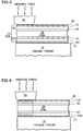
- FIG. 1 is a perspective view of a unitized electrode assembly made in accordance with the process of the present invention.
- FIG. 2 is a partial, sectioned side elevation view, with sectioning lines omitted for clarity, taken on the line A-A in FIG. 1 , before unitization.
- FIG. 3 is a partial, sectioned side elevation view, with sectioning lines omitted for clarity, of the section of FIG. 2 when the UEA is completed.
- FIG. 4 is a partial, sectioned side elevation view, with sectioning lines omitted for clarity, of a first alternative to the method of FIGS. 2 and 3 .
- FIG. 5 is a partial, sectioned side elevation view, with sectioning lines omitted for clarity, of a second alternative to the method of FIGS. 2 and 3 .
- FIG. 6 is a partial, sectioned side elevation view, with sectioning lines omitted for clarity, of a second form of the invention.
- a unitized electrode assembly 9 made in accordance with the process of the present invention includes a reactant gas flow distribution layer herein referred to as a gas diffusion layer (GDL) 12 , and an integrated seal 13 ; holes 15 , 16 register the various layers during the process of forming the seal 13 .
- the seal 13 extends around the edge of the entire periphery of the unitized electrode assembly 9 .
- the unitized electrode assembly might be on the order of 8 cm by 14 cm, and the seal may be formed to have a width of 2 cm-3 cm when formed, and then the UEA may be trimmed so that the seal width is on the order of 8 mm-10 mm.
- the process comprises laying up the various components as illustrated in FIG. 2 , above a holding fixture, which has pins to receive the registering holes 15 , 16 .
- a release film 21 which may be TEFLON®, KAPTON®, or any other high temperature plastic film which will not melt or stick to the polyethylene, including a film of high temperature polyethylene.
- a first layer 22 of thermoplastic polymer film which may extend a variety of distances from the edge sufficient to form a fluid edge seal; in this embodiment the film 22 may extend on the order of two or three centimeters in from the edge of the UEA assembly.
- a GDL 23 such as an anode GDL, is positioned above the film 22 .
- a second layer 25 of thermoplastic polymer film is positioned above the GDL 23 .
- An electrode such as an anode electrode 27 , which comprises a conventional fuel cell catalyst, is disposed above the second layer 25 of film.
- the PEM 28 is disposed above the electrode 27 .
- Another electrode such as a cathode electrode 30 , is positioned above the PEM 28 .
- a third layer 32 of thermoplastic polymer film is positioned above the electrode 30 .
- a second GDL 12 such as a cathode GDL, is disposed above the third layer of film 32 .
- a fourth layer 35 of thermoplastic polymer film is positioned above the second GDL 12 .
- a release film 36 is positioned at the top of the stack of components.
- the holding fixture 19 is part of an ultrasonic welding machine which has an anvil 40 that provides a vertical force as the distance between the fixture 19 and the anvil 40 is varied ultrasonically, by on the order of 2 micrometers to 10 micrometers.
- An available system for serving this purpose is the Branson 2000 IW Ultrasonic Welding System.
- the clamping force may be on the order of 500 kPa (60 psig).
- the vibration may, for instance, be on the order of 20 kHz.
- the anvil may be straight, so that each edge of the UEA is sealed separately, or have a picture frame shape so that four edges of a UEA may be sealed in a single plunge. Other combinations of edge sealing may also be used.
- the polyethylene film becomes completely diffused through the various layers to form an integrated seal 13 , completely impregnated throughout, as is illustrated by stippling in FIG. 3 .
- thermoplastic sheets 25 , 32 may be placed only between each GDL 23 , 12 and the adjacent electrode 27 , 30 , as shown in FIG. 4 . Under pressure and vibration for a suitable time, the melted plastic will impregnate the edge of each GDL from the inside out and diffuse into the electrodes to provide the seal described with respect to FIG. 3 hereinbefore.
- thermoplastic sheets 22 , 35 may be placed outside of the GDLs 23 , 12 , as shown in FIG. 5 .
- the melted plastic will impregnate each GDL from the outside in.
- GDL's 12 a , 23 a are impregnated with thermoplastic polymer, as shown by the stippling, and thereafter laid up in a sandwich with the release film 21 , the anode electrode 27 , the PEM 28 , the cathode electrode 30 , and the release film 36 . Then the vibrating force is applied by the ultrasonic welding machine 19 , 40 .
- thermoplastic polymer may comprise polyethylene, polypropylene or other suitable polymers.
Landscapes
- Engineering & Computer Science (AREA)
- Life Sciences & Earth Sciences (AREA)
- Manufacturing & Machinery (AREA)
- Sustainable Development (AREA)
- Sustainable Energy (AREA)
- Chemical & Material Sciences (AREA)
- Chemical Kinetics & Catalysis (AREA)
- Electrochemistry (AREA)
- General Chemical & Material Sciences (AREA)
- Mechanical Engineering (AREA)
- Fuel Cell (AREA)
- Lining Or Joining Of Plastics Or The Like (AREA)
Priority Applications (1)
| Application Number | Priority Date | Filing Date | Title |
|---|---|---|---|
| US14/028,397 US8921010B2 (en) | 2005-12-29 | 2013-09-16 | Method of preparing a fuel cell unitized electrode assembly by ultrasonic welding |
Applications Claiming Priority (1)
| Application Number | Priority Date | Filing Date | Title |
|---|---|---|---|
| PCT/US2005/047487 WO2007084109A2 (en) | 2005-12-29 | 2005-12-29 | Ultrasonically welded fuel cell unitized electrode assembly |
Related Child Applications (1)
| Application Number | Title | Priority Date | Filing Date |
|---|---|---|---|
| US14/028,397 Division US8921010B2 (en) | 2005-12-29 | 2013-09-16 | Method of preparing a fuel cell unitized electrode assembly by ultrasonic welding |
Publications (2)
| Publication Number | Publication Date |
|---|---|
| US20090169946A1 US20090169946A1 (en) | 2009-07-02 |
| US8568943B2 true US8568943B2 (en) | 2013-10-29 |
Family
ID=38288039
Family Applications (2)
| Application Number | Title | Priority Date | Filing Date |
|---|---|---|---|
| US12/087,036 Active 2028-02-26 US8568943B2 (en) | 2005-12-29 | 2005-12-29 | Method of preparing a fuel cell unitized electrode assembly by ultrasonic welding |
| US14/028,397 Active US8921010B2 (en) | 2005-12-29 | 2013-09-16 | Method of preparing a fuel cell unitized electrode assembly by ultrasonic welding |
Family Applications After (1)
| Application Number | Title | Priority Date | Filing Date |
|---|---|---|---|
| US14/028,397 Active US8921010B2 (en) | 2005-12-29 | 2013-09-16 | Method of preparing a fuel cell unitized electrode assembly by ultrasonic welding |
Country Status (5)
| Country | Link |
|---|---|
| US (2) | US8568943B2 (de) |
| EP (1) | EP1979966A4 (de) |
| JP (1) | JP2009522720A (de) |
| CN (1) | CN101351915A (de) |
| WO (1) | WO2007084109A2 (de) |
Cited By (1)
| Publication number | Priority date | Publication date | Assignee | Title |
|---|---|---|---|---|
| US8921010B2 (en) * | 2005-12-29 | 2014-12-30 | Ballard Power Systems Inc. | Method of preparing a fuel cell unitized electrode assembly by ultrasonic welding |
Families Citing this family (7)
| Publication number | Priority date | Publication date | Assignee | Title |
|---|---|---|---|---|
| US8512907B2 (en) * | 2007-09-27 | 2013-08-20 | Dai Nippon Printing Co., Ltd. | Membrane catalyst layer assembly with reinforcing films, membrane electrode assembly with reinforcing films, and polymer electrolyte fuel cells |
| EP2580799B1 (de) | 2010-06-08 | 2017-03-08 | Rensselaer Polytechnic Institute | Verfahren zur herstellung einer elektrochemischen zelle |
| US9761898B2 (en) * | 2010-09-16 | 2017-09-12 | Toyota Jidosha Kabushiki Kaisha | Membrane electrode assembly, fuel cell using the same and manufacturing method of membrane electrode assembly |
| CN105164839A (zh) * | 2013-02-19 | 2015-12-16 | 百拉得动力系统公司 | 用于制作燃料电池构件的组件和使用该组件的方法 |
| JP6325025B2 (ja) * | 2016-07-05 | 2018-05-16 | 本田技研工業株式会社 | 電解質膜・電極構造体の製造方法 |
| CN109473707B (zh) * | 2017-09-08 | 2022-05-31 | 徐煜 | 质子交换膜燃料电池的质子交换膜 |
| GB202010522D0 (en) * | 2020-07-09 | 2020-08-26 | Johnson Matthey Fuel Cells Ltd | Process of maufacturing a membrane electrode assembly |
Citations (7)
| Publication number | Priority date | Publication date | Assignee | Title |
|---|---|---|---|---|
| US5733678A (en) * | 1993-05-04 | 1998-03-31 | Fraunhofer-Gesellschaft Zur Forderung Der Angewandten Forschung E.V. | Polymer fuel cell |
| US6159628A (en) * | 1998-10-21 | 2000-12-12 | International Fuel Cells Llc | Use of thermoplastic films to create seals and bond PEM cell components |
| JP2002050400A (ja) | 2000-08-03 | 2002-02-15 | Nippei Toyama Corp | 電極体製造装置及び製造方法 |
| US20030091885A1 (en) * | 2001-01-31 | 2003-05-15 | Matsushita Electric Industrial Co., Ltd. | High polymer electrolyte fuel cell and electrolyte film-gasket assembly for the fuel cell |
| US20030203273A1 (en) * | 2002-04-29 | 2003-10-30 | Rajeev Puttaiah | Fuel cell with overmolded electrode assemblies |
| WO2004086543A2 (en) * | 2003-03-25 | 2004-10-07 | E.I. Du Pont Canada Company | Electrochemical cell component |
| JP2005158690A (ja) | 2003-10-27 | 2005-06-16 | Mitsubishi Electric Corp | 燃料電池およびその製造方法 |
Family Cites Families (10)
| Publication number | Priority date | Publication date | Assignee | Title |
|---|---|---|---|---|
| JPH0845517A (ja) * | 1994-07-28 | 1996-02-16 | Tanaka Kikinzoku Kogyo Kk | 高分子電解質型燃料電池用シール構造及びその製造方法 |
| JPH1145729A (ja) * | 1997-07-25 | 1999-02-16 | Fuji Electric Co Ltd | 固体高分子電解質型燃料電池 |
| JPH11204122A (ja) * | 1998-01-19 | 1999-07-30 | Toshiba Corp | 固体高分子電解質型燃料電池 |
| JP2001118592A (ja) * | 1999-10-18 | 2001-04-27 | Matsushita Electric Ind Co Ltd | 高分子電解質型燃料電池及び電池スタック |
| JP2005516342A (ja) * | 2002-01-22 | 2005-06-02 | イー・アイ・デュポン・ドウ・ヌムール・アンド・カンパニー | 膜電極組立体を製造するための圧縮押型 |
| JP4202806B2 (ja) * | 2003-04-09 | 2008-12-24 | 三井化学株式会社 | 電解質膜/電極接合体、その製造法および燃料電池 |
| JP4887597B2 (ja) * | 2003-07-11 | 2012-02-29 | 三菱マテリアル株式会社 | 固体高分子型燃料電池、ガス拡散層用部材およびその製造方法 |
| DE602004031236D1 (de) * | 2003-08-29 | 2011-03-10 | Du Pont | Herstellungsverfahren für eine membranelektrodenanordnungseinheit |
| WO2005117165A1 (en) * | 2004-05-29 | 2005-12-08 | Polymer Technologies Inc. | Separator plate for fuel cell and production system for products for use in fuel cells |
| WO2007084109A2 (en) * | 2005-12-29 | 2007-07-26 | Utc Power Corporation | Ultrasonically welded fuel cell unitized electrode assembly |
-
2005
- 2005-12-29 WO PCT/US2005/047487 patent/WO2007084109A2/en active Application Filing
- 2005-12-29 CN CNA2005800524434A patent/CN101351915A/zh active Pending
- 2005-12-29 EP EP05858734A patent/EP1979966A4/de not_active Withdrawn
- 2005-12-29 JP JP2008548481A patent/JP2009522720A/ja active Pending
- 2005-12-29 US US12/087,036 patent/US8568943B2/en active Active
-
2013
- 2013-09-16 US US14/028,397 patent/US8921010B2/en active Active
Patent Citations (7)
| Publication number | Priority date | Publication date | Assignee | Title |
|---|---|---|---|---|
| US5733678A (en) * | 1993-05-04 | 1998-03-31 | Fraunhofer-Gesellschaft Zur Forderung Der Angewandten Forschung E.V. | Polymer fuel cell |
| US6159628A (en) * | 1998-10-21 | 2000-12-12 | International Fuel Cells Llc | Use of thermoplastic films to create seals and bond PEM cell components |
| JP2002050400A (ja) | 2000-08-03 | 2002-02-15 | Nippei Toyama Corp | 電極体製造装置及び製造方法 |
| US20030091885A1 (en) * | 2001-01-31 | 2003-05-15 | Matsushita Electric Industrial Co., Ltd. | High polymer electrolyte fuel cell and electrolyte film-gasket assembly for the fuel cell |
| US20030203273A1 (en) * | 2002-04-29 | 2003-10-30 | Rajeev Puttaiah | Fuel cell with overmolded electrode assemblies |
| WO2004086543A2 (en) * | 2003-03-25 | 2004-10-07 | E.I. Du Pont Canada Company | Electrochemical cell component |
| JP2005158690A (ja) | 2003-10-27 | 2005-06-16 | Mitsubishi Electric Corp | 燃料電池およびその製造方法 |
Cited By (1)
| Publication number | Priority date | Publication date | Assignee | Title |
|---|---|---|---|---|
| US8921010B2 (en) * | 2005-12-29 | 2014-12-30 | Ballard Power Systems Inc. | Method of preparing a fuel cell unitized electrode assembly by ultrasonic welding |
Also Published As
| Publication number | Publication date |
|---|---|
| EP1979966A2 (de) | 2008-10-15 |
| US8921010B2 (en) | 2014-12-30 |
| US20090169946A1 (en) | 2009-07-02 |
| CN101351915A (zh) | 2009-01-21 |
| WO2007084109A3 (en) | 2007-11-15 |
| EP1979966A4 (de) | 2010-01-20 |
| US20140014254A1 (en) | 2014-01-16 |
| JP2009522720A (ja) | 2009-06-11 |
| WO2007084109A2 (en) | 2007-07-26 |
Similar Documents
| Publication | Publication Date | Title |
|---|---|---|
| US8921010B2 (en) | Method of preparing a fuel cell unitized electrode assembly by ultrasonic welding | |
| JP6245194B2 (ja) | 燃料電池単セル及び燃料電池単セルの製造方法 | |
| JP6237675B2 (ja) | 燃料電池単セル及び燃料電池単セルの製造方法 | |
| US20070087253A1 (en) | Method of manufacturing a fuel cell array and a related array | |
| WO2008001701A1 (fr) | Procédé de production d'une membrane électrolyte pour une pile à combustible et procédé de production d'un ensemble membrane-électrode | |
| US11056703B2 (en) | Manufacturing method of unit cell of fuel cell | |
| US20070072026A1 (en) | Integrated electrically conductive electrochemical cell component | |
| US10763530B2 (en) | Manufacturing method for fuel cell | |
| JP2014120317A (ja) | 燃料電池用の電解質膜と膜電極接合体、および燃料電池用電解質膜の製造方法 | |
| JP5320522B2 (ja) | 固体高分子型燃料電池用電解質膜およびその製造方法、並びに、固体高分子型燃料電池 | |
| JP6432398B2 (ja) | 燃料電池単セル | |
| KR101124327B1 (ko) | 리튬전지 및 그 제조방법 | |
| JP2020145106A (ja) | 燃料電池単セルの製造方法 | |
| JP2005085594A (ja) | 固体高分子電解質型燃料電池及びその製造方法 | |
| JP2009123381A (ja) | 固体高分子型燃料電池の電解質膜構造体およびその製造方法 | |
| KR20080081039A (ko) | 초음파용접된 연료전지 단위화 전극 접합체 | |
| JP6857812B2 (ja) | 電解質膜−電極−枠接合体の製造方法 | |
| JP7215384B2 (ja) | 燃料電池の製造方法 | |
| CN115699373A (zh) | 制造膜电极组件的方法 | |
| JP6467788B2 (ja) | レーザ加工装置およびレーザ加工方法 | |
| JP2019139993A (ja) | 燃料電池モジュールおよびその製造方法 | |
| JP2018137142A (ja) | 燃料電池の膜電極接合体及び燃料電池 | |
| US20090280374A2 (en) | Process for sealing plates in a fuel cell | |
| JP3828522B2 (ja) | 燃料電池用セパレータの製造方法 | |
| JP2013062031A (ja) | 燃料電池の製造方法 |
Legal Events
| Date | Code | Title | Description |
|---|---|---|---|
| AS | Assignment |
Owner name: UTC FUEL CELLS, LLC, CONNECTICUT Free format text: ASSIGNMENT OF ASSIGNORS INTEREST;ASSIGNORS:SKIBA, TOMMY;PAIK, CHI-HUM;JARVI, THOMAS D.;REEL/FRAME:021182/0135;SIGNING DATES FROM 20051201 TO 20051206 Owner name: UTC FUEL CELLS, LLC, CONNECTICUT Free format text: ASSIGNMENT OF ASSIGNORS INTEREST;ASSIGNORS:SKIBA, TOMMY;PAIK, CHI-HUM;JARVI, THOMAS D.;SIGNING DATES FROM 20051201 TO 20051206;REEL/FRAME:021182/0135 |
|
| AS | Assignment |
Owner name: UNITED TECHNOLOGIES CORPORATION, CONNECTICUT Free format text: ASSIGNMENT OF ASSIGNORS INTEREST;ASSIGNOR:UTC POWER CORPORATION;REEL/FRAME:031033/0325 Effective date: 20130626 |
|
| STCF | Information on status: patent grant |
Free format text: PATENTED CASE |
|
| AS | Assignment |
Owner name: UTC POWER CORPORATION, CONNECTICUT Free format text: CONVERSION TO CORPORATION;ASSIGNOR:UTC FUEL CELLS, LLC;REEL/FRAME:032606/0521 Effective date: 20070101 |
|
| AS | Assignment |
Owner name: BALLARD POWER SYSTEMS INC., CANADA Free format text: ASSIGNMENT OF ASSIGNORS INTEREST;ASSIGNOR:UNITED TECHNOLOGIES CORPORATION;REEL/FRAME:033465/0476 Effective date: 20140424 |
|
| AS | Assignment |
Owner name: AUDI AG, GERMANY Free format text: ASSIGNMENT OF ASSIGNORS INTEREST;ASSIGNOR:BALLARD POWER SYSTEMS INC.;REEL/FRAME:035772/0192 Effective date: 20150506 |
|
| AS | Assignment |
Owner name: AUDI AG, GERMANY Free format text: CORRECTION OF ASSIGNEE ADDRESS PREVIOUSLY RECORDED AT REEL 035772, FRAME 0192;ASSIGNOR:BALLARD POWER SYSTEMS INC.;REEL/FRAME:036407/0001 Effective date: 20150506 |
|
| FPAY | Fee payment |
Year of fee payment: 4 |
|
| MAFP | Maintenance fee payment |
Free format text: PAYMENT OF MAINTENANCE FEE, 8TH YEAR, LARGE ENTITY (ORIGINAL EVENT CODE: M1552); ENTITY STATUS OF PATENT OWNER: LARGE ENTITY Year of fee payment: 8 |