US10763530B2 - Manufacturing method for fuel cell - Google Patents
Manufacturing method for fuel cell Download PDFInfo
- Publication number
- US10763530B2 US10763530B2 US15/797,526 US201715797526A US10763530B2 US 10763530 B2 US10763530 B2 US 10763530B2 US 201715797526 A US201715797526 A US 201715797526A US 10763530 B2 US10763530 B2 US 10763530B2
- Authority
- US
- United States
- Prior art keywords
- support frame
- separator
- diffusion layer
- gas diffusion
- face
- Prior art date
- Legal status (The legal status is an assumption and is not a legal conclusion. Google has not performed a legal analysis and makes no representation as to the accuracy of the status listed.)
- Active, expires
Links
- 238000004519 manufacturing process Methods 0.000 title claims abstract description 64
- 239000000446 fuel Substances 0.000 title claims abstract description 48
- 239000012528 membrane Substances 0.000 claims abstract description 101
- 239000000853 adhesive Substances 0.000 claims abstract description 90
- 230000001070 adhesive effect Effects 0.000 claims abstract description 90
- 238000009792 diffusion process Methods 0.000 claims abstract description 87
- 230000035699 permeability Effects 0.000 claims abstract description 15
- 230000002093 peripheral effect Effects 0.000 claims description 62
- 239000003792 electrolyte Substances 0.000 claims description 46
- 230000000712 assembly Effects 0.000 claims description 35
- 238000000429 assembly Methods 0.000 claims description 35
- 239000003507 refrigerant Substances 0.000 claims description 30
- 239000003054 catalyst Substances 0.000 claims description 28
- 239000011347 resin Substances 0.000 claims description 26
- 229920005989 resin Polymers 0.000 claims description 26
- 239000000463 material Substances 0.000 claims description 13
- -1 polyethylene naphthalate Polymers 0.000 claims description 12
- 230000001678 irradiating effect Effects 0.000 claims description 11
- 238000004891 communication Methods 0.000 claims description 9
- 239000000376 reactant Substances 0.000 claims description 8
- 239000004734 Polyphenylene sulfide Substances 0.000 claims description 5
- 239000004743 Polypropylene Substances 0.000 claims description 5
- 229920003207 poly(ethylene-2,6-naphthalate) Polymers 0.000 claims description 5
- 239000011112 polyethylene naphthalate Substances 0.000 claims description 5
- 229920000139 polyethylene terephthalate Polymers 0.000 claims description 5
- 239000005020 polyethylene terephthalate Substances 0.000 claims description 5
- 229920000069 polyphenylene sulfide Polymers 0.000 claims description 5
- 239000004721 Polyphenylene oxide Substances 0.000 claims description 4
- 229920000570 polyether Polymers 0.000 claims description 4
- 229920001155 polypropylene Polymers 0.000 claims description 4
- 125000001174 sulfone group Chemical group 0.000 claims description 4
- 229920002725 thermoplastic elastomer Polymers 0.000 claims description 4
- 238000003466 welding Methods 0.000 claims description 4
- 239000007789 gas Substances 0.000 description 36
- 229920001169 thermoplastic Polymers 0.000 description 13
- 239000004416 thermosoftening plastic Substances 0.000 description 13
- 238000010438 heat treatment Methods 0.000 description 4
- 238000000034 method Methods 0.000 description 4
- OKTJSMMVPCPJKN-UHFFFAOYSA-N Carbon Chemical compound [C] OKTJSMMVPCPJKN-UHFFFAOYSA-N 0.000 description 3
- 102220585520 T cell receptor gamma constant 1_S20A_mutation Human genes 0.000 description 3
- 102220559286 Voltage-dependent L-type calcium channel subunit alpha-1C_S25A_mutation Human genes 0.000 description 3
- 229920001971 elastomer Polymers 0.000 description 3
- 239000000835 fiber Substances 0.000 description 3
- 239000002737 fuel gas Substances 0.000 description 3
- 239000007800 oxidant agent Substances 0.000 description 3
- 230000001590 oxidative effect Effects 0.000 description 3
- BASFCYQUMIYNBI-UHFFFAOYSA-N platinum Chemical compound [Pt] BASFCYQUMIYNBI-UHFFFAOYSA-N 0.000 description 3
- 102220588439 Keratin, type I cytoskeletal 18_S10A_mutation Human genes 0.000 description 2
- 102220585512 T cell receptor gamma constant 1_S60A_mutation Human genes 0.000 description 2
- 102220559233 Voltage-dependent L-type calcium channel subunit alpha-1C_S30A_mutation Human genes 0.000 description 2
- 102220352372 c.148T>G Human genes 0.000 description 2
- 229910052799 carbon Inorganic materials 0.000 description 2
- 229920000554 ionomer Polymers 0.000 description 2
- 239000011159 matrix material Substances 0.000 description 2
- 239000000155 melt Substances 0.000 description 2
- 239000002184 metal Substances 0.000 description 2
- 229910052751 metal Inorganic materials 0.000 description 2
- 239000005518 polymer electrolyte Substances 0.000 description 2
- 239000004925 Acrylic resin Substances 0.000 description 1
- 229920000178 Acrylic resin Polymers 0.000 description 1
- 102220619377 Alpha-1,3-galactosyltransferase 2_S40A_mutation Human genes 0.000 description 1
- 229920000049 Carbon (fiber) Polymers 0.000 description 1
- 229920001081 Commodity plastic Polymers 0.000 description 1
- 229920002943 EPDM rubber Polymers 0.000 description 1
- YCKRFDGAMUMZLT-UHFFFAOYSA-N Fluorine atom Chemical compound [F] YCKRFDGAMUMZLT-UHFFFAOYSA-N 0.000 description 1
- UFHFLCQGNIYNRP-UHFFFAOYSA-N Hydrogen Chemical compound [H][H] UFHFLCQGNIYNRP-UHFFFAOYSA-N 0.000 description 1
- 229920002367 Polyisobutene Polymers 0.000 description 1
- QVGXLLKOCUKJST-UHFFFAOYSA-N atomic oxygen Chemical compound [O] QVGXLLKOCUKJST-UHFFFAOYSA-N 0.000 description 1
- 239000004917 carbon fiber Substances 0.000 description 1
- 238000001816 cooling Methods 0.000 description 1
- 229920006351 engineering plastic Polymers 0.000 description 1
- 239000003822 epoxy resin Substances 0.000 description 1
- 229910052731 fluorine Inorganic materials 0.000 description 1
- 239000011737 fluorine Substances 0.000 description 1
- 229920001973 fluoroelastomer Polymers 0.000 description 1
- 239000000499 gel Substances 0.000 description 1
- 229910002804 graphite Inorganic materials 0.000 description 1
- 239000010439 graphite Substances 0.000 description 1
- 239000001257 hydrogen Substances 0.000 description 1
- 229910052739 hydrogen Inorganic materials 0.000 description 1
- 238000010348 incorporation Methods 0.000 description 1
- 239000003014 ion exchange membrane Substances 0.000 description 1
- 235000015110 jellies Nutrition 0.000 description 1
- 239000008274 jelly Substances 0.000 description 1
- VNWKTOKETHGBQD-UHFFFAOYSA-N methane Chemical compound C VNWKTOKETHGBQD-UHFFFAOYSA-N 0.000 description 1
- 239000001301 oxygen Substances 0.000 description 1
- 229910052760 oxygen Inorganic materials 0.000 description 1
- 239000012466 permeate Substances 0.000 description 1
- 229910052697 platinum Inorganic materials 0.000 description 1
- 229920000647 polyepoxide Polymers 0.000 description 1
- 238000010526 radical polymerization reaction Methods 0.000 description 1
- 238000007650 screen-printing Methods 0.000 description 1
- 238000007789 sealing Methods 0.000 description 1
Images


Classifications
-
- H—ELECTRICITY
- H01—ELECTRIC ELEMENTS
- H01M—PROCESSES OR MEANS, e.g. BATTERIES, FOR THE DIRECT CONVERSION OF CHEMICAL ENERGY INTO ELECTRICAL ENERGY
- H01M8/00—Fuel cells; Manufacture thereof
- H01M8/10—Fuel cells with solid electrolytes
- H01M8/1004—Fuel cells with solid electrolytes characterised by membrane-electrode assemblies [MEA]
-
- H—ELECTRICITY
- H01—ELECTRIC ELEMENTS
- H01M—PROCESSES OR MEANS, e.g. BATTERIES, FOR THE DIRECT CONVERSION OF CHEMICAL ENERGY INTO ELECTRICAL ENERGY
- H01M8/00—Fuel cells; Manufacture thereof
- H01M8/02—Details
- H01M8/0202—Collectors; Separators, e.g. bipolar separators; Interconnectors
-
- H—ELECTRICITY
- H01—ELECTRIC ELEMENTS
- H01M—PROCESSES OR MEANS, e.g. BATTERIES, FOR THE DIRECT CONVERSION OF CHEMICAL ENERGY INTO ELECTRICAL ENERGY
- H01M8/00—Fuel cells; Manufacture thereof
- H01M8/02—Details
- H01M8/0202—Collectors; Separators, e.g. bipolar separators; Interconnectors
- H01M8/0247—Collectors; Separators, e.g. bipolar separators; Interconnectors characterised by the form
-
- H—ELECTRICITY
- H01—ELECTRIC ELEMENTS
- H01M—PROCESSES OR MEANS, e.g. BATTERIES, FOR THE DIRECT CONVERSION OF CHEMICAL ENERGY INTO ELECTRICAL ENERGY
- H01M8/00—Fuel cells; Manufacture thereof
- H01M8/02—Details
- H01M8/0271—Sealing or supporting means around electrodes, matrices or membranes
- H01M8/0273—Sealing or supporting means around electrodes, matrices or membranes with sealing or supporting means in the form of a frame
-
- H—ELECTRICITY
- H01—ELECTRIC ELEMENTS
- H01M—PROCESSES OR MEANS, e.g. BATTERIES, FOR THE DIRECT CONVERSION OF CHEMICAL ENERGY INTO ELECTRICAL ENERGY
- H01M8/00—Fuel cells; Manufacture thereof
- H01M8/24—Grouping of fuel cells, e.g. stacking of fuel cells
- H01M8/241—Grouping of fuel cells, e.g. stacking of fuel cells with solid or matrix-supported electrolytes
- H01M8/2418—Grouping by arranging unit cells in a plane
-
- Y—GENERAL TAGGING OF NEW TECHNOLOGICAL DEVELOPMENTS; GENERAL TAGGING OF CROSS-SECTIONAL TECHNOLOGIES SPANNING OVER SEVERAL SECTIONS OF THE IPC; TECHNICAL SUBJECTS COVERED BY FORMER USPC CROSS-REFERENCE ART COLLECTIONS [XRACs] AND DIGESTS
- Y02—TECHNOLOGIES OR APPLICATIONS FOR MITIGATION OR ADAPTATION AGAINST CLIMATE CHANGE
- Y02E—REDUCTION OF GREENHOUSE GAS [GHG] EMISSIONS, RELATED TO ENERGY GENERATION, TRANSMISSION OR DISTRIBUTION
- Y02E60/00—Enabling technologies; Technologies with a potential or indirect contribution to GHG emissions mitigation
- Y02E60/30—Hydrogen technology
- Y02E60/50—Fuel cells
-
- Y—GENERAL TAGGING OF NEW TECHNOLOGICAL DEVELOPMENTS; GENERAL TAGGING OF CROSS-SECTIONAL TECHNOLOGIES SPANNING OVER SEVERAL SECTIONS OF THE IPC; TECHNICAL SUBJECTS COVERED BY FORMER USPC CROSS-REFERENCE ART COLLECTIONS [XRACs] AND DIGESTS
- Y02—TECHNOLOGIES OR APPLICATIONS FOR MITIGATION OR ADAPTATION AGAINST CLIMATE CHANGE
- Y02P—CLIMATE CHANGE MITIGATION TECHNOLOGIES IN THE PRODUCTION OR PROCESSING OF GOODS
- Y02P70/00—Climate change mitigation technologies in the production process for final industrial or consumer products
- Y02P70/50—Manufacturing or production processes characterised by the final manufactured product
-
- Y02P70/56—
Definitions
- the disclosure relates to a manufacturing method for a fuel cell.
- the single cell includes a membrane electrode gas diffusion layer assembly, a support frame and a pair of separators.
- the support frame supports the membrane electrode gas diffusion layer assembly.
- the pair of separators sandwich the membrane electrode gas diffusion layer assembly and the support frame.
- JP 2016-162650 A a peripheral region of a membrane electrode gas diffusion layer assembly, at which an electrolyte membrane is exposed, is bonded to a support frame by an ultraviolet curable adhesive, and separators and the support frame are bonded to each other by a thermoplastic adhesive.
- thermoplastic adhesive is melted by heating portions around these members with a heater, or the like. After that, the thermoplastic adhesive is cured by cooling these members. Thus, these members are bonded to each other. In this way, since the portions around the separators and the support frame need to be heated until the thermoplastic adhesive melts, and then these members need to be cooled until the thermoplastic adhesive is cured, a manufacturing time may extend. In addition, it is not possible to heat only the thermoplastic adhesive, and the portions around the separators and the support frame need to be heated to such an extent that the thermoplastic adhesive melts in anticipation of an escape of heat to part of the separators and support frame. For this reason, an energy loss resulting from heating increases, and it may not be possible to suppress an increase in manufacturing cost.
- the disclosure provides a manufacturing method for a fuel cell, which suppresses an extension of manufacturing time and an increase in manufacturing cost.
- a first aspect of the disclosure provides a manufacturing method for a fuel cell.
- the manufacturing method includes: preparing a membrane electrode gas diffusion layer assembly in which a catalyst layer and a gas diffusion layer are formed on each face of an electrolyte membrane such that a peripheral region of one of the faces of the electrolyte membrane is exposed; preparing a frame-shaped support frame having an electrical insulating property and an ultraviolet permeability, the support frame being larger in outer peripheral shape than the electrolyte membrane, the support frame being smaller in inner peripheral shape than the electrolyte membrane; preparing a first separator that is larger in outer peripheral shape than the membrane electrode gas diffusion layer assembly; bonding the membrane electrode gas diffusion layer assembly and the support frame to each other by bringing the peripheral region of the electrolyte membrane and an inner peripheral side of a first face of the support frame into contact with each other via a first ultraviolet curable adhesive and then irradiating ultraviolet light to the first ultraviolet curable adhesive from a second face of the support frame across from the first face; after the membrane electrode gas diffusion layer assembly
- the support frame has an ultraviolet permeability, it is possible to easily irradiate ultraviolet light to the first and second ultraviolet curable adhesives by allowing ultraviolet light to pass through the support frame. After the membrane electrode gas diffusion layer assembly and the support frame are bonded to each other and before the second separator is arranged on the first face of the support frame, ultraviolet light is irradiated to the second ultraviolet curable adhesive from the first face of the support frame. Thus, it is possible to bond the support frame and the first separator to each other without interference of the second separator.
- the ultraviolet curable adhesives that are used for bonding in this way are cured when ultraviolet light is irradiated to the ultraviolet curable adhesives, a long time from heating to curing as in the case of a thermoplastic adhesive is not required, so an extension of manufacturing time is suppressed. Since it is not required to heat part of the support frame or separator, an energy loss is suppressed, so an increase in manufacturing cost is suppressed.
- a second aspect of the disclosure provides a manufacturing method for a fuel cell.
- the manufacturing method includes: preparing a membrane electrode gas diffusion layer assembly in which a catalyst layer and a gas diffusion layer are formed on each face of an electrolyte membrane such that a peripheral region of one of the faces of the electrolyte membrane is exposed; preparing a frame-shaped support frame having an electrical insulating property and an ultraviolet permeability, the support frame being larger in outer peripheral shape than the electrolyte membrane, the support frame being smaller in inner peripheral shape than the electrolyte membrane; preparing first and second separators that are larger in outer peripheral shape than the membrane electrode gas diffusion layer assembly; bonding the membrane electrode gas diffusion layer assembly and the support frame to each other by bringing the peripheral region of the electrolyte membrane and an inner peripheral side of a first face of the support frame into contact with each other via a first ultraviolet curable adhesive and then irradiating ultraviolet light to the first ultraviolet curable adhesive from a second face of the support frame across from the first face; bonding the first and second separat
- the support frame has an ultraviolet permeability, it is possible to easily irradiate ultraviolet light to the first and second ultraviolet curable adhesives by allowing ultraviolet light to pass through the support frame. After the membrane electrode gas diffusion layer assembly and the support frame are bonded to each other and after the first and second separators are bonded to each other, ultraviolet light is irradiated from the first face of the support frame to the second ultraviolet curable adhesive. Thus, it is possible to bond the support frame and the first separator, to which the second separator has been bonded, to each other without interference of the second separator.
- the ultraviolet curable adhesives that are used for bonding in this way are cured when ultraviolet light is irradiated to the ultraviolet curable adhesives, a long time from heating to curing as in the case of a thermoplastic adhesive is not required, so an extension of manufacturing time is suppressed. Since it is not required to heat part of the support frame or separator, an energy loss is suppressed, so an increase in manufacturing cost is suppressed.
- the support frame may have a hole and elastic first and second protrusions, reactant gas or refrigerant may flow through the hole, the first and second protrusions may be formed on the first face such that the first protrusion surrounds the hole and the second protrusion surrounds the membrane electrode gas diffusion layer assembly, the first separator may have a communication hole that communicates with the hole, the second separator may be smaller in outer peripheral shape than the first separator, the second separator may have no communication hole that communicates with the hole, and, in alternately stacking the plurality of assemblies and the plurality of second separators, the first protrusion may be compressed by the first separator, and the second protrusion may be compressed by the second separator.
- the support frame may have a hole and elastic first and second protrusions, reactant gas or refrigerant may flow through the hole, the first and second protrusions may be formed on the first face such that the first protrusion surrounds the hole and the second protrusion surrounds the membrane electrode gas diffusion layer assembly, and, in stacking the plurality of assemblies in the same orientation, the first and second protrusions may be compressed by the second separator.
- a material of the support frame may include at least one of a polyethylene naphthalate resin, a polyethylene terephthalate resin, a polyether sulphone resin, a polyphenylene sulfide resin and a polypropylene resin.
- a material of at least one of the first and second protrusions may be a thermoplastic elastomer, and the at least one of the first and second protrusions may be formed integrally with the support frame.
- FIG. 1 is an exploded perspective view of each single cell of a fuel cell
- FIG. 2 is a partially sectional view of the fuel cell in which the plurality of single cells are stacked;
- FIG. 3 is a flowchart that shows a manufacturing method for the fuel cell
- FIG. 4A is a view that illustrates the manufacturing method for the fuel cell
- FIG. 4B is a view that illustrates the manufacturing method for the fuel cell
- FIG. 4C is a view that illustrates the manufacturing method for the fuel cell
- FIG. 5 is an exploded perspective view of each single cell of a fuel cell according to an alternative embodiment
- FIG. 6 is a partially sectional view of the fuel cell in which the plurality of single cells are stacked according to the alternative embodiment
- FIG. 7 is a flowchart that shows a manufacturing method for the fuel cell according to the alternative embodiment
- FIG. 8A is a view that illustrates the manufacturing method for the fuel cell according to the alternative embodiment
- FIG. 8B is a view that illustrates the manufacturing method for the fuel cell according to the alternative embodiment
- FIG. 8C is a view that illustrates the manufacturing method for the fuel cell according to the alternative embodiment
- FIG. 8D is a view that illustrates the manufacturing method for the fuel cell according to the alternative embodiment
- FIG. 9 is a flowchart that shows a manufacturing method according to an alternative embodiment for a fuel cell
- FIG. 10A is a view that illustrates the manufacturing method according to the alternative embodiment for a fuel cell
- FIG. 10B is a view that illustrates the manufacturing method according to the alternative embodiment for a fuel cell.
- FIG. 10C is a view that illustrates the manufacturing method according to the alternative embodiment for a fuel cell.
- FIG. 1 is an exploded perspective view of each single cell 60 of a fuel cell 1 .
- the fuel cell 1 is formed of a plurality of the single cells 60 stacked on top of each other.
- the fuel cell 1 is a polymer electrolyte fuel cell that generates electric power upon reception of a supply of fuel gas (for example, hydrogen) and oxidant gas (for example, oxygen) as reactant gases.
- Each single cell 60 includes a membrane electrode gas diffusion layer assembly 20 (hereinafter, referred to as MEGA), a support frame 40 , a cathode separator 33 c (hereinafter, referred to as first separator) and an anode separator 33 a (hereinafter, referred to as second separator).
- the support frame 40 supports the MEGA 20 .
- the first separator 33 c and the second separator 33 a sandwich the MEGA 20 .
- the MEGA 20 includes an anode gas diffusion layer 22 a and a cathode gas diffusion layer 22 c (hereinafter, referred to as diffusion layers).
- the support frame 40 has a substantially frame shape. The inner peripheral side of the support frame 40 is bonded to the peripheral region of the MEGA 20 . The support frame 40 will be described in detail layer.
- the first separator 33 c has holes c 1 to c 3 at one of two short sides thereof, and has holes c 4 to c 6 at the other one of the two short sides.
- the support frame 40 has holes s 1 to s 3 at one of two short sides thereof, and has holes s 4 to s 6 at the other one of the two short sides.
- the second separator 33 a has no such holes.
- the second separator 33 a is smaller in outer peripheral shape than any of the first separator 33 c and the support frame 40 , and is set back from the holes c 1 to c 6 and the holes s 1 to s 6 .
- the holes s 1 , c 1 communicate with each other, and define a cathode inlet manifold.
- the holes s 2 , c 2 define a refrigerant inlet manifold.
- the holes s 3 , c 3 define an anode outlet manifold.
- the holes s 4 , c 4 define an anode inlet manifold.
- the holes s 5 , c 5 define a refrigerant outlet manifold.
- the holes s 6 , c 6 define a cathode outlet manifold.
- Each of the holes s 1 to s 6 of the support frame 40 is an example of a hole through which reactant gas or refrigerant flows.
- Each of the holes c 1 to c 6 of the first separator 33 c is an example of a communication hole that communicates with a corresponding one of the holes s 1 to s 6 of the support frame 40 .
- An anode channel 34 a is formed on the face of the second separator 33 a , facing the MEGA 20 .
- the anode channel 34 a connects the anode inlet manifold with the anode outlet manifold.
- Fuel gas flows through the anode channel 34 a .
- a cathode channel 34 c is formed on the face of the first separator 33 c , facing the MEGA 20 .
- the cathode channel 34 c connects the cathode inlet manifold with the cathode outlet manifold. Oxidant gas flows through the cathode channel 34 c .
- a refrigerant channel 35 a is formed on the face of the second separator 33 a across from the face on which the anode channel 34 a is formed.
- a refrigerant channel 35 c is formed on the face of the first separator 33 c across from the face on which the cathode channel 34 c is formed.
- the refrigerant channels 35 a , 35 c connect the refrigerant inlet manifold with the refrigerant outlet manifold. Refrigerant flows through the refrigerant channels 35 a , 35 c .
- the anode channel 34 a , the cathode channel 34 c and the refrigerant channels 35 a , 35 c communicate with the manifolds via grooves and holes (not shown) provided in the support frame 40 , the first separator 33 c and the second separator 33 a.
- the support frame 40 has a thin plate shape.
- the support frame 40 includes a frame-shaped base 41 and protrusions 42 , 43 , 44 .
- the protrusions 42 , 43 , 44 are formed on the base 41 .
- the protrusions 42 , 43 , 44 are formed on one face 41 a of the base 41 , facing the second separator 33 a .
- No protrusions are formed on the other face 41 c facing the first separator 33 c .
- the base 41 is made of a resin having an electrical insulating property and an ultraviolet permeability.
- the base 41 may be made of a rubber having an electrical insulating property and an ultraviolet permeability.
- the base 41 is desirably colorless and transparent in consideration of ultraviolet permeability.
- the material of the base 41 is, for example, engineering plastics, such as a polyethylene naphthalate resin (PEN), a polyethylene terephthalate resin (PET), a polyether sulphone resin (PES) and a polyphenylene sulfide resin (PPS), or commodity plastics, such as a polypropylene resin (PP).
- the material of the base 41 includes at least one of these resins.
- the face 41 a of the base 41 is an example of a first face.
- the face 41 c of the base 41 is an example of a second face.
- the protrusion 42 has a frame shape.
- the protrusion 42 is provided along the outer periphery of the support frame 40 .
- the protrusions 43 are respectively provided around the holes s 1 to s 6 .
- Each of the protrusions 43 has a frame shape, and surrounds a corresponding one of the holes s 1 to s 6 .
- the protrusion 44 has a frame shape, and surrounds the MEGA 20 .
- the base 41 is made of a resin.
- Each of the protrusions 42 to 44 is made of an elastic rubber, and is, for example, an EPDM rubber or a fluororubber. Alternatively, each of the protrusions 42 to 44 may be made of an elastic resin, such as a thermoplastic elastomer.
- the base 41 and at least one of the protrusions 42 to 44 may be integrally formed of the same material or may be separately formed of the same material and bonded to each other.
- the base 41 and at least one of the protrusions 42 to 44 may be integrally formed of different materials or may be separately formed of different materials and bonded to each other.
- FIG. 2 is a partially sectional view of the fuel cell 1 in which the plurality of single cells 60 , 60 a , . . . are stacked on top of each other.
- the single cell 60 a is adjacent to the single cell 60 on the second separator 33 a side, that is, the anode side.
- the single cell 60 will be described.
- the MEGA 20 includes the above-described diffusion layers 22 a , 22 c , a substantially rectangular electrolyte membrane 11 , a cathode catalyst layer 12 c and an anode catalyst layer 12 a (hereinafter, referred to as catalyst layers).
- the cathode catalyst layer 12 c is formed on one face (the upper face in FIG. 2 ) of the electrolyte membrane 11 .
- the anode catalyst layer 12 a is formed on the other face (the lower face in FIG. 2 ) of the electrolyte membrane 11 .
- the electrolyte membrane 11 is a polymer electrolyte membrane that exhibits high proton conductivity in a wet state, and is, for example, a fluorine-based ion exchange membrane.
- the electrolyte membrane 11 has a peripheral region 11 e and a center region 11 c .
- the center region 11 c is surrounded by the peripheral region 11 e.
- the catalyst layer 12 a is formed such that the end of the catalyst layer 12 a is substantially aligned with the end of the electrolyte membrane 11 . That is, the catalyst layer 12 a is formed substantially all over one face of the electrolyte membrane 11 , including the peripheral region 11 e and center region 11 c of the electrolyte membrane 11 .
- the catalyst layer 12 c is formed in the center region 11 c on the other face of the electrolyte membrane 11 , and is not formed in the peripheral region 11 e .
- the catalyst layer 12 a is an example of a first catalyst layer.
- the catalyst layer 12 c is an example of a second catalyst layer.
- Each of the catalyst layers 12 a , 12 c is, for example, formed by applying a carbon carrier and an ionomer to the electrolyte membrane 11 . Platinum (Pt), or the like, is supported on the carbon carrier.
- the ionomer has a proton conductivity.
- the diffusion layers 22 a , 22 c are respectively bonded to the catalyst layers 12 a , 12 c .
- Each of the diffusion layers 22 a , 22 c is formed of a material having a gas permeability and an electrical conductivity.
- each of the diffusion layers 22 a , 22 c is formed of a porous fiber matrix, such as carbon fiber and graphite fiber.
- At least one of the diffusion layers 22 a , 22 c is not limited to the above configuration.
- At least one of the diffusion layers 22 a , 22 c may be, for example, a metal porous body having an expanded portion formed by lancing.
- At least one of the diffusion layers 22 a , 22 c may be formed of a combination of a porous fiber matrix and a metal porous body bonded to each other.
- the diffusion layer 22 c is provided such that the end of the diffusion layer 22 c is located on the slightly inner side of or substantially aligned with the end of the catalyst layer 12 c . Therefore, the diffusion layer 22 c is provided such that the diffusion layer 22 c overlaps the center region 11 c of the electrolyte membrane 11 via the catalyst layer 12 c but does not overlap the peripheral region 11 e .
- the diffusion layer 22 c is provided such that the peripheral region 11 e of the electrolyte membrane 11 is exposed.
- the diffusion layer 22 a is similarly provided such that the end of the diffusion layer 22 a is substantially aligned with the end of the catalyst layer 12 a , the catalyst layer 12 a is formed substantially all over one face of the electrolyte membrane 11 as described above. For this reason, the diffusion layer 22 a is provided such that the diffusion layer 22 a not only overlaps the center region 11 c via the catalyst layer 12 a but also overlaps the peripheral region 11 e . In this way, since the diffusion layer 22 a is provided such that the diffusion layer 22 a also overlaps the peripheral region 11 e , the electrolyte membrane 11 and the catalyst layers 12 a , 12 c are stably supported.
- the support frame 40 is larger in outer peripheral shape than the whole MEGA 20 , but the support frame 40 is smaller in inner peripheral shape than any of the electrolyte membrane 11 , the catalyst layer 12 a and the diffusion layer 22 a , and is larger in inner peripheral shape than any of the catalyst layer 12 c and the diffusion layer 22 c .
- the inner peripheral side of the face 41 a of the base 41 of the support frame 40 is bonded to the peripheral region 11 e of the electrolyte membrane 11 by an ultraviolet curable adhesive (hereinafter, referred to as UV adhesive) (described later).
- the first separator 33 c is bonded to the face 41 c of the base 41 by an UV adhesive (described later).
- the protrusion 44 is in contact with the second separator 33 a , and is compressed.
- Each protrusion 43 is in contact with the first separator 33 c of the adjacent single cell 60 a and is compressed.
- One of the protrusions 43 surrounds not only the holes c 1 , s 1 of the single cell 60 but also the holes c 1 , s 1 of the adjacent single cell 60 a .
- each protrusion 43 of the single cell 60 a is also in contact with a first separator of another adjacent single cell and is compressed.
- the protrusion 42 not shown in FIG. 2 is also in contact with the first separator 33 c of the adjacent single cell 60 a and is compressed.
- Each protrusion 43 is an example of an elastic first protrusion that surrounds the hole s 1 , and the like, on the face 41 a of the base 41 .
- the protrusion 44 is an example of an elastic second protrusion that surrounds the MEGA 20 on the face 41 a of the base 41 .
- the support frame 40 of the single cell 60 is sandwiched by the first separator 33 c , the second separator 33 a and the first separator 33 c of the adjacent single cell 60 a .
- the second separator 33 a is not bonded to the protrusion 44 of the support frame 40 or the diffusion layer 22 a , but the second separator 33 a is sandwiched by the protrusion 44 , the diffusion layer 22 a and the first separator 33 c of the adjacent single cell 60 a .
- a plurality of the thus configured single cells 60 , 60 a , . . . are stacked on top of each other.
- the whole of the plurality of stacked single cells is sandwiched by a pair of terminal plates.
- the whole of the plurality of single cells, including the pair of terminal plates is sandwiched by a pair of electrical insulating plates.
- the whole of the plurality of single cells, including the electrical insulating plates is sandwiched by the pair of end plates.
- FIG. 3 is a flowchart that shows the manufacturing method for the fuel cell 1 .
- FIG. 4A to FIG. 4C are views that illustrate the manufacturing method for the fuel cell 1 .
- the MEGA 20 , the support frame 40 and the first separator 33 c are prepared (step S 10 ).
- a UV adhesive B 1 is applied to the peripheral region 11 e of the electrolyte membrane 11 or the inner peripheral side of the face 41 a of the base 41 of the support frame 40 , after that, the peripheral region 11 e and the inner peripheral side of the face 41 a are brought into contact with each other via the UV adhesive B 1 , and then ultraviolet light UV is irradiated from the face 41 c of the base 41 to the UV adhesive B 1 .
- the base 41 has an ultraviolet permeability, it is possible to cure the UV adhesive B 1 by irradiating ultraviolet light to the UV adhesive B 1 via the base 41 .
- the electrolyte membrane 11 and the support frame 40 are bonded to each other. Since the face of the electrolyte membrane 11 across from the peripheral region 11 e is supported by the diffusion layer 22 a , the electrolyte membrane 11 is stably supported during bonding, and workability of bonding is ensured.
- step S 30 the support frame 40 and the first separator 33 c are bonded to each other (step S 30 ).
- a UV adhesive B 2 is applied to the face 41 c of the base 41 of the support frame 40 or the flat portion of the face of the first separator 33 c , on which the cathode channel 34 c is formed, after that, the face 41 c of the base 41 and the first separator 33 c are brought into contact with each other via the UV adhesive B 2 , and then ultraviolet light UV is irradiated toward the UV adhesive B 2 from the face 41 a of the base 41 , exposed outside of the outer periphery of the MEGA 20 .
- the region to which the UV adhesive B 2 is applied and ultraviolet light UV is irradiated is desirably a region around the refrigerant inlet manifold, a region around the refrigerant outlet manifold, a region around the anode inlet manifold, a region around the anode outlet manifold and a region near the outer periphery of the support frame 40 and first separator 33 c . Since the MEGA 20 is not able to permeate ultraviolet light UV, ultraviolet light UV needs to be irradiated toward the UV adhesive B 2 through a portion outside of the outer periphery of the MEGA 20 .
- the region to which the UV adhesive B 2 is applied needs to be at least the region of the face 41 c of the base 41 , located outside the MEGA 20 , or the flat portion of the first separator 33 c . In this way, an assembly 59 in which the MEGA 20 and the first separator 33 c are bonded to the support frame 40 is manufactured.
- the state of each of the UV adhesive B 1 and the UV adhesive B 2 before application may be, for example, any one of a gel state, a jelly state and a creamy state.
- the UV adhesive B 1 and the UV adhesive B 2 may be applied by, for example, a method using a dispenser or screen printing.
- Each of the UV adhesive B 1 and the UV adhesive B 2 may be the one using a radical polymerization resin, and, more specifically, may be an ultraviolet curable polyisobutylene resin, an ultraviolet curable epoxy resin, an ultraviolet curable acrylic resin, or the like.
- a plurality of the assemblies 59 in which the MEGA 20 and the first separator 33 c are bonded to the support frame 40 , and a plurality of the second separators 33 a are prepared (step S 40 ).
- the plurality of assemblies 59 are prepared by repeating the above-described step S 10 to step S 30 .
- the plurality of assemblies 59 and the plurality of second separators 33 a are alternately stacked on top of each other (step S 50 ).
- the plurality of assemblies 59 and the plurality of second separators 33 a are stacked as follows.
- the protrusion 44 of the support frame 40 is in contact with the adjacent second separator 33 a and is compressed.
- the second separator 33 a is sandwiched by the diffusion layer 22 a and the first separator 33 c of the adjacent assembly 59 .
- the protrusions 43 of the support frame 40 are not in contact with the second separator 33 a but are in contact with the first separator 33 c of the adjacent assembly 59 that protrudes from the outer periphery of the second separator 33 a and are compressed.
- the protrusion 42 is also in contact with the adjacent first separator 33 c and is compressed.
- the above-described terminal plate, electrical insulating plate and end plate are stacked on top of each other at each end of the whole of these stacked plurality of assemblies 59 and plurality of second separators 33 a.
- step S 60 These members are fastened in a stacked state in this way. Specifically, in a state where a predetermined load is applied to these members in the stacking direction, the end plates are fastened to each other by bolts, or the like. Thus, the protrusions 42 , 43 , 44 are kept compressed, and sealing performance for oxidant gas, fuel gas and refrigerant are ensured by the elastic restoring force of these protrusions 42 , 43 , 44 .
- the base 41 of the support frame 40 has an ultraviolet permeability, it is possible to easily irradiate ultraviolet light to the UV adhesive B 1 and the UV adhesive B 2 by allowing ultraviolet light to pass through the base 41 of the support frame 40 .
- ultraviolet light is irradiated to the UV adhesive B 2 from the face 41 a of the base 41 , exposed from the MEGA 20 .
- the support frame 40 and the first separator 33 c to each other without interference of the second separator 33 a.
- the MEGA 20 and the first separator 33 c are bonded to the support frame 40 by the UV adhesive B 1 and the UV adhesive B 2 .
- a time that is required from the start of irradiation of ultraviolet light to the UV adhesive B 1 or the UV adhesive B 2 until the UV adhesive B 1 or the UV adhesive B 2 is cured is short in the present embodiment. Therefore, an extension of manufacturing time is suppressed.
- a thermoplastic adhesive not only the thermoplastic adhesive but also peripheral members need to be heated, so an energy loss can increase; whereas, in the present embodiment, such an energy loss is small. Therefore, an increase in manufacturing cost is also suppressed.
- step S 50 and step S 60 Since the first separator 33 c is bonded to the support frame 40 , a misalignment of the first separator 33 c with respect to the support frame 40 is suppressed in the processes of step S 50 and step S 60 .
- step S 20 and step S 30 it is conceivable to change the order of step S 20 and step S 30 .
- the first separator 33 c is larger in outer peripheral shape than the MEGA 20 .
- the face 41 c of the base 41 is covered with the first separator 33 c thereafter, so it is not possible to irradiate ultraviolet light from the face 41 c of the base 41 to the UV adhesive B 2 .
- the MEGA 20 having a smaller outer peripheral shape is bonded to the face 41 a of the base 41 first and then the first separator 33 c having a larger outer peripheral shape is bonded to the face 41 c of the base 41 .
- ultraviolet light is irradiated toward the UV adhesive B 2 through a portion between the protrusion 44 and the diffusion layer 22 a ; however, the region to which the UV adhesive B 2 is applied or the region to which ultraviolet light is irradiated is not limited to this configuration.
- the UV adhesive B 2 may also be applied to a region above the protrusion 44 and the protrusions 43 , and then ultraviolet light may be irradiated through a portion between each protrusion 43 and the protrusion 44 .
- each protrusion 43 or the protrusion 44 is made of, for example, a rubber having an ultraviolet permeability, ultraviolet light may be irradiated by allowing ultraviolet light to pass through each protrusion 43 or the protrusion 44 .
- FIG. 5 is an exploded perspective view of each single cell 60 A of the fuel cell 1 A according to the alternative embodiment.
- a second separator 33 Aa has a larger outer periphery than the above-described second separator 33 a .
- the second separator 33 Aa is substantially the same size in outer peripheral shape as a support frame 40 A or the first separator 33 c .
- the support frame 40 A has substantially the same size and the same shape as the above-described support frame 40 .
- the second separator 33 Aa has holes a 1 to a 6 at positions corresponding to the holes s 1 to s 6 .
- the holes a 1 , s 1 , c 1 communicate with one another to define a cathode inlet manifold.
- the holes a 2 , s 2 , c 2 define a refrigerant inlet manifold.
- the holes a 3 , s 3 , c 3 define an anode outlet manifold.
- the holes a 4 , s 4 , c 4 define an anode inlet manifold.
- the holes a 5 , s 5 , c 5 define a refrigerant outlet manifold.
- the holes a 6 , s 6 , c 6 define a cathode outlet manifold.
- FIG. 6 is a partially sectional view of the fuel cell 1 A in which a plurality of the single cells 60 A, 60 Aa, . . . according to the alternative embodiment are stacked on top of each other.
- each of the single cells 60 A, 60 Aa has the first separator 33 c and the second separator 33 Aa that sandwich the support frame 40 A.
- the second separator 33 Aa is in contact with the protrusions 43 , 44 A such that the protrusions 43 , 44 A are compressed.
- the protrusion 44 A has substantially the same height as each of the protrusions 43 .
- FIG. 7 is a flowchart that shows the manufacturing method for the fuel cell 1 A according to the alternative embodiment.
- FIG. 8A to FIG. 8D are views that illustrate the manufacturing method for the fuel cell 1 A according to the alternative embodiment.
- the MEGA 20 , the support frame 40 A, the first separator 33 c and the second separator 33 Aa are prepared (step S 10 A).
- the MEGA 20 and the support frame 40 A are bonded to each other by using the UV adhesive B 1 (step S 20 A).
- the first separator 33 c and the second separator 33 Aa are bonded to each other by welding with the use of laser LB (step S 25 A).
- the refrigerant channel 35 c of the first separator 33 c and the refrigerant channel 35 a of the second separator 33 Aa are opposed and bonded to each other.
- the refrigerant channels 35 c , 35 a both extend in the same direction in a recessed shape. Therefore, as shown in FIG.
- portions that are welded with the use of laser LB are not the portions in the refrigerant channels 35 c , 35 a but flat portions at which the first separator 33 c and the second separator 33 Aa contact each other, portions around the refrigerant channels 35 c , 35 a and portions around the manifolds.
- the first separator 33 c and the second separator 33 Aa may be bonded to each other at an outer periphery that surrounds the refrigerant channels 35 c , 35 a , the refrigerant inlet manifold and the refrigerant outlet manifold.
- step S 30 A an assembly 59 A in which the MEGA 20 , the first separator 33 c and the second separator 33 Aa are bonded to the support frame 40 A is manufactured.
- the plurality of assemblies 59 A are prepared by repeating the above-described step S 10 A to step S 30 A (step S 40 A). Subsequently, as shown in FIG. 8D , these assemblies 59 A are arranged such that the orientations of the assemblies 59 A coincide with each other, and are stacked on top of each other (step S 50 A). Specifically, the assemblies 59 A are stacked such that the protrusions 43 , 44 A are in contact with the second separator 33 Aa of the adjacent assembly 59 A and are compressed. Subsequently, as in the case of the above-described embodiment, the plurality of stacked assemblies 59 A are fastened together with a pair of terminal plates, a pair of electrical insulating plates and a pair of end plates (step S 60 A).
- step S 30 needs to be executed after step S 20 A and step S 25 A are executed. This is because, as described above, if the first separator 33 c to which the second separator 33 Aa is bonded is bonded to the support frame 40 A in advance of the MEGA 20 , it is not possible to irradiate ultraviolet light to the UV adhesive B 1 that bonds the MEGA 20 thereafter and, as a result, it is not possible to bond the MEGA 20 to the support frame 40 A.
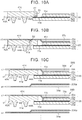
- FIG. 9 is a flowchart that shows the manufacturing method according to the alternative embodiment for the fuel cell 1 A.
- FIG. 10A to FIG. 10C are views that illustrate the manufacturing method according to the alternative embodiment for the fuel cell 1 A.
- the manufacturing method according to the alternative embodiment for the fuel cell 1 A is a method similar to the above-described manufacturing method for the fuel cell 1 . Initially, the MEGA 20 , the support frame 40 A and the first separator 33 c are prepared (step S 10 B). Subsequently, as shown in FIG.
- step S 10A as in the case of the above-described embodiment, the MEGA 20 and the support frame 40 A are bonded to each other by the UV adhesive B 1 (step S 20 B).
- step S 20 B the UV adhesive B 1
- step S 30 B the support frame 40 A and the first separator 33 c are bonded to each other by the UV adhesive B 2 (step S 30 B).
- step S 40 B a plurality of assemblies 59 B, in which the MEGA 20 , the support frame 40 A and the first separator 33 c are bonded to each other, and the plurality of second separators 33 Aa are prepared.
- step S 40 B a plurality of assemblies 59 B, in which the MEGA 20 , the support frame 40 A and the first separator 33 c are bonded to each other, and the plurality of second separators 33 Aa are prepared.
- the assemblies 59 B and the second separators 33 Aa are alternately stacked on top of each other (step S 50 B). Specifically, the plurality of assemblies 59 B and the plurality of second separators 33 Aa are stacked such that the protrusions 43 , 44 A are compressed by the adjacent second separator 33 Aa.
- a gasket (not shown) is arranged between the first separator 33 c and the second separator 33 Aa. When the gasket is compressed, similar portions to those of the above-described laser welding are sealed. Subsequently, as in the case of the above-described embodiment, the plurality of assemblies 59 B and the plurality of second separators 33 Aa, stacked on top of each other, are fastened (step S 60 B).
- the support frame 40 A and the first separator 33 c are bonded to each other without interference of the second separator 33 Aa. Since the MEGA 20 , the support frame 40 A and the first separator 33 c are bonded to each other by the UV adhesive B 1 and the UV adhesive B 2 , an extension of manufacturing time and an increase in manufacturing cost are suppressed. Since the first separator 33 c and the second separator 33 Aa do not need to be welded, an extension of manufacturing time and an increase in manufacturing cost are further suppressed.
Abstract
Description
Claims (8)
Applications Claiming Priority (2)
| Application Number | Priority Date | Filing Date | Title |
|---|---|---|---|
| JP2016234472A JP6547729B2 (en) | 2016-12-01 | 2016-12-01 | Fuel cell manufacturing method |
| JP2016-234472 | 2016-12-01 |
Publications (2)
| Publication Number | Publication Date |
|---|---|
| US20180159160A1 US20180159160A1 (en) | 2018-06-07 |
| US10763530B2 true US10763530B2 (en) | 2020-09-01 |
Family
ID=62243483
Family Applications (1)
| Application Number | Title | Priority Date | Filing Date |
|---|---|---|---|
| US15/797,526 Active 2038-02-15 US10763530B2 (en) | 2016-12-01 | 2017-10-30 | Manufacturing method for fuel cell |
Country Status (2)
| Country | Link |
|---|---|
| US (1) | US10763530B2 (en) |
| JP (1) | JP6547729B2 (en) |
Families Citing this family (4)
| Publication number | Priority date | Publication date | Assignee | Title |
|---|---|---|---|---|
| JP7052442B2 (en) * | 2018-03-14 | 2022-04-12 | トヨタ自動車株式会社 | How to make a fuel cell stack |
| JP7052483B2 (en) * | 2018-03-29 | 2022-04-12 | トヨタ自動車株式会社 | Manufacturing method of integrated sheet |
| DE102019006820A1 (en) | 2019-09-30 | 2021-04-01 | Daimler Ag | Method for bonding components of a fuel cell |
| CN114784313A (en) * | 2022-03-25 | 2022-07-22 | 上海治臻新能源股份有限公司 | Supporting structure for improving deformation of membrane electrode frame of gas cavity of fuel cell |
Citations (14)
| Publication number | Priority date | Publication date | Assignee | Title |
|---|---|---|---|---|
| US20040028983A1 (en) * | 2002-07-19 | 2004-02-12 | Tomokazu Hayashi | Seal structure of fuel cell unit and manufacturing method of the same |
| US20060110651A1 (en) * | 2004-11-25 | 2006-05-25 | Honda Motor Co., Ltd. | Fuel cell |
| JP2007324122A (en) | 2006-05-01 | 2007-12-13 | Honda Motor Co Ltd | Fuel cell |
| JP2008293896A (en) | 2007-05-28 | 2008-12-04 | Toyota Motor Corp | Fuel cell |
| US20090004539A1 (en) * | 2007-06-28 | 2009-01-01 | Honda Motor Co., Ltd. | Fuel cell |
| US20090075134A1 (en) * | 2006-05-01 | 2009-03-19 | Honda Motor Co., Ltd. | Fuel cell |
| US20100216048A1 (en) * | 2006-10-02 | 2010-08-26 | Basf Se | Method for the production of a membrane electrode unit |
| JP2010212001A (en) | 2009-03-09 | 2010-09-24 | Toyota Motor Corp | Method of manufacturing fuel battery cell, device of manufacturing fuel battery cell, and fuel battery |
| US20120178011A1 (en) * | 2011-01-12 | 2012-07-12 | Honda Motor Co., Ltd. | Fuel cell |
| US20140004442A1 (en) * | 2012-06-29 | 2014-01-02 | Honda Motor Co., Ltd. | Fuel cell membrane electrode assembly |
| JP2015115131A (en) * | 2013-12-10 | 2015-06-22 | トヨタ自動車株式会社 | Power generation body |
| JP2016162650A (en) | 2015-03-03 | 2016-09-05 | トヨタ自動車株式会社 | Method for manufacturing fuel battery single cell |
| US20160293976A1 (en) * | 2013-12-27 | 2016-10-06 | Toyota Jidosha Kabushiki Kaisha | Manufacturing method and manufacturing apparatus of electrode frame assembly for fuel cell (as amended) |
| US20180178441A1 (en) * | 2015-06-29 | 2018-06-28 | Nok Corporation | Method of manufacturing gasket |
Family Cites Families (7)
| Publication number | Priority date | Publication date | Assignee | Title |
|---|---|---|---|---|
| US20080289755A1 (en) * | 2006-01-17 | 2008-11-27 | Matthew Peter Burdzy | Bonded Fuel Cell Assembly and Methods and Systems for Producing the Same |
| JP2008041448A (en) * | 2006-08-07 | 2008-02-21 | Nissan Motor Co Ltd | Fuel cell separator, fuel cell, and manufacturing method of the fuel cell |
| JP2010015939A (en) * | 2008-07-07 | 2010-01-21 | Toyota Motor Corp | Fuel cell |
| EP2631976B1 (en) * | 2010-10-20 | 2016-05-25 | Honda Motor Co., Ltd. | Fuel cell |
| CA2920772C (en) * | 2013-08-08 | 2018-04-17 | Nissan Motor Co., Ltd. | Membrane electrode assembly with frame, fuel cell single cell, and fuel cell stack |
| JP6079741B2 (en) * | 2014-10-08 | 2017-02-15 | トヨタ自動車株式会社 | Method for producing a single fuel cell |
| JP2016126911A (en) * | 2014-12-26 | 2016-07-11 | トヨタ自動車株式会社 | Fuel battery single cell |
-
2016
- 2016-12-01 JP JP2016234472A patent/JP6547729B2/en active Active
-
2017
- 2017-10-30 US US15/797,526 patent/US10763530B2/en active Active
Patent Citations (15)
| Publication number | Priority date | Publication date | Assignee | Title |
|---|---|---|---|---|
| US20040028983A1 (en) * | 2002-07-19 | 2004-02-12 | Tomokazu Hayashi | Seal structure of fuel cell unit and manufacturing method of the same |
| US20060110651A1 (en) * | 2004-11-25 | 2006-05-25 | Honda Motor Co., Ltd. | Fuel cell |
| US20090075134A1 (en) * | 2006-05-01 | 2009-03-19 | Honda Motor Co., Ltd. | Fuel cell |
| JP2007324122A (en) | 2006-05-01 | 2007-12-13 | Honda Motor Co Ltd | Fuel cell |
| US20100216048A1 (en) * | 2006-10-02 | 2010-08-26 | Basf Se | Method for the production of a membrane electrode unit |
| JP2008293896A (en) | 2007-05-28 | 2008-12-04 | Toyota Motor Corp | Fuel cell |
| US20090004539A1 (en) * | 2007-06-28 | 2009-01-01 | Honda Motor Co., Ltd. | Fuel cell |
| JP2010212001A (en) | 2009-03-09 | 2010-09-24 | Toyota Motor Corp | Method of manufacturing fuel battery cell, device of manufacturing fuel battery cell, and fuel battery |
| US20120178011A1 (en) * | 2011-01-12 | 2012-07-12 | Honda Motor Co., Ltd. | Fuel cell |
| US20140004442A1 (en) * | 2012-06-29 | 2014-01-02 | Honda Motor Co., Ltd. | Fuel cell membrane electrode assembly |
| JP2015115131A (en) * | 2013-12-10 | 2015-06-22 | トヨタ自動車株式会社 | Power generation body |
| US20160285119A1 (en) * | 2013-12-10 | 2016-09-29 | Toyota Jidosha Kabushiki Kaisha | Power generation body (as amended) |
| US20160293976A1 (en) * | 2013-12-27 | 2016-10-06 | Toyota Jidosha Kabushiki Kaisha | Manufacturing method and manufacturing apparatus of electrode frame assembly for fuel cell (as amended) |
| JP2016162650A (en) | 2015-03-03 | 2016-09-05 | トヨタ自動車株式会社 | Method for manufacturing fuel battery single cell |
| US20180178441A1 (en) * | 2015-06-29 | 2018-06-28 | Nok Corporation | Method of manufacturing gasket |
Non-Patent Citations (1)
| Title |
|---|
| U.S. Appl. No. 15/837,687, filed Dec. 11, 2017, 26 pages. |
Also Published As
| Publication number | Publication date |
|---|---|
| JP2018092773A (en) | 2018-06-14 |
| US20180159160A1 (en) | 2018-06-07 |
| JP6547729B2 (en) | 2019-07-24 |
Similar Documents
| Publication | Publication Date | Title |
|---|---|---|
| JP6104050B2 (en) | Electrolyte membrane / electrode structure for fuel cells | |
| US10270107B2 (en) | Fuel cell and manufacturing method for fuel cell | |
| JP6245194B2 (en) | FUEL CELL SINGLE CELL AND METHOD FOR PRODUCING FUEL CELL SINGLE CELL | |
| JP6237675B2 (en) | FUEL CELL SINGLE CELL AND METHOD FOR PRODUCING FUEL CELL SINGLE CELL | |
| US10763530B2 (en) | Manufacturing method for fuel cell | |
| JP5683433B2 (en) | Fuel cell stack | |
| US9130206B2 (en) | Method for manufacturing resin-framed membrane electrode assembly for fuel cell | |
| US11038190B2 (en) | Membrane electrode assembly, fuel cell comprising assembly of this type and motor vehicle comprising said fuel cell | |
| JP2017139218A (en) | Method of producing fuel cell stack and method of producing metal separator for fuel cell | |
| CA2910082C (en) | Insulating structure, fuel cell and fuel cell stack | |
| US11056703B2 (en) | Manufacturing method of unit cell of fuel cell | |
| WO2014007182A1 (en) | Fuel cell stack | |
| JP6594809B2 (en) | Step MEA with resin frame for fuel cell and manufacturing method thereof | |
| US20190109336A1 (en) | Manufacturing method of unit cell of fuel cell | |
| JP2008171613A (en) | Fuel cells | |
| JP3712592B2 (en) | Manufacturing method of fuel cell | |
| JP6432398B2 (en) | Fuel cell single cell | |
| JP6939459B2 (en) | Fuel cell cell manufacturing method | |
| US11018363B2 (en) | Fuel cell including frame member | |
| JP7302544B2 (en) | Fuel cell manufacturing method | |
| JP2019087486A (en) | Manufacturing method for fuel cell | |
| JP2017111962A (en) | Step mea with resin frame for fuel cell | |
| JP2021136205A (en) | Manufacturing method of fuel cell | |
| JP2022128036A (en) | Unit cell and manufacturing method for laminate including the same | |
| CN112310432A (en) | Framed membrane-electrode assembly for electrolyte, method for manufacturing framed membrane-electrode assembly, and fuel cell |
Legal Events
| Date | Code | Title | Description |
|---|---|---|---|
| AS | Assignment |
Owner name: TOYOTA JIDOSHA KABUSHIKI KAISHA, JAPAN Free format text: ASSIGNMENT OF ASSIGNORS INTEREST;ASSIGNOR:OKABE, HIROKI;REEL/FRAME:044323/0964 Effective date: 20171006 |
|
| FEPP | Fee payment procedure |
Free format text: ENTITY STATUS SET TO UNDISCOUNTED (ORIGINAL EVENT CODE: BIG.); ENTITY STATUS OF PATENT OWNER: LARGE ENTITY |
|
| STPP | Information on status: patent application and granting procedure in general |
Free format text: DOCKETED NEW CASE - READY FOR EXAMINATION |
|
| STPP | Information on status: patent application and granting procedure in general |
Free format text: NON FINAL ACTION MAILED |
|
| STPP | Information on status: patent application and granting procedure in general |
Free format text: NON FINAL ACTION MAILED |
|
| STPP | Information on status: patent application and granting procedure in general |
Free format text: RESPONSE TO NON-FINAL OFFICE ACTION ENTERED AND FORWARDED TO EXAMINER |
|
| STPP | Information on status: patent application and granting procedure in general |
Free format text: FINAL REJECTION MAILED |
|
| STPP | Information on status: patent application and granting procedure in general |
Free format text: ADVISORY ACTION MAILED |
|
| STPP | Information on status: patent application and granting procedure in general |
Free format text: NOTICE OF ALLOWANCE MAILED -- APPLICATION RECEIVED IN OFFICE OF PUBLICATIONS |
|
| STPP | Information on status: patent application and granting procedure in general |
Free format text: PUBLICATIONS -- ISSUE FEE PAYMENT RECEIVED |
|
| STCF | Information on status: patent grant |
Free format text: PATENTED CASE |
|
| MAFP | Maintenance fee payment |
Free format text: PAYMENT OF MAINTENANCE FEE, 4TH YEAR, LARGE ENTITY (ORIGINAL EVENT CODE: M1551); ENTITY STATUS OF PATENT OWNER: LARGE ENTITY Year of fee payment: 4 |