US8336565B2 - Drawer dishwasher - Google Patents
Drawer dishwasher Download PDFInfo
- Publication number
- US8336565B2 US8336565B2 US12/519,710 US51971007A US8336565B2 US 8336565 B2 US8336565 B2 US 8336565B2 US 51971007 A US51971007 A US 51971007A US 8336565 B2 US8336565 B2 US 8336565B2
- Authority
- US
- United States
- Prior art keywords
- lid
- washing tub
- sealing
- dishwasher
- guide
- Prior art date
- Legal status (The legal status is an assumption and is not a legal conclusion. Google has not performed a legal analysis and makes no representation as to the accuracy of the status listed.)
- Expired - Fee Related, expires
Links
Images


Classifications
-
- A—HUMAN NECESSITIES
- A47—FURNITURE; DOMESTIC ARTICLES OR APPLIANCES; COFFEE MILLS; SPICE MILLS; SUCTION CLEANERS IN GENERAL
- A47L—DOMESTIC WASHING OR CLEANING; SUCTION CLEANERS IN GENERAL
- A47L15/00—Washing or rinsing machines for crockery or tableware
- A47L15/42—Details
-
- A—HUMAN NECESSITIES
- A47—FURNITURE; DOMESTIC ARTICLES OR APPLIANCES; COFFEE MILLS; SPICE MILLS; SUCTION CLEANERS IN GENERAL
- A47L—DOMESTIC WASHING OR CLEANING; SUCTION CLEANERS IN GENERAL
- A47L15/00—Washing or rinsing machines for crockery or tableware
- A47L15/42—Details
- A47L15/4246—Details of the tub
-
- A—HUMAN NECESSITIES
- A47—FURNITURE; DOMESTIC ARTICLES OR APPLIANCES; COFFEE MILLS; SPICE MILLS; SUCTION CLEANERS IN GENERAL
- A47L—DOMESTIC WASHING OR CLEANING; SUCTION CLEANERS IN GENERAL
- A47L15/00—Washing or rinsing machines for crockery or tableware
-
- A—HUMAN NECESSITIES
- A47—FURNITURE; DOMESTIC ARTICLES OR APPLIANCES; COFFEE MILLS; SPICE MILLS; SUCTION CLEANERS IN GENERAL
- A47L—DOMESTIC WASHING OR CLEANING; SUCTION CLEANERS IN GENERAL
- A47L15/00—Washing or rinsing machines for crockery or tableware
- A47L15/0084—Washing or rinsing machines for crockery or tableware of drawer-type
-
- A—HUMAN NECESSITIES
- A47—FURNITURE; DOMESTIC ARTICLES OR APPLIANCES; COFFEE MILLS; SPICE MILLS; SUCTION CLEANERS IN GENERAL
- A47L—DOMESTIC WASHING OR CLEANING; SUCTION CLEANERS IN GENERAL
- A47L15/00—Washing or rinsing machines for crockery or tableware
- A47L15/42—Details
- A47L15/4251—Details of the casing
- A47L15/4257—Details of the loading door
- A47L15/4263—Door sealing arrangements
Definitions
- the present disclosure relates to a drawer dishwasher.
- a drawer dishwasher comprising an extractable washing tub for receiving objects that are to be washed, and a lid, for sealing engagement with the washing tub, the lid is movable between an engagement position, wherein it is in sealing engagement with an upper edge of the washing tub, and an opening position, wherein it is spaced from the upper edge of the washing tub.
- Drawer dishwashers are known from e.g. U.S. Pat. No. 6,460,555B1 and U.S. Pat. No. 6,447,081B1.
- a motor-driven system for sealing the lid towards the washing tub is known from the art. Such a system includes a lot of components and is therefore rather expensive.
- U.S. Pat. No. 6,460,555 shows a prior art drawer dishwasher in which a mechanical system for sealing the lid is described.
- the upper drawer has a lid which moves upwardly and downwardly by means of a spring in response to the opening and closing of the drawer.
- the lower edges of the front wall, the side walls and the rear wall of the lid are all provided with U-shaped slots which are provided with sealing gaskets.
- the sealing gaskets are of great importance, if they are damaged the risk of leakage is immediate.
- an object of the invention is to provide a more simple, robust and reliable sealing arrangement to be used in drawer dishwashers.
- a dishwasher according to the preamble of claim 1 which is characterized in that the sealing device is arranged on a guide rail, said guide rail being stationary arranged relative to a frame, which encloses the washing tub and the lid.
- the sealing device presses the lid against the washing tub, the lid is reliably sealed.
- a sealing arrangement according to the invention there is always a pressure from the lid towards the upper part of the drawer, when the lid is in the engagement position. This results in that it is possible to have a plastic to plastic contact between the lid and the upper edge of the washing tub and by that achieve a reliable sealing.
- a sealing gasket which is arranged on the underside of the lid is compressed just as much each time the lid is moved to the engagement position, and by this is a secure sealing between the lid and the upper edge of the washing tub guaranteed.
- the arrangement according to the invention is rather cheap as well, since it is realized with relatively cheap and uncomplicated components.
- a sealing device as stated in claim 2 - 5 , arranged in a guide rail, comprising: A guide in which the lid is movable between the engagement position and the opening position; a projection protruding from an edge of the lid movable in the guide; and a biasing device arranged for pressing the lid towards the upper edge of the washing tub. A pressure is achieved that presses the lid towards the washing tub in the engagement position.
- each of the two guides comprises at least two guides and at least two biasing devices a well-balanced pressure on four points is provided which results in a very tight and reliable sealing between the lid and the upper edge of the washing tub and even if some component would get stuck or brake in one of the four points, the function of the sealing device is maintained.
- the biasing device is a spring.
- the tension in the spring urges the lid towards the washing tub and presses the lid towards the washing tub.
- a front part of the lid will protrude from the front side of the dishwasher when in the opening position.
- the protruding front part of the lid can serve to protect the counter and/or the wooden doors of the kitchen against stream from the dishwasher drawer.
- the front part preferably protrudes by about 30-40 mm, most preferably 32 mm, when the lid is in the opening position.
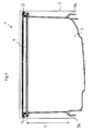
- FIG. 1 schematically illustrates a front view of a drawer dishwasher according to the invention.
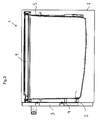
- FIG. 2 schematically illustrates a cross section of a side view of a drawer and a lid when in an engagement position (closed position).
- FIG. 3 schematically illustrates a cross section of a side view of a drawer and a lid when in an opening position.
- FIG. 4 schematically illustrates a cross section of a guide rail comprising a sealing device arranged in the upper part of a frame of the dishwasher drawer and wherein the drawer is loaded with plates.
- FIG. 5 schematically illustrates a detail of the sealing device, when the drawer is in the engagement position (closed position).
- FIG. 6 schematically illustrates a detail of the sealing device, when the drawer is in the opening position.
- FIG. 7 schematically illustrates a detail of the sealing device, when the lid is in the engagement position (closed position).
- FIG. 8 schematically illustrates a detail of the sealing device, when the lid is in the opening position.
- FIG. 9 schematically illustrates a detail of the sealing device comprising a guide and a biasing device when the lid is in a lower position.
- FIG. 10 schematically illustrates a detail of the sealing device comprising a guide and a biasing device when the lid is in an upper position.
- FIG. 11 schematically illustrates a detail of the sealing device comprising a guide and a biasing device when the lid moves between an upper position and a lower position.
- FIGS. 1-3 illustrates a drawer dishwasher 1 , comprising: an extractable washing tub 2 for receiving objects that are to be washed.
- the washing tub 2 comprises a front wall 4 , a rear wall 5 , two side walls and a bottom part.
- the washing tub 2 has a an upper edge 6 .
- the washing tub 2 is preferably made of rigid plastic, or that like.
- the washing tub 2 is extractable relative to a frame 7 of the drawer dishwasher (see FIG. 4 ).
- the washing tub 2 can be arranged in a drawer, but in the following description the washing tub 2 is designed as a drawer so that the washing tub 2 and the drawer are the same unit.
- the washing tub is arranged in the frame 7 , and provided with a front panel 3 .
- the frame 7 refer to the outer part, the cabinet, of the drawer dishwasher, and is designed to fit under a kitchen counter.
- the frame 7 surrounds the washing tub 2 and is preferably made of steel, or that like, but can also be made of other, for the purpose, suitable materials.
- a glide strip 8 a is stationary arranged on the inside of the frame 7 .
- the washing tub 2 which is provided with corresponding strips 8 b , is movable in the glide strip 8 a arranged in the frame 7 , between a closed position and a opened position relative to the frame 7 .
- the drawer dishwasher 1 further comprises a lid 9 , for sealing engagement with the upper edge 6 of the washing tub 2 .
- the lid 9 is movable between an engagement position A (see FIG. 2 ), wherein it is in sealing engagement with the upper edge 6 of the washing tub 2 , and an opening position B (see FIG. 3 ), wherein it is spaced from the upper edge 6 of the washing tub 2 .
- the frame 7 encloses the washing tub 2 and the lid 9 .
- the drawer dishwasher 1 further comprises a sealing device 10 .
- the sealing device 10 is shown in FIG. 4 . Details regarding the sealing device is shown in FIGS. 9-11 .
- the sealing device is arranged to press the lid, when it is in the engagement position A, towards the upper edge 6 of the washing tub 2 .
- press is meant “to exert a force on the lid, the force being directed substantially vertically from the lid, towards the upper edge of the washing tub”.
- the sealing device 10 comprises a guide 12 and a biasing device 14 .
- the sealing device 10 has a stamped portion, preferably made of steel or rigid plastic, to which the guide 12 and the biasing device 14 are attached.
- the sealing device 10 is arranged on a guide rail 11 .
- Two guide rails 11 are stationary arranged, in the upper part, on opposite sides of the inside of the frame 7 .
- the guide 12 has a curved form and extends from a front end 12 a towards a rear end 12 b .
- the front end 12 a is in a laterally higher position, closer to the lid 9 , than the rear end 12 b .
- the guide 12 is preferably made of rigid plastic or that like.
- the lid 9 is provided with a protruding projection 13 .
- the projection 13 is protruding from an edge of the lid 9 .
- the protruding projection 13 is movable in the guide 12 .
- the protruding projection 13 can by way of example be a wheel. By this arrangement the lid 9 is movable in the guide 12 between said engagement position A and said opening position B.
- the biasing device 14 of the sealing device 10 is arranged for pressing the lid towards the upper edge 6 of the washing tub 2 in the engagement position A.
- the biasing device 14 is a spring.
- the spring is arranged under the guide 12 , with one end in connection to the front end 12 a of the guide 12 and one end in connection to the rear end 12 b of the guide 12 .
- the biasing device 14 is movable relative to the guide 12 .
- the sealing device 10 is rotatable about an axle 15 .
- the sealing device 10 is further attached to the guide rail 11 by the axle 15 .
- the axle 15 can for example be a rivet or that like.
- the distance D between the glide strip 8 a and the guide rail 11 is about 230-245 mm.
- the washing tub 2 is movable between a closed position (see FIGS. 2 and 5 ) and a opening position (see FIGS. 3 and 6 ).
- a roof (lid) pusher 20 (see FIG. 5 ), arranged in the rear part of the lid, begins to push the lid 9 from the opening position B towards the engagement position A.
- the tension of the sealing device 10 helps the lid 9 from the engagement position A towards the opening position B.
- the lid When the lid is in the engagement position A, the projection 13 is in the rear end position 12 b of the guide 12 and when the lid 9 is in the opening position B, the projection is in the front end 12 a position of the guide 12 .
- the lid 9 When the lid 9 is in the opening position B, about 20-40 mm of the front part of the lid is viewed outside the frame 7 of the dishwasher 1 , preferably about 32 mm.
- the lid can serve to protect the counter and/or the wooden doors of the kitchen against stream from the dishwasher, when the dishwasher is in position under a kitchen counter (not shown).
- FIG. 9 illustrates the sealing device 10 when the lid is in the engagement position A.
- FIG. 10 illustrates the sealing device 10 when it has adjusted for the tolerances it can adjust for at most. Due to the placement of the spring 14 the added force that is needed to seal the lid 9 towards the upper edge 6 of the washing tub 2 is only 27% (about 75N). Due to the arrangement a deviation of about 8 mm between the lid 9 and the washing tub 2 can be adjusted for and a secure sealing can still be achieved.
- FIG. 11 illustrates the different between the position of the guide 12 and the spring 14 in FIG. 9 and FIG. 10 .
- the lid 9 moves up from the edge 6 of the washing tub 2 and out in the direction from the rear wall 5 of the washing tub 2 towards the front wall 4 of the washing tub 2 .
- the lid 9 is in the engagement position A and a contact surface 21 between the lid 9 and the upper edge 6 of the washing tub 2 is achieved.
- the material of which the lid and the washing tub are made of, for example some kind of hard, plastic material gets in direct contact with each other. It is possible to provide a secure sealing according to the description above because of the design of the sealing device 10 .
- a sealing gasket 22 is arranged underneath the lid as a precaution to avoid the risk of leakage.
- the sealing gasket 22 has low force of compression and is preferably made of extruded, thin-walled silicone rubber, but can also be made of other, for the purpose, suitable materials. By achieving the platic-to-plastic contact it is guaranteed that the sealing gasket 22 is compressed just as much each time the lid 9 is moved to the engagement position A, and by this is a secure sealing between the lid and the upper edge of the washing tub guaranteed.
- the gasket 22 is arranged on the outside of the contact surface 21 .
- the arrangement comprises a spring 16 , which is vertically arranged in the lower part of the frame 7 .
- the spring 16 is attached to a wire 17 , which extends vertically from the spring 16 towards the guide rail 11 .
- a “breaking wheel” 18 is arranged on the guide rail 11 .
- the wire 17 turns around the wheel 18 and continues in a horizontal direction towards the rear part of the guide rail 11 .
- the wire is attached to a control element 19 .
- Two control elements 19 are attached to the lid, see FIG. 4 . They are arranged to regulate the movement of the lid 9 laterally.
- control elements 19 consists of pieces of metal. Four elements 19 are arranged on opposite sides, two on each side, of the lid 9 , see FIG. 4 .
Landscapes
- Washing And Drying Of Tableware (AREA)
- Drawers Of Furniture (AREA)
Applications Claiming Priority (4)
| Application Number | Priority Date | Filing Date | Title |
|---|---|---|---|
| EP06025208 | 2006-12-06 | ||
| EP06025208.7 | 2006-12-06 | ||
| EP06025208A EP1929923B1 (fr) | 2006-12-06 | 2006-12-06 | Lave-vaisselle |
| PCT/EP2007/009801 WO2008067894A1 (fr) | 2006-12-06 | 2007-11-13 | Lave-vaisselle à tiroir |
Publications (2)
| Publication Number | Publication Date |
|---|---|
| US20100083992A1 US20100083992A1 (en) | 2010-04-08 |
| US8336565B2 true US8336565B2 (en) | 2012-12-25 |
Family
ID=38006799
Family Applications (1)
| Application Number | Title | Priority Date | Filing Date |
|---|---|---|---|
| US12/519,710 Expired - Fee Related US8336565B2 (en) | 2006-12-06 | 2007-11-13 | Drawer dishwasher |
Country Status (11)
| Country | Link |
|---|---|
| US (1) | US8336565B2 (fr) |
| EP (1) | EP1929923B1 (fr) |
| KR (1) | KR101464393B1 (fr) |
| CN (1) | CN101568290B (fr) |
| AT (1) | ATE479380T1 (fr) |
| AU (1) | AU2007327945B2 (fr) |
| CA (1) | CA2670665C (fr) |
| DE (1) | DE602006016624D1 (fr) |
| PL (1) | PL1929923T3 (fr) |
| RU (1) | RU2432109C2 (fr) |
| WO (1) | WO2008067894A1 (fr) |
Families Citing this family (8)
| Publication number | Priority date | Publication date | Assignee | Title |
|---|---|---|---|---|
| KR101742991B1 (ko) * | 2009-05-11 | 2017-06-02 | 엘지전자 주식회사 | 세탁장치 |
| JP5445366B2 (ja) * | 2010-07-12 | 2014-03-19 | パナソニック株式会社 | 食器洗い機 |
| US8632144B2 (en) * | 2012-01-28 | 2014-01-21 | Alexandru Nistor | Food storage drawer and container |
| US20130300276A1 (en) * | 2012-05-08 | 2013-11-14 | General Electric Company | Drawer assembly for a refrigerator appliance |
| CN109864680B (zh) * | 2017-12-04 | 2021-09-17 | 青岛海尔洗碗机有限公司 | 一种抽屉式洗碗机 |
| CN109864685B (zh) * | 2017-12-04 | 2022-01-28 | 青岛海尔洗碗机有限公司 | 一种抽屉式洗碗机及控制方法 |
| CN107960965B (zh) * | 2017-12-13 | 2020-11-24 | 佛山市顺德区美的洗涤电器制造有限公司 | 抽屉式洗碗机 |
| CN108201432B (zh) * | 2018-03-09 | 2024-05-10 | 芜湖广盈实业有限公司 | 抽屉式洗碗机的抽屉装置 |
Citations (17)
| Publication number | Priority date | Publication date | Assignee | Title |
|---|---|---|---|---|
| US2654386A (en) * | 1952-05-09 | 1953-10-06 | Gen Electric | Undercounter washing machine |
| US2661750A (en) * | 1951-05-26 | 1953-12-08 | Gen Electric | Under-counter dishwasher |
| US2668091A (en) * | 1949-09-30 | 1954-02-02 | Westinghouse Electric Corp | Washing apparatus |
| US2846286A (en) * | 1954-03-29 | 1958-08-05 | Mc Graw Edison Co | Removable drawer cover |
| US3272580A (en) * | 1964-08-26 | 1966-09-13 | Sperry Rand Corp | Article storage equipment |
| WO1993012706A1 (fr) | 1991-12-20 | 1993-07-08 | Fisher & Paykel Limited | Lave-vaisselle |
| JP2002051959A (ja) * | 2000-08-08 | 2002-02-19 | Rinnai Corp | 引き出し式食器洗浄機 |
| US6447081B1 (en) | 1997-01-30 | 2002-09-10 | Fisher & Paykel Limited | Dishwasher |
| US6460555B1 (en) | 1998-09-21 | 2002-10-08 | Maytag Corporation | Dual dishwasher construction |
| JP2002360495A (ja) * | 2001-06-07 | 2002-12-17 | Rinnai Corp | 引出し式食器洗浄機 |
| JP2004261259A (ja) * | 2003-02-28 | 2004-09-24 | Mitsubishi Electric Corp | 食器洗浄機 |
| WO2006057567A1 (fr) | 2004-11-24 | 2006-06-01 | Fisher & Paykel Appliances Limited | Joint pour couvercle de lave-vaisselle coulissant |
| EP1700558A2 (fr) | 1999-10-08 | 2006-09-13 | Fisher & Paykel Appliances Ltd. | Lave-vaiselle |
| US20060213909A1 (en) * | 2005-03-23 | 2006-09-28 | Epp Richard J | Top closure member for a storage bin |
| US7345264B2 (en) * | 2005-02-15 | 2008-03-18 | Sharp Kabushiki Kaisha | Built-in kitchen apparatus |
| US7624745B2 (en) * | 2006-04-20 | 2009-12-01 | Maytag Corporation | Drawer-type dishwasher having modular support body |
| US7731804B2 (en) * | 2006-08-09 | 2010-06-08 | Maytag Corporation | Lid operating mechanism for a drawer-type dishwasher |
Family Cites Families (2)
| Publication number | Priority date | Publication date | Assignee | Title |
|---|---|---|---|---|
| JP3095002B2 (ja) * | 1998-12-02 | 2000-10-03 | 松下電器産業株式会社 | 食器洗浄機 |
| CN2530585Y (zh) * | 2002-02-09 | 2003-01-15 | 无锡小天鹅梅洛尼洗碗机有限公司 | 洗碗机密封装置 |
-
2006
- 2006-12-06 EP EP06025208A patent/EP1929923B1/fr not_active Not-in-force
- 2006-12-06 AT AT06025208T patent/ATE479380T1/de not_active IP Right Cessation
- 2006-12-06 DE DE602006016624T patent/DE602006016624D1/de active Active
- 2006-12-06 PL PL06025208T patent/PL1929923T3/pl unknown
-
2007
- 2007-11-13 WO PCT/EP2007/009801 patent/WO2008067894A1/fr active Application Filing
- 2007-11-13 CN CN2007800448177A patent/CN101568290B/zh not_active Expired - Fee Related
- 2007-11-13 AU AU2007327945A patent/AU2007327945B2/en not_active Ceased
- 2007-11-13 CA CA2670665A patent/CA2670665C/fr not_active Expired - Fee Related
- 2007-11-13 KR KR1020097013132A patent/KR101464393B1/ko not_active IP Right Cessation
- 2007-11-13 US US12/519,710 patent/US8336565B2/en not_active Expired - Fee Related
- 2007-11-13 RU RU2009125555/12A patent/RU2432109C2/ru not_active IP Right Cessation
Patent Citations (18)
| Publication number | Priority date | Publication date | Assignee | Title |
|---|---|---|---|---|
| US2668091A (en) * | 1949-09-30 | 1954-02-02 | Westinghouse Electric Corp | Washing apparatus |
| US2661750A (en) * | 1951-05-26 | 1953-12-08 | Gen Electric | Under-counter dishwasher |
| US2654386A (en) * | 1952-05-09 | 1953-10-06 | Gen Electric | Undercounter washing machine |
| US2846286A (en) * | 1954-03-29 | 1958-08-05 | Mc Graw Edison Co | Removable drawer cover |
| US3272580A (en) * | 1964-08-26 | 1966-09-13 | Sperry Rand Corp | Article storage equipment |
| WO1993012706A1 (fr) | 1991-12-20 | 1993-07-08 | Fisher & Paykel Limited | Lave-vaisselle |
| US5755244A (en) | 1991-12-20 | 1998-05-26 | Fisher & Paykel Limited | Dishwasher |
| US6447081B1 (en) | 1997-01-30 | 2002-09-10 | Fisher & Paykel Limited | Dishwasher |
| US6460555B1 (en) | 1998-09-21 | 2002-10-08 | Maytag Corporation | Dual dishwasher construction |
| EP1700558A2 (fr) | 1999-10-08 | 2006-09-13 | Fisher & Paykel Appliances Ltd. | Lave-vaiselle |
| JP2002051959A (ja) * | 2000-08-08 | 2002-02-19 | Rinnai Corp | 引き出し式食器洗浄機 |
| JP2002360495A (ja) * | 2001-06-07 | 2002-12-17 | Rinnai Corp | 引出し式食器洗浄機 |
| JP2004261259A (ja) * | 2003-02-28 | 2004-09-24 | Mitsubishi Electric Corp | 食器洗浄機 |
| WO2006057567A1 (fr) | 2004-11-24 | 2006-06-01 | Fisher & Paykel Appliances Limited | Joint pour couvercle de lave-vaisselle coulissant |
| US7345264B2 (en) * | 2005-02-15 | 2008-03-18 | Sharp Kabushiki Kaisha | Built-in kitchen apparatus |
| US20060213909A1 (en) * | 2005-03-23 | 2006-09-28 | Epp Richard J | Top closure member for a storage bin |
| US7624745B2 (en) * | 2006-04-20 | 2009-12-01 | Maytag Corporation | Drawer-type dishwasher having modular support body |
| US7731804B2 (en) * | 2006-08-09 | 2010-06-08 | Maytag Corporation | Lid operating mechanism for a drawer-type dishwasher |
Non-Patent Citations (1)
| Title |
|---|
| International Search Report for PCT/EP2007/009801, dated Apr. 17, 2008, 3 pages. |
Also Published As
| Publication number | Publication date |
|---|---|
| EP1929923B1 (fr) | 2010-09-01 |
| CA2670665C (fr) | 2015-01-27 |
| ATE479380T1 (de) | 2010-09-15 |
| CA2670665A1 (fr) | 2008-06-12 |
| RU2432109C2 (ru) | 2011-10-27 |
| CN101568290A (zh) | 2009-10-28 |
| AU2007327945A1 (en) | 2008-06-12 |
| RU2009125555A (ru) | 2011-01-20 |
| EP1929923A1 (fr) | 2008-06-11 |
| PL1929923T3 (pl) | 2011-04-29 |
| CN101568290B (zh) | 2012-08-22 |
| AU2007327945B2 (en) | 2012-08-02 |
| KR20090091313A (ko) | 2009-08-27 |
| KR101464393B1 (ko) | 2014-12-04 |
| DE602006016624D1 (de) | 2010-10-14 |
| US20100083992A1 (en) | 2010-04-08 |
| WO2008067894A1 (fr) | 2008-06-12 |
Similar Documents
| Publication | Publication Date | Title |
|---|---|---|
| US8336565B2 (en) | Drawer dishwasher | |
| US20180320437A1 (en) | Sealing unit for a sliding door | |
| DE60032252T2 (de) | Geschirrspülmaschine | |
| JPH0326004B2 (fr) | ||
| KR20170119212A (ko) | 슬라이딩 도어용 롤러 브라켓 | |
| KR100688689B1 (ko) | 식기 세정기 | |
| CN108903884A (zh) | 一种洗碗机的盖板运动结构 | |
| KR200419186Y1 (ko) | 붙박이장용 가이드레일 및 롤러의 구조 | |
| KR101108332B1 (ko) | 서랍식 냉장고 | |
| CN211243242U (zh) | 一种洗碗机 | |
| EP3409824A1 (fr) | Appareil de lavage à porte coulissante dotée d'un dispositif permettant de recueillir et d'évacuer l'eau gouttant de la porte | |
| KR20150002556U (ko) | 방풍 및 방음용 패킹부재 | |
| US9278803B2 (en) | Receptacle | |
| CN209474538U (zh) | 一种洗碗机的密封结构 | |
| CN109186169B (zh) | 一种冰箱密封门的防漏冷密封结构 | |
| CN211534323U (zh) | 一种洗碗机门的密封结构 | |
| CN201110073Y (zh) | 一种柜门用tt型铰链 | |
| CN111648705A (zh) | 一种密封涨紧隔离门板机构及用于磁粉成型压机的隔离门装置 | |
| KR102401321B1 (ko) | 오토드롭씰 | |
| CN220415164U (zh) | 一种用于湿法烟气脱硫设备的插板门 | |
| CN215909124U (zh) | 烹饪器具的门封和具有其的烹饪器具 | |
| CN208973714U (zh) | 一种洗碗机用门下密封组件结构 | |
| CN217146815U (zh) | 一种具有防尘隔温的包装盒 | |
| KR200320253Y1 (ko) | 씽크대 하부서랍의 개폐장치 | |
| CN205429489U (zh) | 一种用于开关箱面板的卡件 |
Legal Events
| Date | Code | Title | Description |
|---|---|---|---|
| AS | Assignment |
Owner name: ELECTROLUX HOME PRODUCTS CORPORATION N.V.,BELGIUM Free format text: ASSIGNMENT OF ASSIGNORS INTEREST;ASSIGNORS:WRANGBERTH, STELLAN;HAGELIN, ARNE;SVENSSON, MATS;SIGNING DATES FROM 20090629 TO 20090912;REEL/FRAME:023612/0270 Owner name: ELECTROLUX HOME PRODUCTS CORPORATION N.V., BELGIUM Free format text: ASSIGNMENT OF ASSIGNORS INTEREST;ASSIGNORS:WRANGBERTH, STELLAN;HAGELIN, ARNE;SVENSSON, MATS;SIGNING DATES FROM 20090629 TO 20090912;REEL/FRAME:023612/0270 |
|
| FEPP | Fee payment procedure |
Free format text: PAYOR NUMBER ASSIGNED (ORIGINAL EVENT CODE: ASPN); ENTITY STATUS OF PATENT OWNER: LARGE ENTITY |
|
| STCF | Information on status: patent grant |
Free format text: PATENTED CASE |
|
| FPAY | Fee payment |
Year of fee payment: 4 |
|
| FEPP | Fee payment procedure |
Free format text: MAINTENANCE FEE REMINDER MAILED (ORIGINAL EVENT CODE: REM.); ENTITY STATUS OF PATENT OWNER: LARGE ENTITY |
|
| LAPS | Lapse for failure to pay maintenance fees |
Free format text: PATENT EXPIRED FOR FAILURE TO PAY MAINTENANCE FEES (ORIGINAL EVENT CODE: EXP.); ENTITY STATUS OF PATENT OWNER: LARGE ENTITY |
|
| STCH | Information on status: patent discontinuation |
Free format text: PATENT EXPIRED DUE TO NONPAYMENT OF MAINTENANCE FEES UNDER 37 CFR 1.362 |
|
| FP | Lapsed due to failure to pay maintenance fee |
Effective date: 20201225 |