US8310409B2 - Display device and display method - Google Patents
Display device and display method Download PDFInfo
- Publication number
- US8310409B2 US8310409B2 US10/485,635 US48563504A US8310409B2 US 8310409 B2 US8310409 B2 US 8310409B2 US 48563504 A US48563504 A US 48563504A US 8310409 B2 US8310409 B2 US 8310409B2
- Authority
- US
- United States
- Prior art keywords
- light rays
- light
- screen
- image
- images
- Prior art date
- Legal status (The legal status is an assumption and is not a legal conclusion. Google has not performed a legal analysis and makes no representation as to the accuracy of the status listed.)
- Expired - Fee Related, expires
Links
Images


Classifications
-
- G—PHYSICS
- G02—OPTICS
- G02B—OPTICAL ELEMENTS, SYSTEMS OR APPARATUS
- G02B27/00—Optical systems or apparatus not provided for by any of the groups G02B1/00 - G02B26/00, G02B30/00
- G02B27/02—Viewing or reading apparatus
- G02B27/06—Viewing or reading apparatus with moving picture effect
-
- G—PHYSICS
- G03—PHOTOGRAPHY; CINEMATOGRAPHY; ANALOGOUS TECHNIQUES USING WAVES OTHER THAN OPTICAL WAVES; ELECTROGRAPHY; HOLOGRAPHY
- G03B—APPARATUS OR ARRANGEMENTS FOR TAKING PHOTOGRAPHS OR FOR PROJECTING OR VIEWING THEM; APPARATUS OR ARRANGEMENTS EMPLOYING ANALOGOUS TECHNIQUES USING WAVES OTHER THAN OPTICAL WAVES; ACCESSORIES THEREFOR
- G03B21/00—Projectors or projection-type viewers; Accessories therefor
-
- G—PHYSICS
- G02—OPTICS
- G02B—OPTICAL ELEMENTS, SYSTEMS OR APPARATUS
- G02B30/00—Optical systems or apparatus for producing three-dimensional [3D] effects, e.g. stereoscopic images
- G02B30/20—Optical systems or apparatus for producing three-dimensional [3D] effects, e.g. stereoscopic images by providing first and second parallax images to an observer's left and right eyes
- G02B30/34—Stereoscopes providing a stereoscopic pair of separated images corresponding to parallactically displaced views of the same object, e.g. 3D slide viewers
- G02B30/35—Stereoscopes providing a stereoscopic pair of separated images corresponding to parallactically displaced views of the same object, e.g. 3D slide viewers using reflective optical elements in the optical path between the images and the observer
-
- G—PHYSICS
- G02—OPTICS
- G02B—OPTICAL ELEMENTS, SYSTEMS OR APPARATUS
- G02B30/00—Optical systems or apparatus for producing three-dimensional [3D] effects, e.g. stereoscopic images
- G02B30/50—Optical systems or apparatus for producing three-dimensional [3D] effects, e.g. stereoscopic images the image being built up from image elements distributed over a 3D volume, e.g. voxels
- G02B30/54—Optical systems or apparatus for producing three-dimensional [3D] effects, e.g. stereoscopic images the image being built up from image elements distributed over a 3D volume, e.g. voxels the 3D volume being generated by moving a 2D surface, e.g. by vibrating or rotating the 2D surface
-
- G—PHYSICS
- G03—PHOTOGRAPHY; CINEMATOGRAPHY; ANALOGOUS TECHNIQUES USING WAVES OTHER THAN OPTICAL WAVES; ELECTROGRAPHY; HOLOGRAPHY
- G03B—APPARATUS OR ARRANGEMENTS FOR TAKING PHOTOGRAPHS OR FOR PROJECTING OR VIEWING THEM; APPARATUS OR ARRANGEMENTS EMPLOYING ANALOGOUS TECHNIQUES USING WAVES OTHER THAN OPTICAL WAVES; ACCESSORIES THEREFOR
- G03B21/00—Projectors or projection-type viewers; Accessories therefor
- G03B21/14—Details
- G03B21/28—Reflectors in projection beam
-
- G—PHYSICS
- G03—PHOTOGRAPHY; CINEMATOGRAPHY; ANALOGOUS TECHNIQUES USING WAVES OTHER THAN OPTICAL WAVES; ELECTROGRAPHY; HOLOGRAPHY
- G03B—APPARATUS OR ARRANGEMENTS FOR TAKING PHOTOGRAPHS OR FOR PROJECTING OR VIEWING THEM; APPARATUS OR ARRANGEMENTS EMPLOYING ANALOGOUS TECHNIQUES USING WAVES OTHER THAN OPTICAL WAVES; ACCESSORIES THEREFOR
- G03B21/00—Projectors or projection-type viewers; Accessories therefor
- G03B21/54—Accessories
- G03B21/56—Projection screens
- G03B21/562—Screens moving during projection
-
- G—PHYSICS
- G03—PHOTOGRAPHY; CINEMATOGRAPHY; ANALOGOUS TECHNIQUES USING WAVES OTHER THAN OPTICAL WAVES; ELECTROGRAPHY; HOLOGRAPHY
- G03B—APPARATUS OR ARRANGEMENTS FOR TAKING PHOTOGRAPHS OR FOR PROJECTING OR VIEWING THEM; APPARATUS OR ARRANGEMENTS EMPLOYING ANALOGOUS TECHNIQUES USING WAVES OTHER THAN OPTICAL WAVES; ACCESSORIES THEREFOR
- G03B21/00—Projectors or projection-type viewers; Accessories therefor
- G03B21/54—Accessories
- G03B21/56—Projection screens
- G03B21/60—Projection screens characterised by the nature of the surface
- G03B21/606—Projection screens characterised by the nature of the surface for relief projection
-
- G—PHYSICS
- G03—PHOTOGRAPHY; CINEMATOGRAPHY; ANALOGOUS TECHNIQUES USING WAVES OTHER THAN OPTICAL WAVES; ELECTROGRAPHY; HOLOGRAPHY
- G03B—APPARATUS OR ARRANGEMENTS FOR TAKING PHOTOGRAPHS OR FOR PROJECTING OR VIEWING THEM; APPARATUS OR ARRANGEMENTS EMPLOYING ANALOGOUS TECHNIQUES USING WAVES OTHER THAN OPTICAL WAVES; ACCESSORIES THEREFOR
- G03B21/00—Projectors or projection-type viewers; Accessories therefor
- G03B21/54—Accessories
- G03B21/56—Projection screens
- G03B21/60—Projection screens characterised by the nature of the surface
- G03B21/62—Translucent screens
-
- G—PHYSICS
- G03—PHOTOGRAPHY; CINEMATOGRAPHY; ANALOGOUS TECHNIQUES USING WAVES OTHER THAN OPTICAL WAVES; ELECTROGRAPHY; HOLOGRAPHY
- G03B—APPARATUS OR ARRANGEMENTS FOR TAKING PHOTOGRAPHS OR FOR PROJECTING OR VIEWING THEM; APPARATUS OR ARRANGEMENTS EMPLOYING ANALOGOUS TECHNIQUES USING WAVES OTHER THAN OPTICAL WAVES; ACCESSORIES THEREFOR
- G03B35/00—Stereoscopic photography
- G03B35/18—Stereoscopic photography by simultaneous viewing
- G03B35/20—Stereoscopic photography by simultaneous viewing using two or more projectors
-
- H—ELECTRICITY
- H04—ELECTRIC COMMUNICATION TECHNIQUE
- H04N—PICTORIAL COMMUNICATION, e.g. TELEVISION
- H04N13/00—Stereoscopic video systems; Multi-view video systems; Details thereof
- H04N13/30—Image reproducers
- H04N13/349—Multi-view displays for displaying three or more geometrical viewpoints without viewer tracking
- H04N13/354—Multi-view displays for displaying three or more geometrical viewpoints without viewer tracking for displaying sequentially
-
- H—ELECTRICITY
- H04—ELECTRIC COMMUNICATION TECHNIQUE
- H04N—PICTORIAL COMMUNICATION, e.g. TELEVISION
- H04N9/00—Details of colour television systems
- H04N9/12—Picture reproducers
- H04N9/31—Projection devices for colour picture display, e.g. using electronic spatial light modulators [ESLM]
- H04N9/3141—Constructional details thereof
Definitions
- the present invention relates to display apparatuses and display methods, and particularly, to a display apparatus and a display method that allow multiple users to view high-resolution moving images from the users' individual viewing points.
- IP Integral Photography
- FIG. 1 illustrates an example of the IP 3D-image system.
- a camera (video camera) 202 captures an image of an object through a lens array 201 .
- the lens array 201 has multiple microlenses disposed in a plane.
- the camera 202 captures the image of the object through each of the lenses.
- a display apparatus 203 such as a liquid crystal display, displays the image captured by the camera 202 .
- a lens array 204 is disposed over the front face of a display screen of the display apparatus 203 .
- the lens array 204 has the same structure as the lens array 201 .
- a user sees the image displayed on the display apparatus 203 through the lens array 204 .
- the user is able to view the image of the object of a certain viewing point.
- the image captured by the camera 202 is a combination of image elements (referred to as microlens image-elements hereinafter) of the object seen through the microlenses of the lens array 201 .
- the image displayed on the display apparatus 203 is a combination of the microlens image-elements.
- the combination of the microlens image-elements is viewed from a certain viewing point through the lens array 204 having the same structure as the lens array 201 .
- the image of the object seen from that viewing point is therefore formed of pixels which are formed of the microlens image-elements seen through the microlenses of the lens array 204 .
- the IP 3D-image system presents images that can be viewed from various viewing points of multiple users.
- an image of an object seen from a certain viewing point is formed of pixels that are formed by combining microlens image-elements of the microlenses of the lens array 204 .
- the image resolution presented to a user depends on properties and density of the microlenses of the lens arrays 201 and 204 .
- Another 3D display system that presents images viewable from various viewing points of multiple users is, for example, Zebra Imaging developed by Zebra Imaging, Inc.
- Zebra Imaging uses holography technology to present high-resolution images that can be viewed from various viewing points of multiple users.
- the images displayed using Zebra Imaging are holograms, the production of the images requires many hours for calculation, thus leading to difficulties in displaying moving images.
- the present invention enables multiple users to view high-resolution moving images from various viewing points of the users.
- a first display apparatus of the present invention includes a screen which receives light rays to display images corresponding to the light rays, driving means for rotating the screen around or on a predetermined rotational axis thereof, and irradiating means for irradiating the screen with the light rays corresponding to the images from various directions.
- a first display method of the present invention includes the steps of rotating a screen around or on a predetermined rotational axis thereof such that the screen receives light rays to display images corresponding to the light rays, and irradiating the screen with the light rays corresponding to the images from various directions.
- a second display apparatus of the present invention includes a diffusing plate that receives and diffuses light rays to display images corresponding to the light rays, and at least one optical filter that transmits only a portion of the light rays diffused by the diffusing plate, the portion of the light rays traveling in a predetermined direction.
- a second display method of the present invention includes the steps of displaying images corresponding to light rays that are received and diffused by a diffusing plate for diffusing received light rays, and transmitting only a portion of the light rays diffused by the diffusing plate, the portion of the light rays traveling in a predetermined direction.
- the screen that receives light rays to display images corresponding to the light rays is rotated around or on the predetermined rotational axis of the screen so that the screen is irradiated with the light rays corresponding to the images from various directions.
- the diffusing plate for diffusing received light rays is transmitted to display images corresponding to the light rays, the portion of the light rays traveling in a predetermined direction.
- FIG. 1 illustrates an example of an IP 3D-image system
- FIG. 2A is a plan view of a lens array 201 and a lens array 204 ;
- FIG. 2B is a cross-sectional view of the lens array 201 and the lens array 204 ;
- FIG. 3 illustrates a first embodiment of an image-capturing/display system employing the present invention
- FIG. 4 is a block diagram of an image-capturing apparatus 1 ;
- FIG. 5 illustrates a flow chart describing the operation of the image-capturing apparatus 1 ;
- FIG. 6 is a block diagram of a display apparatus 2 ;
- FIG. 7 is a cross-sectional view of a first configuration of a light-control screen 25 ;
- FIG. 8 is a perspective view of optical filter films 55 and 56 ;
- FIG. 9 illustrates the optical characteristics of the optical filter films 55 and 56 ;
- FIG. 10A is a diagram to describe the image display on an optical display device 20 ;
- FIG. 10B is a diagram to describe the image display on the optical display device 20 ;
- FIG. 11 is a flow chart describing the operation of the display apparatus 2 ;
- FIG. 12 is a cross-sectional view of a second configuration of the light-control screen 25 ;
- FIG. 13 is a cross-sectional view of a third configuration of the light-control screen 25 ;
- FIG. 14A illustrates the positional relationship between projectors 21 n and users
- FIG. 14B illustrates the positional relationship between projectors 21 n and users
- FIG. 15 illustrates an example of the optical display device 20 ;
- FIG. 16 illustrates an optical path of a light ray according to the optical display device 20 ;
- FIG. 17 is a block diagram of an example of a signal processor 22 ;
- FIG. 18 illustrates an equidistant projection fish-eye lens
- FIG. 19 is a diagram illustrating a light ray projected from a fish-eye lens 75 ;
- FIG. 20 is a diagram illustrating the traveling direction of a light ray R represented by angles ⁇ and ⁇ ;
- FIG. 21 is a block diagram of an example of a signal processor 12 ;
- FIG. 22 is a block diagram of another example of the signal processor 22 ;
- FIG. 23 is a block diagram of a second embodiment of the image-capturing/display system employing the present invention.
- FIG. 24 illustrates optical image-capturing devices 10 1 and 10 2 , respectively, capturing images of objects S 1 and S 2 ;
- FIG. 25 illustrates an optical display device 20 displaying a combination of the images of the objects S 1 and S 2 ;
- FIG. 26 is a plan view of another example of the optical display device 20 ;
- FIG. 27 is a block diagram of an embodiment of a computer employing the present invention.
- FIG. 28A illustrates a result of comparing the image-capturing/display system employing the present invention with the IP 3D-image system and Zebra Imaging;
- FIG. 28B illustrates another result of comparing the image-capturing/display system employing the present invention with the IP 3D-image system and Zebra Imaging;
- FIG. 28C illustrates another result of comparing the image-capturing/display system employing the present invention with the IP 3D-image system and Zebra Imaging;
- FIG. 28D illustrates another result of comparing the image-capturing/display system employing the present invention with the IP 3D-image system and Zebra Imaging.
- FIG. 3 illustrates a first embodiment of an image-capturing/display system employing the present invention.
- system is referred to as a product having multiple apparatuses orderly assembled together, meaning that the apparatuses do not necessarily need to be disposed within the same housing.
- the image-capturing/display system includes an image-capturing apparatus 1 and a display apparatus 2 .
- the image-capturing apparatus 1 captures images of an object and transmits the obtained image data via a transmission medium 3 such as terrestrial broadcast waves, a satellite connection, a cable television (CATV) network, a telephone line, and the Internet.
- a transmission medium 3 such as terrestrial broadcast waves, a satellite connection, a cable television (CATV) network, a telephone line, and the Internet.
- the image data may be recorded onto a recording medium 4 such as a semiconductor memory, an optical disc, and a magnetic disc.
- the display apparatus 2 receives the image data sent through the transmission medium 3 or the image data played back from the recording medium 4 to display the image data.
- FIG. 4 illustrates the image-capturing apparatus 1 of FIG. 3 .
- the image-capturing apparatus 1 includes an optical image-capturing device 10 and a signal processor 12 .
- the optical image-capturing device 10 includes N cameras 11 1 to 11 N .
- the N cameras 11 1 to 11 N are disposed at, for example, regular intervals (at equal angles) horizontally around the 360° periphery of the object. Furthermore, the N cameras 11 1 to 11 N are disposed in a state such that optical axes of the cameras, for example, are in the same horizontal plane and converge at one point in that horizontal plane.
- the positioning of the N cameras 11 1 to 11 N is not limited to the description above.
- the N cameras 11 1 to 11 N may be disposed at, for example, uneven intervals.
- Each of the cameras 11 n captures an image of the object.
- each camera 11 n receives light from the object and performs photoelectric conversion so as to obtain image data of the object.
- Each of the obtained image data is supplied to the signal processor 12 in, for example, frame units (or field units).
- the signal processor 12 includes storage 31 1 to 31 N , an encoder 32 , and a multiplexer 33 .
- the number of storages 31 1 to 31 N provided is equal to the number of cameras 11 1 to 11 N .
- the signal processor 12 processes the image data supplied from the cameras 11 n and then outputs the data.
- Each of the storages 31 n temporarily stores the image data supplied from the corresponding one of the cameras 11 n .
- the encoder 32 reads out the image data from each of the storages 31 1 to 31 N and performs compression-encoding on each data by a predetermined process such as a digital video (DV) process.
- the encoder 32 supplies the encoded data obtained by the compression-encoding of the image data to the multiplexer 33 .
- the encoded data which are supplied from the encoder 32 and correspond to the image data captured by each of the N cameras 11 1 to 11 N , are multiplexed to form one data stream by the multiplexer 33 .
- the data stream is then transmitted via the transmission medium 3 (see FIG. 3 ) or is supplied to the recording medium 4 (see FIG. 3 ) to be recorded thereon.
- each camera 11 n captures an image of the object and supplies the obtained image data of one frame to a corresponding storage 31 n of the signal processor 12 .
- Step S 1 then proceeds to step S 2 .
- each storage 31 n stores the image data supplied from the corresponding camera 11 n .
- Step S 2 then proceeds to step S 3 .
- the encoder 32 reads out the image data stored in each storage 31 n and encodes the data. The encoded data obtained are then supplied to the multiplexer 33 .
- step S 4 the encoded data, which are supplied from the encoder 32 and correspond to the image data captured by each of the N cameras 11 1 to 11 N , are multiplexed to form one data stream by the multiplexer 33 .
- the data stream is then output from the multiplexer 33 .
- the data stream output from the multiplexer 33 is transmitted via the transmission medium 3 (see FIG. 3 ) or is supplied to the recording medium 4 (see FIG. 3 ) to be recorded thereon.
- step S 5 it is determined whether an operating unit, which is not shown in the drawings, is operated by a user to terminate the image-capturing of the image data (referred to as image-capture termination hereinafter).
- step S 5 If it is determined that the image-capture termination is not performed in step S 5 , step S 5 then returns to step S 1 so that the same steps are repeated over again.
- step S 5 the operation ends.
- the N cameras 11 1 to 11 N capture images of the object from N viewing points surrounding the object.
- the cameras 11 1 to 11 N capture a series of continuous images as seen horizontally from the 360° periphery of the object.
- FIG. 6 illustrates the display apparatus 2 of FIG. 3 .
- the display apparatus 2 includes an optical display device 20 , a signal processor 22 , and a controller 23 .
- the optical display device 20 includes N projectors 21 1 to 21 N , a driver 24 , and a light-control screen 25 .
- the number of projectors 21 1 to 21 N provided is equal to the number of cameras 11 1 to 11 N of the optical image-capturing device 10 .
- the N projectors 21 1 to 21 N are disposed horizontally around the 360° periphery of the light-control screen 25 .
- the positioning of the N projectors 21 1 to 21 N corresponds to the positioning of the N cameras 11 1 to 11 N of the optical image-capturing device 10 (see FIG. 4 ). From each of the N projectors, light rays of the corresponding image data supplied from the signal processor 22 are emitted. Thus, the light-control screen 25 is irradiated with the light rays.
- the N projectors 21 1 to 21 N are disposed in a state such that the physical relationship of the optical axes of the projectors is similar to that of the N cameras 11 1 to 11 N . Accordingly, as with the N cameras 11 1 to 11 N illustrated in FIG. 4 , the N projectors 21 1 to 21 N are disposed at, for example, regular intervals (at equal angles) around the 360° periphery of the light-control screen 25 . Furthermore, the optical axes of the projectors, for example, are in the same horizontal plane and converge at one point in that horizontal plane.
- the driver 24 is controlled by the controller 23 and accordingly rotates the light-control screen 25 at, for example, a constant rate.
- the light-control screen 25 is, for example, a rectangular screen.
- the light control screen 25 receives light rays emitted from the projectors 21 n and displays images that correspond to the light rays.
- the light-control screen 25 has an axis 25 A extending vertically through the screen 25 to define left and right sides on the screen 25 .
- the axis 25 A functions as a rotational axis for the driver 24 to rotate the light-control screen 25 .
- the N projectors 21 1 to 21 N are disposed in a state such that the optical axes of the projectors, for example, converge at one point on the axis 25 A of the light-control screen 25 .
- the signal processor 22 includes a storage 41 , a demultiplexer 42 , and a decoder 43 .
- the storage 41 temporarily stores a data stream transmitted via the transmission medium 3 (see FIG. 3 ) or played back from the recording medium 4 (see FIG. 3 ).
- the demultiplexer 42 reads out the data stream stored in the storage 41 .
- the demultiplexer 42 then demultiplexes the data stream into each encoded data, that is, each encoded image data originally captured by the corresponding one of the cameras 11 1 to 11 N .
- Each encoded data is then supplied to the decoder 43 .
- the decoder 43 decodes each encoded data supplied from the demultiplexer 42 into image data originally captured by the corresponding one of the cameras 11 1 to 11 N .
- the decoder 43 then supplies the image data originally captured by one of the cameras 11 n to, for example, the corresponding projector 21 n .
- the decoder 43 supplies image data originally captured by one of the cameras 11 n to the corresponding projector 21 n in, for example, frame units. In this case, the supplying of the image data is performed synchronously with the supplying of the image data from the other cameras 11 n to the other corresponding projectors 21 n .
- the controller 23 controls the driver 24 so that the driver 24 rotates the light-control screen 25 in synchronization with the timing of the supplying of the image data from the decoder 43 to the projectors 21 1 to 21 N .
- FIG. 7 is a cross-sectional view of a first configuration of the light-control screen 25 of FIG. 6 .
- the light-control screen 25 includes a double-faced screen component 51 and optical-filter films 55 and 56 .
- the double-faced screen component 51 is formed of flat diffusing plates 52 and 53 and a light-blocking plate 54 .
- the light-blocking plate 54 is disposed between the diffusing plates 52 and 53 (the light-blocking plate 54 is sandwiched between the diffusing plates 52 and 53 ).
- the light-blocking plate 54 is disposed over the diffusing plate 53
- the diffusing plate 52 is disposed over the light-blocking plate 54 .
- the double-faced screen component 51 displays images independently in the two faces, that is, the face adjacent to the diffusing plate 52 and the face adjacent to the diffusing plate 53 .
- the diffusing plates 52 and 53 may be formed of a material that diffuses light, such ground glass.
- the light-control screen 25 has the optical-filter films 55 and 56 respectively disposed over the faces adjacent to the diffusing plates 52 and 53 of the double-faced screen component 51 .
- the optical-filter films 55 and 56 are sheet-like optical filters having a louver-like structure.
- the films 55 and 56 are formed of multiple fine rectangular film components that block light.
- the fine-film components are disposed at short intervals in a state such that the surfaces of the film components face each other. Thus, slits are formed between the fine-film components.
- the optical-filter films 55 and 56 have optical characteristics as shown in the drawing.
- the optical-filter films 55 and 56 have optical characteristics that directly transmit light rays traveling only in the forward direction, while reducing the light intensity of the transmitting light rays deviated from the forward direction (light rays that are incident on the surface of the fine-film components). Accordingly, when the optical-filter film 55 or 56 is viewed in the forward direction, the opposite side is viewable, whereas when the optical-filter film 55 or 56 is viewed in a direction deviated from the forward direction (viewed at an angle), the opposite side cannot be viewed.
- a Light Control Film manufactured by Sumitomo 3M Ltd. may be used.
- the optical-filter film 55 having the above-mentioned optical characteristics is disposed adjacent to the diffusing plate 52 of the double-faced screen component 51 .
- the film 55 is disposed in a state such that the slits are arranged side by side along the vertical direction of the screen 25 (in a direction parallel to the axis 25 A of the light-control screen 25 ).
- the optical-filter film 56 having the above-mentioned optical characteristics is disposed adjacent to the diffusing plate 53 of the double-faced screen component 51 .
- the film 56 is disposed in a state such that the slits are arranged side by side along the vertical direction of the screen 25 .
- the light rays traveling in the forward direction are transmitted through the optical-filter film 55 , whereas the light rays traveling in other directions are (ideally all) blocked by the optical-filter film 55 .
- the light-control screen 25 is viewed from a viewing point along the forward direction of the optical-filter film 55 , the light rays diffused by the diffusing plate 52 that travel towards the viewing point are transmitted through the optical-filter film 55 to reach the viewing point. The image is thus viewable.
- the light-control screen 25 when the light-control screen 25 is viewed from a viewing point that is deviated to the left or the right (in the horizontal direction) of the forward direction of the optical-filter film 55 , the light rays diffused by the diffusing plate 52 that travel towards the viewing point are blocked by the optical-filter film 55 and do not reach the viewing point. The image-therefore cannot be viewed.
- the light-control screen 25 when the light-control screen 25 is viewed from a viewing point that is deviated to the left or the right of the forward direction of the optical-filter film 56 , the light rays diffused by the diffusing plate 53 that travel towards the viewing point are blocked by the optical-filter film 56 and do not reach the viewing point. The image therefore cannot be viewed.
- an image is presented only to a user positioned along the forward direction of the screen 25 , whereas an image is not presented to a user positioned to the left or the right of the forward direction of the screen 25 .
- the light-control screen 25 of FIG. 7 has two display faces adjacent to the diffusing plates 52 and 53 .
- the diffusing plate 52 or 53 When one of the display faces is in front of one of the projectors 21 n , light rays emitted from that projector 21 n are received and diffused by the diffusing plate 52 or 53 through the optical-filter film 55 or 56 , respectively. An image corresponding to the light rays is thus displayed on the diffusing plate 52 or 53 acting as the display face.
- the image displayed on the diffusing plate 52 or 53 can be viewed only by a user positioned along the forward direction of the display face through the optical-filter film 55 or 56 , whereas the image cannot be viewed by a user in a position other than along the forward direction of the display face.
- each of the projectors 21 n emits light rays corresponding to the image data of the object captured by the corresponding camera 11 n . Accordingly, the image of the object can be viewed by a user as if the object is seen from the camera 11 n only when the corresponding projector 21 n is in front of one of the display faces of the light-control screen 25 and when the user is positioned along the forward direction of that display face.
- the light-control screen 25 rotates around or on the vertical axis 25 A acting as the rotational axis.
- FIG. 10B when the forward direction of one of the display faces of the light-control screen 25 is aligned with the optical axis of one of the N projectors 21 1 to 21 N , light rays emitted from that projector form an image on the display face of the light-control screen 25 .
- each of the images of the object captured by the cameras 11 1 to 11 N is displayed. The image can be viewed only by a user positioned along the forward direction of the display face.
- a user may, for example, view the light-control screen 25 from behind one of the projectors 21 n to see an image displayed on one of the display faces.
- the controller 23 controls the driver 24 , which rotates the light-control screen 25 , so that the angular rotation rate of the display faces is higher than the frame rate (or the field rate) of the supplying of the image data from the signal processor 22 .
- the frame rate of the supplying of the image data from the signal processor 22 (the frame rate of the projection of images from the projectors 21 n ) is, for example, 30 Hz, the light-control screen 25 having two display faces is rotated at an angular rate of at least 15 Hz.
- each of the projectors 21 n faces one of the display faces of the light-control screen 25 at least once within a frame period, thus preventing dropped frames.
- the rotational frequency of the light-control screen 25 is determined according to, for example, the frame rate of the projection of images from the projector 21 n or the projection time for one frame.
- step S 11 the controller 23 controls the driver 24 to begin rotating the light-control screen 25 .
- Step S 11 then proceeds to step S 12 .
- step S 12 the storage 41 stores, for example, a data stream of one frame supplied from the transmission medium 3 or the recording medium 4 (see FIG. 3 ).
- Step S 12 then proceeds to step S 13 .
- step S 13 the demultiplexer 42 reads out the data stream stored in the storage 41 .
- the demultiplexer 42 then demultiplexes the data stream into each encoded data, that is, each encoded image data originally captured by the corresponding one of the cameras 11 1 to 11 N .
- Each encoded data is then supplied to the decoder 43 .
- step S 14 the decoder 43 decodes each encoded data supplied from the demultiplexer 42 into image data originally captured by the corresponding one of the cameras 11 1 to 11 N .
- the decoder 43 then supplies the image data originally captured by one of the cameras 11 n to, for example, the corresponding one of the projectors 21 n .
- Step S 14 then proceeds to step S 15 .
- step S 15 the projectors 21 n emit light rays corresponding to the image data supplied from the decoder 43 toward the light-control screen 25 .
- the projectors 21 n faces one of the display faces of the rotating light-control screen 25 , an image corresponding to the light rays emitted from that projector is displayed on the display face.
- step S 16 the controller 23 determines whether an operating unit, which is not shown in the drawings, is operated by a user to terminate the display of the image data (referred to as display termination hereinafter).
- step S 16 If the controller 23 determines that the display termination is not performed in step S 16 , step S 16 then returns to step S 11 .
- step 11 the storage 41 stores a subsequent data stream of one frame supplied thereto. The same steps are then repeated over again.
- step S 16 determines that the display termination is performed in step S 16 .
- step S 16 then proceeds to step S 17 .
- the controller 23 then controls the driver 24 to stop the rotation of the light-control screen 25 , and the operation ends.
- the light-control screen 25 has the optical-filter films 55 and 56 over the respective two display faces of the screen 25 , images displayed on the display faces cannot be viewed by a user if the user is in a position other than along the forward direction of the display faces.
- images of an object can be viewed from various directions by multiple users as if the users were viewing the real object from various viewing points.
- high-resolution images can be easily provided by employing high-resolution cameras 11 n and projectors 21 n .
- the processing capacity of the image-capturing apparatus 1 and the display apparatus 2 is scarcely affected. Thus, even in the case of moving images, images viewable from various viewing points of multiple users are provided.
- FIG. 12 illustrates a second configuration of the light-control screen 25 of FIG. 6 .
- components that correspond to the components in FIG. 7 are indicated by the same reference numerals, and the description of those components will be omitted where appropriate.
- the light-control screen 25 includes a reflective-screen component 61 and an optical-filter film 55 .
- the reflective-screen component 61 has a light-blocking plate 54 on which a diffusing plate 52 is disposed.
- the optical-filter film 55 is disposed over the diffusing plate 52 .
- the light-control screen 25 of FIG. 12 is equivalent to the light-control screen 25 of FIG. 7 without the diffusing plate 53 and the optical-filter film 56 .
- the light-control screen 25 of FIG. 12 has only one display face adjacent to the reference character A (adjacent to the diffusing plate 52 ).
- the light-control screen 25 of FIG. 12 In the light-control screen 25 of FIG. 12 , light rays are emitted toward the diffusing plate 52 from the side adjacent to the reference character A. The light rays are diffused by the diffusing plate 52 , and an image corresponding to the light rays is displayed thereon. The image is viewed through the optical-filter film 55 . In the light-control screen 25 of FIG. 12 , only the diffusing plate 52 is irradiated with light rays, meaning an image is displayed only on the side adjacent to the diffusing plate 52 . Accordingly, the light-control screen 25 of FIG. 12 has only one display face.
- the light-control screen 25 of FIG. 6 and FIG. 12 the light rays reflected by the light-control screen 25 form an image in the eyes of a user, whereby the image is perceived by the user.
- the light-control screen 25 of FIG. 6 and FIG. 12 is therefore a reflective screen.
- FIG. 13 illustrates a third configuration of the light-control screen 25 of FIG. 6 .
- components that correspond to the components in FIGS. 7 and 12 are indicated by the same reference numerals, and the description of those components will be omitted where appropriate.
- the light-control screen 25 includes a transmissive-screen component 62 and an optical-filter film 55 .
- the transmissive-screen component 62 includes a diffusing plate 52 .
- the optical-filter film 55 is disposed over a side of the diffusing plate 52 adjacent to the reference character A.
- the diffusing plate 52 diffuses the light rays so as to display an image that corresponds to the light rays.
- This image can be seen from above the light-control screen 25 through the optical-filter film 55 .
- the image displayed on the diffusing plate 52 can also be seen from below the screen 25 .
- the underside of the diffusing plate 52 is not considered as a display face. Accordingly, in the light-control screen 25 of FIG. 13 , an image is displayed only on a side opposite to the side of the diffusing plate 52 on which the light rays are incident. This means that the light-control screen 25 of FIG. 13 has only one display face.
- the light-control screen 25 of FIG. 13 the light rays transmitted through the light-control screen 25 form an image in the eyes of a user, whereby the image is perceived by the user.
- the light-control screen 25 of FIG. 13 is therefore a transmissive screen.
- the light-control screen 25 of FIG. 7 or FIG. 12 when the light-control screen 25 of FIG. 7 or FIG. 12 is being used, the light rays are reflected by the light-control screen 25 to form an image in the eyes of a user, whereby the image is perceived by the user. For this reason, if the user is in the same direction as one of the projectors 21 n emitting the light rays that correspond to the viewing image on the light-control screen 25 , the user is able to view that image.
- the light-control screen 25 of FIG. 13 when the light-control screen 25 of FIG. 13 is being used, the light rays are transmitted through the light-control screen 25 to form an image in the eyes of a user, whereby the image is perceived by the user. Accordingly, as is shown in FIG. 14A and FIG. 14B , the user must be in a position opposite to that of one of the projectors 21 n emitting the light rays that correspond to the viewing image on the light-control screen 25 so that the user can view the image.
- the projectors 21 n are disposed in positions within a 180° region of the 360° periphery of the light-control screen 25 . Users are positioned within the other 180° region. The users are in positions opposite to the positions of the projectors 21 n to view the images. In this case, the users may only be located within the 180° region in which the projectors 21 n are not disposed. This means that the users can only view images of the object from directions within the 180° region.
- the projectors 21 n and the users may therefore be alternately positioned.
- the users may be located to any position in the 360° range.
- the light-control screen 25 is not limited to the structures described above. Other than the above structures, the structure of the light-control screen 25 may be of any type that displays an image by receiving and diffusing light rays entering only from a certain direction, or that displays an image by receiving and diffusing light and projects only a portion of light rays in a certain direction from the light rays corresponding to that image.
- FIG. 15 illustrates another example of the optical display device 20 of FIG. 6 .
- components that correspond to the components in FIG. 6 are indicated by the same reference numerals, and the description of those components will be omitted where appropriate.
- the optical display device 20 of FIG. 15 has basically the same structure as the optical display device 20 of FIG. 6 .
- the driver 24 in the optical display device 20 of FIG. 6 is fixed to, for example, the ground to rotate the light-control screen 25
- the driver 24 in the optical display device 20 of FIG. 15 is fixed to, for example, the ceiling to rotate the light-control screen 25 .
- the support 71 is substantially cylindrical and surrounds the light-control screen 25 .
- the support 71 is disposed lower than the light-control screen 25 so as not to interfere with the view of the image displayed on the light-control screen 25 .
- the N flat mirrors 72 1 to 72 N are disposed around the inner side of the cylindrical support 71 such that the normal line (the forward direction) of each mirror is directed toward the axis 25 A of the light-control screen 25 .
- the support 71 holds the N mirrors 72 1 to 72 N .
- the support 71 also prevents light rays emitted by a fish-eye projector 73 , which will be described below, from directly entering the view of a user.
- the fish-eye projector 73 includes a projector component 74 and a fish-eye lens 75 .
- the projector component 74 emits light rays corresponding to image data supplied from the signal processor 22 .
- the fish-eye lens 75 then emits the light rays from the projector component 74 outward at wide angles into the surrounding area.
- the fish-eye projector 73 is disposed such that the optical axis of the projector 73 , for example, is aligned with the axis 25 A of the light-control screen 25 . Furthermore, the fish-eye 25 projector 73 is disposed lower than the support 71 .
- the fish-eye projector 73 emits light rays corresponding to the image data supplied from the signal processor 22 at wide angles through the fish-eye lens 75 .
- the light rays emitted from the fish-eye projector 73 are incident on each of the flat mirrors 72 n held by the support 71 that surrounds the optical axis of the fish-eye projector 73 .
- the light rays are then reflected by each of the mirrors 72 n and are directed towards the light-control screen 25 .
- the light-control screen 25 receives the light rays, and an image corresponding to the light rays is displayed on the screen 25 .
- the flat mirrors 72 n are equivalent to the projectors 21 n . Accordingly, an image on the screen 25 in FIG. 15 is displayed in a similar manner to the image displayed on the screen 25 of the optical display device 20 of FIG. 6 .
- FIG. 17 illustrates an example of the signal processor 22 of FIG. 6 in the case where the optical display device 20 has the structure as is shown in FIG. 15 .
- components that correspond to the components in FIG. 6 are indicated by the same reference numerals, and the description of those components will be omitted where appropriate.
- the signal processor 22 of FIG. 17 has basically the same structure as the signal processor 22 of FIG. 6 .
- the geometrical-conversion/combining unit 44 performs geometrical conversion on image data captured by each of the cameras 11 1 to 11 N and supplied from the decoder 43 .
- the converted image data is then combined by the geometrical-conversion/combining unit 44 to generate image data (referred to as geometrically-converted image data hereinafter) of which light rays from the fish-eye projector 73 reflected toward the light-control screen 25 by the flat mirrors 72 n are equivalent to the light rays emitted from the projectors 21 n of FIG. 6 .
- the geometrically-converted image data is then supplied to the fish-eye projector 73 (see FIG. 15 ).
- an equidistant projection fish-eye lens (an f ⁇ fish-eye lens) shown in FIG. 18 , for example, is used.
- the image height y can be represented by f ⁇ .
- a point where the optical axis of the fish-eye lens 75 and a two-dimensional plane perpendicular to the optical axis meet is represented by a reference point P 0 .
- a distance r 1 between a point P 1 at which the incident light ray R 1 is received on the two-dimensional plane and the reference point P 0 is represented by f ⁇ 1 .
- a distance r 2 between a point P 2 at which the incident light ray R 2 is received on the two-dimensional plane and the reference point P 0 is represented by f ⁇ 2 . If the incident angle ⁇ 2 of the incident light ray R 2 is, for example, two times the dimension of the incident angle ⁇ 1 of the incident light ray R 1 , the distance r 2 is two times greater than the distance r 1 .
- a coordinate system is assumed in the two-dimensional plane perpendicular to the optical axis of the fish-eye lens 75 , in which the coordinates of the reference point P 0 are indicated by (x 0 , y 0 ).
- An ellipsoid having the reference point P 0 as the center is assumed.
- One of the long axis or the short axis of the ellipsoid is disposed parallel to one of the x-axis and the y-axis of the two-dimensional coordinate system, and the other one of the long axis or the short axis of the ellipsoid is disposed parallel to the other one of the x-axis and the y-axis of the two-dimensional coordinate system.
- the character r x indicates half the length of either the major axis or the minor axis, parallel to the x-axis, of the ellipsoid assumed in the two-dimensional coordinate system.
- the character r y indicates half the length of either the major axis or the minor axis that is parallel to the y-axis.
- FIG. 20 illustrates a three-dimensional coordinate system in which the optical axis of the fish-eye lens 75 acts as the z-axis, and the x-axis and the y-axis of the two-dimensional coordinate system having the reference point P 0 as the origin of the coordinate system of FIG. 19 are used as the x-axis and the y-axis.
- the symbol ⁇ of Equation (1) represents an angle defined between a light ray R entering the fish-eye lens 75 and the x-y plane.
- the symbol ⁇ represents an angle defined between a line of the light ray R entering the fish-eye lens 75 projected on the x-y plane and the x-axis.
- the angles ⁇ and ⁇ are in units of radians.
- Equation (2) tan p is represented by Equation (2).
- Equation (3) can be derived from Equation (2), by which an angle ⁇ can be found.
- Equation (3) To calculate the arctangent (tan ⁇ 1 ) of Equation (3), however, it is necessary to take into consideration the quadrant in which the point P is positioned.
- Equation (4) can be derived from Equation (1) and Equation (3), by which an angle ⁇ can be found.
- a certain pixel of coordinates (x, y) in the pixels that constitute the geometrically-converted image data supplied to the fish-eye projector 73 from the geometrical-conversion/combining unit 44 will be described below.
- the direction ( ⁇ , ⁇ ) of a light ray corresponding to this pixel emitted from the fish-eye projector 73 can be derived from Equation (3) and Equation (4).
- the light ray corresponding to this certain pixel (referred to as a certain light-ray hereinafter) is reflected by one of the flat mirrors 72 n and is directed towards the light-control screen 25 .
- a certain light-ray Assuming that a projector 21 n is disposed in place of the flat mirror 72 n , if (the pixel value of) a pixel corresponding to a light ray, among the light rays emitted from the projector 21 n , is equivalent to (the pixel value of) the certain pixel and the light ray is equivalent to the certain light ray reflected by the flat mirror 72 n , the light ray emitted by the projector 21 n is equivalent to the light ray reflected by the flat mirror 72 n and received by light-control screen 25 .
- the geometrical-conversion/combining unit 44 uses image data captured by each of the cameras 11 1 to 11 N and supplied from the decoder 43 to generate geometrically-converted image data.
- the geometrically-converted image data generated is equivalent to the image data of which a pixel corresponding to the light ray, among the light rays emitted from the projector 21 n , is equivalent to the certain pixel and the light ray is equivalent to the certain light ray reflected by the flat mirror 72 n .
- the geometrically-converted image data is then supplied to the fish-eye projector 73 .
- the optical display device 20 of FIG. 15 displays an image equivalent to that of the optical display device 20 of FIG. 6 .
- the optical display device 20 of FIG. 15 has the flat mirrors 72 n disposed around the inner side of the support 71 .
- Light rays emitted by the fish-eye projector 73 are reflected by the flat mirrors 72 n and are directed toward the light-control screen 25 .
- the inner side of the support 71 may be formed of, for example, a mirror, by which light rays emitted by the fish-eye projector 73 can be reflected and directed towards the light-control screen 25 .
- the fish-eye lens 75 is used as the lens for the projector component 74 to emit light rays from the projector component 74 at wide angles
- lenses other than the fish-eye lens 75 that emit light rays at wide angles may be alternatively used for the projector component 74 .
- FIG. 21 illustrates another example of the signal processor 12 according to the image-capturing apparatus 1 of FIG. 4 .
- components that correspond to the components in FIG. 4 are indicated by the same reference numerals, and the description of those components will be omitted where appropriate.
- the signal processor 12 of FIG. 21 has the same structure as the signal processor 12 of FIG. 4 .
- the geometrical-conversion/combining unit 34 From each of the storages 31 1 to 31 N , the geometrical-conversion/combining unit 34 reads out image data captured by each of the cameras 11 1 to 11 N . The geometrical-conversion/combining unit 34 then uses the image data and performs the same processing as in the geometrical-conversion/combining unit 44 of FIG. 17 so as to generate geometrically-converted image data.
- the geometrically-converted image data is then supplied to the encoder 32 from the geometrical-conversion/combining unit 34 .
- the data is encoded in the encoder 32 and is supplied to the display apparatus 2 via the transmission medium 3 or the recording medium 4 (see FIG. 3 ).
- FIG. 22 illustrates another example of the signal processor 22 of the display apparatus 2 having the same structure as the signal processor 12 of the image-capturing apparatus 1 shown in FIG. 21 .
- components that correspond to the components in FIG. 17 are indicated by the same reference numerals, and the description of those components will be omitted where appropriate.
- the signal processor 22 of FIG. 22 has the same structure as the signal processor 22 of FIG. 17 .
- geometrically-converted image data is generated and is then encoded to form encoded data.
- the encoded data is then supplied to the signal processor 22 of FIG. 22 via the transmission medium 3 or the recording medium 4 .
- the encoded data is temporarily stored in the storage 41 and is then decoded to the geometrically-converted data in the decoder 43 .
- the data is then supplied to the fish-eye projector 73 of the optical display device 20 shown in FIG. 15 .
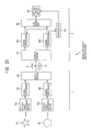
- FIG. 23 illustrates a second embodiment of the image-capturing/display system employing the present invention.
- components that correspond to the components in FIG. 3 , 4 , or 6 are indicated by the same reference numerals, and the description of those components will be omitted where appropriate.
- the image-capturing apparatus 1 includes two optical image-capturing devices 10 1 and 10 2 , two signal processors 12 1 and 12 2 , and a multiplexer 81 .
- the optical image-capturing devices 10 1 and 10 2 each have the same structure as the optical image-capturing device 10 of FIG. 4 .
- the optical image-capturing device 10 1 captures an image of an object S 1 and supplies the obtained image data to the signal processor 12 1 .
- the optical image-capturing device 10 2 captures an image of another object S 2 , different from the object S 1 , and supplies the obtained image data to the signal processor 12 2 .
- multiple cameras disposed around the object S 1 (N cameras are provided in the second embodiment, similar to what is shown in FIG. 4 ) capture images of the object S 1 .
- multiple cameras disposed around the object S 2 capture images of the object S 2 .
- the signal processors 12 1 and 12 2 each have the same structure as the signal processor 12 of FIG. 4 .
- the signal processors 12 1 and 12 2 respectively perform the same processing as the signal processor 12 of FIG. 4 on the image data of the objects S 1 and S 2 supplied from the optical image-capturing devices 10 1 and 10 2 .
- the data streams obtained are then supplied to the multiplexer 81 .
- the two data streams supplied from the signal processors 12 1 and 12 2 are multiplexed to form one data stream by the multiplexer 81 .
- the data stream is then supplied to the display apparatus 2 via the transmission medium 3 or the recording medium 4 .
- the display apparatus 2 includes an optical display device 20 , two signal processors 22 1 and 22 1 a controller 23 , a demultiplexer 91 , and a combining unit 92 .
- the data stream supplied from (the multiplexer 81 of) the image-capturing apparatus 1 is received by the demultiplexer 91 .
- the demultiplexer 91 demultiplexes the data stream supplied from the image-capturing apparatus 1 into the two data streams originally obtained in the signal processors 12 1 and 12 2 . Each of the two data streams is supplied to the corresponding one of the signal processors 22 1 and 22 2 .
- the signal processors 22 1 and 22 2 each have the same structure as the signal processor 22 of FIG. 6 .
- the signal processors 22 1 and 22 2 perform the same processing as the signal processor 22 of FIG. 6 on the data streams supplied from the demultiplexer 91 and obtained originally in the signal processors 12 1 and 12 2 .
- the image data of the objects S 1 and S 2 obtained are then supplied to the combining unit 92 .
- the image data of the object S 1 supplied from the signal processor 22 1 and the image data of the object S 2 supplied from the signal processor 22 2 are combined together (superimposed) by the combining unit 92 to generate combined image data.
- the image data of the objects S 1 and S 2 supplied from the respective signal processors 22 1 and 22 2 are images captured by the multiple cameras disposed around each of the objects S 1 and S 2 .
- the image data of the object S 1 captured from various directions are combined with the image data of the object S 2 captured from the same directions as those directions.
- the combining unit 92 it is also possible to combine together the image data of the object S 1 captured from various directions and the image data of the object S 2 captured from directions different from those directions. In this case, however, the capturing directions of the image data of the combined objects S 1 and S 2 must be separated by equal angles (equal phases).
- the combined image data obtained in the combining unit 92 is supplied to the optical display device 20 and is displayed in the optical display device 20 in the same manner as is displayed in the optical display device 20 of FIG. 6 . Accordingly, as is shown in FIG. 25 , the optical display device 20 of FIG. 23 displays a combined image of the object S 1 and the object S 2 .
- the optical display device 20 displays the combination of the two image data. This enables the user to check in detail the difference between the swings of the user and the professional golfer.
- the two image data obtained in the optical image-capturing devices 10 1 and 10 2 of the image-capturing apparatus 1 are multiplexed to form one data stream by the multiplexer 81 , and the data stream is supplied to the display apparatus 2 .
- multiple image-capturing apparatuses each having the same structure as the image-capturing apparatus 1 of FIG. 4 , in an area remote from the display apparatus 2 . Image data are thus sent to the display apparatus 2 of FIG. 23 from each image-capturing apparatus.
- the display apparatus 2 of FIG. 23 does not need the demultiplexer 91 . It is necessary, however, to provide for the display apparatus 2 an equal number of signal processors, which are equivalent to the signal processors 22 , as the number of the image-capturing apparatuses provided.
- the combining unit 92 may also combine the image data of the objects S 1 and S 2 according to their positional relationships and their scale variations. Furthermore, the combining unit 92 may, for example, combine the image data of the objects S 1 and S 2 while shifting the position of one of or both of the image data of the objects S 1 and S 2 .
- FIG. 26 illustrates another example of the optical display device 20 of FIG. 6 .
- components that correspond to the components in FIG. 6 are indicated by the same reference numerals, and the description of those components will be omitted where appropriate.
- the optical display device 20 of FIG. 26 has the same structure as the optical display device 20 of FIG. 6 .
- the drivers 24 1 to 24 7 are controlled by a controller 23 (see FIG. 6 ) and accordingly rotate the light-control screens 25 1 to 25 7 , for example, in phase and at the same angular rate.
- a controller 23 see FIG. 6
- the drivers 24 1 to 24 7 and the light-control screens 25 1 to 25 7 are disposed such that when the light-control screens 25 1 to 25 7 are viewed from one of the projectors 21 n positioned in the front direction of the screens, the ends of at least three screens overlap one another to define one screen having a size equivalent to at least three screens arranged side by side horizontally.
- the optical display device 20 of FIG. 26 even if each of the light-control screens 25 1 to 25 7 is small in size, the large screen defined by the light-control screens 25 1 to 25 7 can display a large image.
- the series of operations described above may be performed using hardware or software. If software is used for this series of operations, a software program is installed in, for example, a general-purpose computer.
- FIG. 27 illustrates an embodiment of a computer in which the program for running the series of operations is installed.
- the program may be preliminarily written onto a recording medium, such as a hard disc 105 and a ROM 103 , built inside the computer.
- the program may be temporarily or permanently stored in (written onto) a removable recording-medium 111 such as a floppy disc, a CD-ROM (Compact Disc Read Only Memory), an MO (Magneto Optical) disc, a DVD (Digital Versatile Disc), a magnetic disc, and a semiconductor memory.
- a removable recording-medium 111 such as a floppy disc, a CD-ROM (Compact Disc Read Only Memory), an MO (Magneto Optical) disc, a DVD (Digital Versatile Disc), a magnetic disc, and a semiconductor memory.
- the removable recording-medium 111 of this type may be distributed as packaged software.
- the program may be transferred to the computer from a download site by radio via satellite for Digital Satellite Broadcasting, or may be transferred to the computer by wire via a network such as a LAN (Local Area Network) and the Internet.
- the transferred program is thus received by a communicating unit 108 in the computer and is installed in an internal hard disc 105 .
- the computer includes a built-in CPU (Computer Processing Unit) 10 2 .
- the CPU 10 2 is connected to an input-output interface 110 via a bus 10 1 .
- an input unit 107 such as a keyboard, a mouse, and a microphone, so as to input a command to the CPU 102 via the input-output interface 110 , a program stored in the ROM (Read Only Memory) 103 is executed.
- ROM Read Only Memory
- a program stored in the hard disc 105 may be loaded onto a RAM (Random Access Memory) 104 so that the program is executed by the CPU 102 . Consequently, the CPU 102 performs the operation according to the flow charts described previously, or the operation according to the block diagrams described previously. According to need, for example, the CPU 102 outputs the result of the operation from an output unit 106 , such as an LCD (Liquid Crystal Display) and a speaker, via the input-output interface 110 . Alternatively, the result of the operation may be transmitted via the communicating unit 108 , or may be, for example, written onto the hard disc 105 .
- an output unit 106 such as an LCD (Liquid Crystal Display) and a speaker
- the steps describing the program for the computer to perform each operation do not necessarily need to be performed in the time order of the flow charts described above.
- the steps may be performed in parallel or individually (for example, by parallel processing or by object-oriented processing).
- the program may be either operated with one computer or operated with multiple computers in a distributed manner. Furthermore, the program may be transferred to a remote computer so as to be executed in that computer.
- FIG. 28A to FIG. 28D illustrate the differences among the image-capturing/display system of FIGS. 3 and 23 , the IP 3D-image system, and Zebra Imaging.
- the IP 3D-image system is capable of displaying images viewable from various viewing points of multiple users and does not have problems with displaying moving images. Furthermore, the IP 3D-image system is highly flexible in providing various viewing points for the users. However, as described previously, the IP 3D-image system has difficulties in providing images having high resolution.
- Zebra Imaging is capable of displaying images viewable from various viewing points of multiple users and can display images having high resolution. Furthermore, Zebra Imaging is highly flexible in providing various viewing points for the users, like the IP 3D-image system. However, as described previously, Zebra Imaging has difficulties in providing moving images.
- the image-capturing/display system of FIGS. 3 and 23 is not as high as the flexibility of the IP 3D-image system and Zebra Imaging, the image-capturing/display system is still capable of displaying images viewable from various viewing points of multiple users. Furthermore, the image-capturing/display system can display images having high resolution and does not have problems with displaying moving images.
- the applicant of the present invention has previously disclosed a method that uses optical paths of light rays of captured image data of an object, and information of the light rays, that is, pixel values corresponding to the light rays, so as to convert image data of an object into image data of the object viewable from a viewing point of a user (Japanese Patent Application No. 2002-161838).
- this method when the user relocates the viewing point to look at an image of an object displayed on a display, the image data displayed is equivalent to what the user visually perceives when the object is seen from the relocated viewing point in reality.
- a display of this type is called a “multi-view television” (a multiple-viewing-point image-displaying TV).
- this “multi-view television” can display high-resolution images and is also highly flexible in providing various viewing points for users.
- the “multi-view television” has only one display face, it is difficult to provide images viewable from various viewing points of multiple users.
- the light-control screen 25 is formed of a single screen in the above embodiments, the light-control screen 25 may be alternatively formed of, for example, three screens having the same structure as the light-control screen 25 of FIG. 12 .
- the three screens are connected together to form a triangular prism such that each of the display faces of the three screens faces outward.
- An axis extending through the center of the triangle in the bottom surface of the triangular prism may, for example, function as the rotational axis around or on which the prism may be rotated.
- high-resolution moving images can be viewed from various viewing points of multiple users.
Landscapes
- Physics & Mathematics (AREA)
- General Physics & Mathematics (AREA)
- Optics & Photonics (AREA)
- Engineering & Computer Science (AREA)
- Multimedia (AREA)
- Signal Processing (AREA)
- Testing, Inspecting, Measuring Of Stereoscopic Televisions And Televisions (AREA)
- Projection Apparatus (AREA)
- Overhead Projectors And Projection Screens (AREA)
- Closed-Circuit Television Systems (AREA)
Priority Applications (1)
| Application Number | Priority Date | Filing Date | Title |
|---|---|---|---|
| US11/906,916 US20090262185A1 (en) | 2002-06-05 | 2007-10-04 | Display apparatus and display method |
Applications Claiming Priority (3)
| Application Number | Priority Date | Filing Date | Title |
|---|---|---|---|
| JP2002-163682 | 2002-06-05 | ||
| JP2002163682A JP3787841B2 (ja) | 2002-06-05 | 2002-06-05 | 表示装置および表示方法 |
| PCT/JP2003/007100 WO2003104891A1 (ja) | 2002-06-05 | 2003-06-05 | 表示装置および表示方法 |
Related Child Applications (1)
| Application Number | Title | Priority Date | Filing Date |
|---|---|---|---|
| US11/906,916 Continuation US20090262185A1 (en) | 2002-06-05 | 2007-10-04 | Display apparatus and display method |
Publications (2)
| Publication Number | Publication Date |
|---|---|
| US20060152435A1 US20060152435A1 (en) | 2006-07-13 |
| US8310409B2 true US8310409B2 (en) | 2012-11-13 |
Family
ID=29727547
Family Applications (2)
| Application Number | Title | Priority Date | Filing Date |
|---|---|---|---|
| US10/485,635 Expired - Fee Related US8310409B2 (en) | 2002-06-05 | 2003-06-05 | Display device and display method |
| US11/906,916 Abandoned US20090262185A1 (en) | 2002-06-05 | 2007-10-04 | Display apparatus and display method |
Family Applications After (1)
| Application Number | Title | Priority Date | Filing Date |
|---|---|---|---|
| US11/906,916 Abandoned US20090262185A1 (en) | 2002-06-05 | 2007-10-04 | Display apparatus and display method |
Country Status (6)
| Country | Link |
|---|---|
| US (2) | US8310409B2 (ja) |
| EP (1) | EP1510857A4 (ja) |
| JP (1) | JP3787841B2 (ja) |
| KR (1) | KR100986045B1 (ja) |
| CN (1) | CN100437339C (ja) |
| WO (1) | WO2003104891A1 (ja) |
Cited By (1)
| Publication number | Priority date | Publication date | Assignee | Title |
|---|---|---|---|---|
| US20120146897A1 (en) * | 2009-08-28 | 2012-06-14 | National Institute Of Information And Communications Technology | Three-dimensional display |
Families Citing this family (24)
| Publication number | Priority date | Publication date | Assignee | Title |
|---|---|---|---|---|
| US7059733B2 (en) | 2003-03-18 | 2006-06-13 | Hitachi, Ltd. | Display apparatus |
| JP4843901B2 (ja) * | 2004-02-05 | 2011-12-21 | 株式会社日立製作所 | 表示装置 |
| JP4826700B2 (ja) * | 2004-02-18 | 2011-11-30 | 富士ゼロックス株式会社 | 立体表示装置 |
| WO2006027855A1 (ja) * | 2004-09-10 | 2006-03-16 | Hitachi, Ltd. | 表示装置及び撮像装置 |
| JP4645885B2 (ja) * | 2004-09-30 | 2011-03-09 | ソニー株式会社 | 表示装置および表示方法 |
| JP4704739B2 (ja) * | 2004-11-10 | 2011-06-22 | 直史 山内 | スクリーン及びこれを用いた画像投影システム |
| JP4616673B2 (ja) * | 2005-03-14 | 2011-01-19 | 株式会社日立製作所 | 表示装置及び撮像装置 |
| EP1967020B1 (en) | 2005-12-23 | 2010-11-24 | Koninklijke Philips Electronics N.V. | Rear projector and rear projecting method |
| US7630002B2 (en) * | 2007-01-05 | 2009-12-08 | Microsoft Corporation | Specular reflection reduction using multiple cameras |
| US7609906B2 (en) * | 2006-04-04 | 2009-10-27 | Mitsubishi Electric Research Laboratories, Inc. | Method and system for acquiring and displaying 3D light fields |
| CN101507276B (zh) * | 2006-08-18 | 2012-02-08 | 索尼株式会社 | 具有可换个性适配器的能自动重配置多媒体系统 |
| JP2009055094A (ja) * | 2007-08-23 | 2009-03-12 | Sharp Corp | 映像システム |
| KR101524680B1 (ko) | 2008-11-13 | 2015-06-01 | 삼성전자주식회사 | 방향성 라이트 필드 3d 디스플레이 장치 및 방법 |
| TWI406259B (zh) * | 2008-11-28 | 2013-08-21 | Innolux Corp | 三維顯示系統與三維顯示方法 |
| JP4598856B2 (ja) * | 2008-12-22 | 2010-12-15 | 嘉彦 北村 | 立体表示方法 |
| US20160007014A1 (en) * | 2013-03-15 | 2016-01-07 | Matthew HENDERSHOT | Equidistant stereo lens shader |
| CN103546672B (zh) * | 2013-11-07 | 2016-09-07 | 苏州君立软件有限公司 | 一种图像采集系统 |
| CN103616770B (zh) * | 2013-12-12 | 2016-02-17 | 北京理工大学 | 基于多投影机和透射式散射屏幕的周视三维显示装置 |
| CN108572460B (zh) | 2017-03-09 | 2021-04-20 | 华为技术有限公司 | 图像显示系统 |
| EP3924766A4 (en) * | 2019-02-16 | 2022-11-16 | LEIA Inc. | HORIZONTAL PARALLAX MULTIVIEW DISPLAY AND LIGHT CONTROL SCREEN PROCESS |
| CN112068327A (zh) * | 2020-09-29 | 2020-12-11 | 雷文昌 | 一种按中心轴旋转的全息投影仪及其像素排列方式 |
| CN114742591B (zh) * | 2022-04-21 | 2023-07-18 | 艺壹佳文化科技(广东)有限公司 | 一种用于展览的广告展示系统及展示方法 |
| US11977244B2 (en) * | 2022-04-29 | 2024-05-07 | Sony Interactive Entertainment Inc. | Method and system for generating a visual representation of a real-world object in three physical dimensions |
| WO2023212064A1 (en) * | 2022-04-29 | 2023-11-02 | Sony Interactive Entertainment Inc. | Apparatus and method for a volumetric display |
Citations (17)
| Publication number | Priority date | Publication date | Assignee | Title |
|---|---|---|---|---|
| US4853769A (en) * | 1987-06-16 | 1989-08-01 | Massachusetts Institute Of Technology | Time multiplexed auto-stereoscopic three-dimensional imaging system |
| US4868682A (en) | 1986-06-27 | 1989-09-19 | Yamaha Corporation | Method of recording and reproducing video and sound information using plural recording devices and plural reproducing devices |
| WO1992002845A1 (en) | 1990-08-08 | 1992-02-20 | Trutan Pty Limited | Multiple angle projection for 3-d imagery |
| JPH05341411A (ja) | 1992-06-09 | 1993-12-24 | Nec Corp | 3次元画像表示装置及び3次元画像表示方法 |
| JPH06273693A (ja) | 1993-03-23 | 1994-09-30 | Sony Corp | 画像表示装置および画像回転表示装置 |
| WO1997010523A1 (en) | 1995-09-15 | 1997-03-20 | Richmond Holographic Research & Development Limited | Projection system |
| US5678910A (en) * | 1990-08-08 | 1997-10-21 | Trutan Pty Limited | Multiple angle projection for 3-D imagery |
| US5854706A (en) * | 1996-10-15 | 1998-12-29 | Alb; Cristian I. | System for viewing stereoscopic images |
| WO2000017844A1 (en) | 1998-09-24 | 2000-03-30 | Actuality Systems, Inc. | Volumetric three-dimensional display architecture |
| WO2001005147A1 (en) | 1999-07-09 | 2001-01-18 | Sarnoff Corporation | Compact rear projection system using birefringent optics |
| US6183088B1 (en) * | 1998-05-27 | 2001-02-06 | Actuality Systems, Inc. | Three-dimensional display system |
| US20010017688A1 (en) * | 2000-02-29 | 2001-08-30 | Sanyo Electric Co., Ltd. | Projection type liquid crystal display |
| WO2001080204A2 (en) | 2000-04-14 | 2001-10-25 | C-360, Inc. | Illuminated viewing assembly, viewing system including the illuminated viewing assembly, and method of viewing therefor |
| JP2001356410A (ja) | 2000-06-14 | 2001-12-26 | Nippon Telegr & Teleph Corp <Ntt> | 投影型表示装置 |
| WO2002021851A2 (en) | 2000-09-07 | 2002-03-14 | Actuality Systems, Inc. | Volumetric display system |
| JP2002112094A (ja) | 2000-09-26 | 2002-04-12 | Nec Corp | パノラマプロジェクタ装置およびパノラマ撮影装置 |
| US20020145660A1 (en) * | 2001-02-12 | 2002-10-10 | Takeo Kanade | System and method for manipulating the point of interest in a sequence of images |
Family Cites Families (6)
| Publication number | Priority date | Publication date | Assignee | Title |
|---|---|---|---|---|
| US6084979A (en) * | 1996-06-20 | 2000-07-04 | Carnegie Mellon University | Method for creating virtual reality |
| JP3445536B2 (ja) * | 1999-10-04 | 2003-09-08 | 三洋電機株式会社 | 半導体装置 |
| US6669346B2 (en) * | 2000-05-15 | 2003-12-30 | Darrell J. Metcalf | Large-audience, positionable imaging and display system for exhibiting panoramic imagery, and multimedia content featuring a circularity of action |
| US7193645B1 (en) * | 2000-07-27 | 2007-03-20 | Pvi Virtual Media Services, Llc | Video system and method of operating a video system |
| US6822616B2 (en) * | 2002-12-03 | 2004-11-23 | Harris Corporation | Multi-layer capacitive coupling in phased array antennas |
| US20060139447A1 (en) * | 2004-12-23 | 2006-06-29 | Unkrich Mark A | Eye detection system and method for control of a three-dimensional display |
-
2002
- 2002-06-05 JP JP2002163682A patent/JP3787841B2/ja not_active Expired - Lifetime
-
2003
- 2003-06-05 CN CNB038011190A patent/CN100437339C/zh not_active Expired - Fee Related
- 2003-06-05 WO PCT/JP2003/007100 patent/WO2003104891A1/ja active Application Filing
- 2003-06-05 EP EP03733291A patent/EP1510857A4/en not_active Withdrawn
- 2003-06-05 US US10/485,635 patent/US8310409B2/en not_active Expired - Fee Related
- 2003-06-05 KR KR1020047001250A patent/KR100986045B1/ko not_active IP Right Cessation
-
2007
- 2007-10-04 US US11/906,916 patent/US20090262185A1/en not_active Abandoned
Patent Citations (22)
| Publication number | Priority date | Publication date | Assignee | Title |
|---|---|---|---|---|
| US4868682A (en) | 1986-06-27 | 1989-09-19 | Yamaha Corporation | Method of recording and reproducing video and sound information using plural recording devices and plural reproducing devices |
| US4853769A (en) * | 1987-06-16 | 1989-08-01 | Massachusetts Institute Of Technology | Time multiplexed auto-stereoscopic three-dimensional imaging system |
| US5678910A (en) * | 1990-08-08 | 1997-10-21 | Trutan Pty Limited | Multiple angle projection for 3-D imagery |
| WO1992002845A1 (en) | 1990-08-08 | 1992-02-20 | Trutan Pty Limited | Multiple angle projection for 3-d imagery |
| JPH05341411A (ja) | 1992-06-09 | 1993-12-24 | Nec Corp | 3次元画像表示装置及び3次元画像表示方法 |
| JPH06273693A (ja) | 1993-03-23 | 1994-09-30 | Sony Corp | 画像表示装置および画像回転表示装置 |
| US5537251A (en) | 1993-03-23 | 1996-07-16 | Sony Corporation | Rotating screen picture display apparatus |
| WO1997010523A1 (en) | 1995-09-15 | 1997-03-20 | Richmond Holographic Research & Development Limited | Projection system |
| US5854706A (en) * | 1996-10-15 | 1998-12-29 | Alb; Cristian I. | System for viewing stereoscopic images |
| US6183088B1 (en) * | 1998-05-27 | 2001-02-06 | Actuality Systems, Inc. | Three-dimensional display system |
| WO2000017844A1 (en) | 1998-09-24 | 2000-03-30 | Actuality Systems, Inc. | Volumetric three-dimensional display architecture |
| JP2002525686A (ja) | 1998-09-24 | 2002-08-13 | アクチュアリティー システムズ インコーポレイテッド | 容積的3次元表示装置 |
| US6487020B1 (en) | 1998-09-24 | 2002-11-26 | Actuality Systems, Inc | Volumetric three-dimensional display architecture |
| WO2001005147A1 (en) | 1999-07-09 | 2001-01-18 | Sarnoff Corporation | Compact rear projection system using birefringent optics |
| US6561649B1 (en) | 1999-07-09 | 2003-05-13 | Sarnoff Corporation | Compact rear projection system using birefringent optics |
| US20010017688A1 (en) * | 2000-02-29 | 2001-08-30 | Sanyo Electric Co., Ltd. | Projection type liquid crystal display |
| US20010048405A1 (en) | 2000-04-14 | 2001-12-06 | Salley Neil B. | Illuminated viewing assembly, viewing system including the illuminated viewing assembly, and method of viewing therefor |
| WO2001080204A2 (en) | 2000-04-14 | 2001-10-25 | C-360, Inc. | Illuminated viewing assembly, viewing system including the illuminated viewing assembly, and method of viewing therefor |
| JP2001356410A (ja) | 2000-06-14 | 2001-12-26 | Nippon Telegr & Teleph Corp <Ntt> | 投影型表示装置 |
| WO2002021851A2 (en) | 2000-09-07 | 2002-03-14 | Actuality Systems, Inc. | Volumetric display system |
| JP2002112094A (ja) | 2000-09-26 | 2002-04-12 | Nec Corp | パノラマプロジェクタ装置およびパノラマ撮影装置 |
| US20020145660A1 (en) * | 2001-02-12 | 2002-10-10 | Takeo Kanade | System and method for manipulating the point of interest in a sequence of images |
Cited By (2)
| Publication number | Priority date | Publication date | Assignee | Title |
|---|---|---|---|---|
| US20120146897A1 (en) * | 2009-08-28 | 2012-06-14 | National Institute Of Information And Communications Technology | Three-dimensional display |
| US8648773B2 (en) * | 2009-08-28 | 2014-02-11 | National Institute Of Information And Communications Technology | Three-dimensional display |
Also Published As
| Publication number | Publication date |
|---|---|
| CN100437339C (zh) | 2008-11-26 |
| US20060152435A1 (en) | 2006-07-13 |
| US20090262185A1 (en) | 2009-10-22 |
| WO2003104891A1 (ja) | 2003-12-18 |
| EP1510857A1 (en) | 2005-03-02 |
| KR20050004764A (ko) | 2005-01-12 |
| JP3787841B2 (ja) | 2006-06-21 |
| KR100986045B1 (ko) | 2010-10-08 |
| JP2004012644A (ja) | 2004-01-15 |
| CN1556938A (zh) | 2004-12-22 |
| EP1510857A4 (en) | 2008-06-04 |
Similar Documents
| Publication | Publication Date | Title |
|---|---|---|
| US8310409B2 (en) | Display device and display method | |
| US8248512B2 (en) | Image-capturing apparatus, image-capturing method, display apparatus, and display method | |
| US6665003B1 (en) | System and method for generating and displaying panoramic images and movies | |
| US7837330B2 (en) | Panoramic three-dimensional adapter for an optical instrument and a combination of such an adapter and such an optical instrument | |
| EP0764869B1 (en) | Autostereoscopic display apparatus | |
| US7168809B2 (en) | Stereoscopic display apparatus | |
| US5614941A (en) | Multi-image autostereoscopic imaging system | |
| CN108919503B (zh) | 一种基于视角导向层的集成成像360°桌面3d显示系统 | |
| US20060023065A1 (en) | Multiple program and 3D display with high resolution display and recording applications | |
| US7161740B2 (en) | Projector | |
| JP2002228974A (ja) | 立体画像表示装置 | |
| US8717425B2 (en) | System for stereoscopically viewing motion pictures | |
| US4349252A (en) | Stereoscopic motion picture-circular to linear scan translator (alternate screen)-method and apparatus | |
| JP2000308091A (ja) | 立体画像撮像装置 | |
| Watanabe et al. | Wide viewing angle projection-type integral 3D display system with multiple UHD projectors | |
| Collender | 3-D television, movies and computer graphics without glasses | |
| JP4324845B2 (ja) | 映像表示装置 | |
| JP3528392B2 (ja) | 擬似立体画像表示装置 | |
| JPH04355747A (ja) | 立体表示装置 | |
| Watanabe et al. | 3D Capture and Display Based on Spatial Imaging Technology | |
| KR930005476B1 (ko) | 입체영상기록, 재생장치 및 방법 | |
| Kim | Recent development of 3D display technology for new market | |
| KR20060006120A (ko) | 입체 영상 표시 장치 | |
| JP2000201360A (ja) | 3次元画像表示位置変換装置および方法 | |
| KR20060091543A (ko) | 무손실 편광형 입체 디스플레이 장치 |
Legal Events
| Date | Code | Title | Description |
|---|---|---|---|
| AS | Assignment |
Owner name: SONY CORPORATION, JAPAN Free format text: ASSIGNMENT OF ASSIGNORS INTEREST;ASSIGNORS:KONDO, TETSUJIRO;OKUMURA, YUJI;HAGA, TSUGIHIKO;AND OTHERS;REEL/FRAME:015786/0077;SIGNING DATES FROM 20040602 TO 20040607 Owner name: SONY CORPORATION, JAPAN Free format text: ASSIGNMENT OF ASSIGNORS INTEREST;ASSIGNORS:KONDO, TETSUJIRO;OKUMURA, YUJI;HAGA, TSUGIHIKO;AND OTHERS;SIGNING DATES FROM 20040602 TO 20040607;REEL/FRAME:015786/0077 |
|
| STCF | Information on status: patent grant |
Free format text: PATENTED CASE |
|
| FEPP | Fee payment procedure |
Free format text: PAYOR NUMBER ASSIGNED (ORIGINAL EVENT CODE: ASPN); ENTITY STATUS OF PATENT OWNER: LARGE ENTITY |
|
| FPAY | Fee payment |
Year of fee payment: 4 |
|
| FEPP | Fee payment procedure |
Free format text: MAINTENANCE FEE REMINDER MAILED (ORIGINAL EVENT CODE: REM.); ENTITY STATUS OF PATENT OWNER: LARGE ENTITY |
|
| LAPS | Lapse for failure to pay maintenance fees |
Free format text: PATENT EXPIRED FOR FAILURE TO PAY MAINTENANCE FEES (ORIGINAL EVENT CODE: EXP.); ENTITY STATUS OF PATENT OWNER: LARGE ENTITY |
|
| STCH | Information on status: patent discontinuation |
Free format text: PATENT EXPIRED DUE TO NONPAYMENT OF MAINTENANCE FEES UNDER 37 CFR 1.362 |
|
| FP | Lapsed due to failure to pay maintenance fee |
Effective date: 20201113 |