US8301402B2 - In-plane compressive strength evaluation device and method therefor - Google Patents
In-plane compressive strength evaluation device and method therefor Download PDFInfo
- Publication number
- US8301402B2 US8301402B2 US13/146,677 US200913146677A US8301402B2 US 8301402 B2 US8301402 B2 US 8301402B2 US 200913146677 A US200913146677 A US 200913146677A US 8301402 B2 US8301402 B2 US 8301402B2
- Authority
- US
- United States
- Prior art keywords
- compressive strength
- information
- plane compressive
- strength evaluation
- structural model
- Prior art date
- Legal status (The legal status is an assumption and is not a legal conclusion. Google has not performed a legal analysis and makes no representation as to the accuracy of the status listed.)
- Active
Links
Images




Classifications
-
- G—PHYSICS
- G01—MEASURING; TESTING
- G01N—INVESTIGATING OR ANALYSING MATERIALS BY DETERMINING THEIR CHEMICAL OR PHYSICAL PROPERTIES
- G01N3/00—Investigating strength properties of solid materials by application of mechanical stress
- G01N3/08—Investigating strength properties of solid materials by application of mechanical stress by applying steady tensile or compressive forces
-
- F—MECHANICAL ENGINEERING; LIGHTING; HEATING; WEAPONS; BLASTING
- F22—STEAM GENERATION
- F22B—METHODS OF STEAM GENERATION; STEAM BOILERS
- F22B1/00—Methods of steam generation characterised by form of heating method
- F22B1/02—Methods of steam generation characterised by form of heating method by exploitation of the heat content of hot heat carriers
- F22B1/16—Methods of steam generation characterised by form of heating method by exploitation of the heat content of hot heat carriers the heat carrier being hot liquid or hot vapour, e.g. waste liquid, waste vapour
-
- F—MECHANICAL ENGINEERING; LIGHTING; HEATING; WEAPONS; BLASTING
- F22—STEAM GENERATION
- F22B—METHODS OF STEAM GENERATION; STEAM BOILERS
- F22B37/00—Component parts or details of steam boilers
- F22B37/02—Component parts or details of steam boilers applicable to more than one kind or type of steam boiler
- F22B37/10—Water tubes; Accessories therefor
- F22B37/20—Supporting arrangements, e.g. for securing water-tube sets
-
- F—MECHANICAL ENGINEERING; LIGHTING; HEATING; WEAPONS; BLASTING
- F22—STEAM GENERATION
- F22B—METHODS OF STEAM GENERATION; STEAM BOILERS
- F22B37/00—Component parts or details of steam boilers
- F22B37/02—Component parts or details of steam boilers applicable to more than one kind or type of steam boiler
- F22B37/10—Water tubes; Accessories therefor
- F22B37/20—Supporting arrangements, e.g. for securing water-tube sets
- F22B37/205—Supporting and spacing arrangements for tubes of a tube bundle
- F22B37/206—Anti-vibration supports for the bends of U-tube steam generators
-
- G—PHYSICS
- G21—NUCLEAR PHYSICS; NUCLEAR ENGINEERING
- G21D—NUCLEAR POWER PLANT
- G21D1/00—Details of nuclear power plant
-
- G—PHYSICS
- G01—MEASURING; TESTING
- G01N—INVESTIGATING OR ANALYSING MATERIALS BY DETERMINING THEIR CHEMICAL OR PHYSICAL PROPERTIES
- G01N2203/00—Investigating strength properties of solid materials by application of mechanical stress
- G01N2203/02—Details not specific for a particular testing method
- G01N2203/0202—Control of the test
- G01N2203/0212—Theories, calculations
- G01N2203/0218—Calculations based on experimental data
-
- Y—GENERAL TAGGING OF NEW TECHNOLOGICAL DEVELOPMENTS; GENERAL TAGGING OF CROSS-SECTIONAL TECHNOLOGIES SPANNING OVER SEVERAL SECTIONS OF THE IPC; TECHNICAL SUBJECTS COVERED BY FORMER USPC CROSS-REFERENCE ART COLLECTIONS [XRACs] AND DIGESTS
- Y02—TECHNOLOGIES OR APPLICATIONS FOR MITIGATION OR ADAPTATION AGAINST CLIMATE CHANGE
- Y02E—REDUCTION OF GREENHOUSE GAS [GHG] EMISSIONS, RELATED TO ENERGY GENERATION, TRANSMISSION OR DISTRIBUTION
- Y02E30/00—Energy generation of nuclear origin
Definitions
- the present invention relates to an in-plane compressive strength evaluation device that analyzes in-plane compressive strength of a tube support plate that is used in a steam generator, and to a method therefor.
- primary cooling water that has been heated in a nuclear reactor is fed to a steam generator, secondary cooling water is heated in the steam generator with the heat of the primary cooling water to generate secondary steam, and the secondary steam is supplied to a steam turbine to rotate the steam turbine, thereby driving an electric generator.
- FIG. 9 is a diagram showing, in outline, the configuration of a steam generator that is used in a nuclear power plant.
- a steam generator 1 is provided with a solid outer cylinder 2 , a tube plate 3 that is formed integrally with the outer cylinder 2 , and a number of inverted U-shaped heat transfer tubes 7 both ends of which are inserted in and connected to the tube plate 3 .
- a number of heat transfer tubes 7 having several bend radii form a heat transfer tube bundle, and the heat transfer tube bundle is surrounded by an inner cylinder 4 and is supported horizontally by a number of tube support plates 5 .
- a number of through-holes for allowing the heat transfer tube 7 to pass through are formed in the tube support plates 5 .
- the tube support plates 5 are used for preventing vibration of the heat transfer tubes 7 and for maintaining the mutual spacing between the heat transfer tubes 7 .
- the mutual spacing between the heat transfer tubes 7 can be maintained, thus preventing vibration of the heat transfer tubes 7 , and, furthermore, even when a lateral load (a load exerted in the horizontal direction) is exerted due to an earthquake etc., this lateral load is borne by the tube support plate 5 .
- high-temperature heating fluid 6 flows into a first water chamber 8 , and this heating fluid 6 flows through the heat transfer tubes 7 , provides heat to be cooled, and then, flows out from a second water chamber 9 .
- the heating fluid 6 is, for example, a nuclear reactor coolant.
- feedwater 31 that has entered by flowing through a feedwater nozzle 30 flows down through the space between the inner cylinder 4 and the outer cylinder 2 , turns above the tube plate 3 , and flows upwards along the heat transfer tubes 7 . While flowing upwards, the feedwater 31 absorbs heat from the heating fluid 6 through heat exchange, is heated, is boiled, and becomes steam.
- This steam 33 flows out from a steam nozzle 34 and is directed to, for example, a steam turbine.
- FIG. 10 is a plan view of the tube support plate 5 taken from above the steam generator 1 .
- wedges 50 are provided on the outer periphery of the tube support plate 5 at prescribed intervals. When the tube support plate 5 is arranged in the steam generator, these wedges 50 fill the gap between the inner cylinder 4 and the tube support plate 5 .
- the through-holes 100 have, for example, a hexagonal shape, and protrusions 100 a , 100 b , and 100 c that protrude towards the center of the through hole 100 are respectively formed on, among the six sides 101 , 102 , 103 , 104 , 105 , and 106 that form the hexagonal shape, the alternate sides 102 , 104 , and 106 .
- the through-holes 100 have, for example, a hexagonal shape
- protrusions 100 a , 100 b , and 100 c that protrude towards the center of the through hole 100 are respectively formed on, among the six sides 101 , 102 , 103 , 104 , 105 , and 106 that form the hexagonal shape, the alternate sides 102 , 104 , and 106 .
- through-holes 100 are arranged on the tube support plate 5 so as to be aligned vertically and horizontally in a grid pattern.
- a gap is provided between the outer peripheral surface of the heat transfer tubes 7 and the inner peripheral surface of the through-holes 100 , and this gap provides a flow path for the secondary cooling water and the steam.
- the through-holes 100 have, in addition to a function of supporting the heat transfer tubes 7 , a flowpath function for allowing the secondary cooling water and the steam that flow upwards in the inner cylinder 4 to flow therethrough.
- the lateral load is also propagated to the tube support plate 5 .
- the in-plane compressive strength of the tube support plate 5 is not sufficient, there is a risk in that the through-holes 100 will be crushed to contact with the heat transfer tubes 7 , and the heat transfer tubes 7 will be deformed (damaged).
- the tube support plate 5 is required to have a certain in-plane compressive strength.
- an evaluation of the in-plane compressive strength of such a tube support plate 5 is performed by forming a small-scale test piece having the same structure as the tube support plate 5 , gradually applying a lateral load to this test piece, and reading out the value of the lateral load (hereinafter referred to as “stick load”) at which the through hole 100 that is formed in the tube support plate 5 is crushed and makes contact with the heat transfer tubes 7 .
- the reason for performing the evaluation using a test piece in this way is that, since the actual dimension of the tube support plate 5 is at least 3 m in diameter and can be as large as about 6 m in diameter, test facilities, test conditions, and so forth are restricted in several ways, and it is difficult to perform the in-plane compressive strength evaluation with the actual plate.
- the in-plane strength will differ, for example, between the case where the load is exerted in the direction of arrow A in the figure and the case where the load is exerted in the direction of arrow B in the figure.
- the tube support plate 5 has anisotropy in that the in-plane strength varies depending on the direction of the load exerted.
- the present invention has been conceived in light of the above-described situation, and an object thereof is to provide an in-plane compressive strength evaluation device that is capable of achieving reduction of cost and improvement of evaluation accuracy, as well as a method therefor.
- the present invention employs the following solutions.
- a first aspect of the present invention is an in-plane compressive strength evaluation device that is disposed in a steam generator and evaluates an in-plane compressive strength of a tube support plate, in which a number of through-holes, through which heat transfer tubes pass, are formed, the evaluation device including a memory unit in which, when a test piece having substantially a same structure as the tube support plate that is actually used is formed and an in-plane compressive strength evaluation is performed by exerting a load in a state where the heat transfer tubes having a prescribed length are inserted into the through-holes formed in the test piece, respectively, an evaluation result related to the load and a displacement of the test piece is stored as first information; a first analysis unit that obtains, by producing a structural model of the test piece and by performing a simulation of the in-plane compressive strength evaluation under same conditions as the in-plane compressive strength evaluation, second information that is an evaluation result related to the load and the displacement in the structural model; an adjustment unit that adjusts an elemental factor of the structural model that influences the
- the in-plane compressive strength evaluation is actually performed by forming a test piece having substantially the same structure as the tube support plate that is actually used, and by exerting a load in a state where the heat transfer tubes having the prescribed length are inserted into the through-holes that are formed in this test piece, respectively.
- an evaluation result related to the load and the displacement in the test piece obtained at this time is stored in the memory unit as the first information.
- the structural model of the test piece is produced by the first analysis unit, and the simulation of the in-plane compressive strength evaluation using this structural model of the test piece is performed under the same conditions as the actual conditions, thereby obtaining the second information, which is the evaluation result related to the load and the displacement in the structural model.
- the elemental factor of the structural model is adjusted by the adjustment unit such that the second information approaches the first information.
- the elemental factor that is adjusted at this time is the elemental factor that influences the in-plane compressive strength.
- the structural model is produced at the actual plate level by the second analysis unit by expanding the structural model of the test piece while taking over the elemental factor that is used when the second information approaches the first information most closely, and the in-plane compressive strength evaluation is performed by using this structural model.
- the elemental factor of the structural model of the test piece is adjusted such that the simulation result that is close to the evaluation result of the actual in-plane compressive strength evaluation that is performed using the test piece is obtained, and the simulation of the in-plane compressive strength evaluation is performed by expanding the structural model having the elemental factor that has provided the evaluation result closest to the actual evaluation result into the actual plate.
- test pieces are required to be prepared conventionally in order to consider anisotropy
- only one test piece is required since the test piece is only required for understanding the property of the in-plane compressive strength evaluation of the actual tube support plate. Therefore, it is possible to reduce the cost and effort required for forming the test piece.
- a load can be exerted under various conditions (angles, magnitudes, and so forth) in the simulation, and various evaluations can be performed.
- the elemental factors of the structural model that influence the above-mentioned in-plane compressive strength include, for example, material factors of the structural model and a deformable element factor that defines a deformation of the structural model.
- the material factors include, for example, a material hardening rule etc.
- the deformable element factor is a factor that is used to simply evaluate a three-dimensional model (x, y, and z) as a two-dimensional model (x and y), and it includes, for example, a plane stress factor, a plane strain factor, and so forth.
- the plane stress factor is a factor that defines that the stress in the z-axis direction is zero, in other words, that the structural model deforms freely in the z-axis direction.
- the plane strain factor is a factor that defines that the strain in the z-axis direction is zero, in other words, that the structural model does not deform in the z-axis direction.
- the plane stress factor is applied in a case where the thickness in the z-axis direction is small, and the plane strain factor is applied in a case where the thickness in the z-axis direction is sufficiently large.
- the second analysis unit may perform the in-plane compressive strength evaluation by exerting a sinusoidally or a cosinusoidally distributed load to wedges that are disposed on an outer periphery of the tube support plate at prescribed intervals.
- a second aspect of the present invention is an in-plane compressive strength evaluation method that evaluates an in-plane compressive strength of a tube support plate that is disposed in a steam generator and in which are formed a number of through-holes through which heat transfer tubes pass, the method including a process of forming a test piece having substantially a same structure as the tube support plate that is actually used, performing an in-plane compressive strength evaluation by exerting a load in a state where the heat transfer tubes having a prescribed length are inserted into the through-holes formed in the test piece, respectively, and obtaining an evaluation result related to the load and a displacement in the test piece as first information; a process of obtaining second information that is an evaluation result related to the load and the displacement in a structural model by producing the structural model of the test piece, and by performing a simulation of the in-plane compressive strength evaluation under same conditions as the in-plane compressive strength evaluation; a process of adjusting an elemental factor of the structural model that influences the in-plane compressive strength such that the
- the present invention affords an advantage in that cost reduction can be achieved and evaluation accuracy can be improved.
- FIG. 1 is a block diagram showing, in outline, the configuration of an in-plane compressive strength evaluation device according to one embodiment of the present invention.
- FIG. 2 is a functional block diagram showing, in an expanded manner, functions of an in-plane compressive strength evaluation device according to one embodiment of the present invention.
- FIG. 3 is a diagram showing, in outline, the configuration of a test piece.
- FIG. 4 is a diagram showing, in outline, the configuration of a loading jig that is used in an in-plane compressive strength evaluation.
- FIG. 5 is an example diagram showing evaluation results of an in-plane compressive strength evaluation.
- FIG. 6 is an example diagram showing a load exerted on a wedge in a simulation of an in-plane compressive strength evaluation of an actual plate.
- FIG. 7 is a flowchart showing operations of an in-plane compressive strength evaluation device according to one embodiment of the present invention.
- FIG. 8 is a diagram showing a comparison between evaluation results of an in-plane compressive strength evaluation of an actual test piece and evaluation results of an in-plane compressive strength evaluation by simulation.
- FIG. 9 is a diagram showing, in outline, the configuration of a steam generator used in a nuclear power plant.
- FIG. 10 is a plan view of a tube support plate taken from above the steam generator.
- FIG. 11 is an example diagram showing the shape and arrangement of through-holes.
- An in-plane compressive strength evaluation device is a device that evaluates the in-plane compressive strength of a tube support plate that is disposed in a steam generator, which is used in a nuclear power plant, and that has a number of through-holes through which heat transfer tubes pass through.
- the configuration of the steam generator and the configuration of the tube support plate, which is an evaluation object of the in-plane compressive strength evaluation device according to this embodiment, are shown in FIGS. 9 and 10 , and the explanations thereof are described as above.
- a number of through-holes 100 for allowing the heat transfer tubes 7 to pass through are formed in the central portion of the tube support plate 5 .
- the tube support plate is disposed horizontally in the steam generator 1 shown in FIG. 9 , and the heat transfer tubes 7 pass through the through-holes 100 perpendicularly.
- the through-holes 100 have, for example, a hexagonal shape.
- a gap is formed between the outer peripheral surface of the heat transfer tubes 7 and the inner peripheral surface of the through-holes 100 , and this gap serves as a flow path for the secondary cooling water and the steam.
- FIG. 1 shows, in outline, the configuration of an in-plane compressive strength evaluation device according to this embodiment.
- an in-plane compressive strength evaluation device 10 is a computer system (data processing system) that is provided with a CPU (central processing unit) 11 , a main storage device 12 such as RAM (random access memory), an auxiliary memory device 13 , an input device 14 such as a keyboard or a mouse, a display device 15 , and a communication device 16 that communicates with external devices to transfer information.
- a CPU central processing unit
- main storage device 12 such as RAM (random access memory)
- an input device 14 such as a keyboard or a mouse
- a display device 15 a display device 15
- a communication device 16 that communicates with external devices to transfer information.
- the auxiliary memory device 13 is a computer-readable recording medium, for example, a magnetic disk, a magneto-optical disk, a CD-ROM, a DVD-ROM, a semiconductor memory, and so forth.
- programs for example, an in-plane compressive strength evaluation program
- the CPU 11 reads out the program from the auxiliary memory device 13 to the main storage device 12 and executes the program to realize various processes.
- FIG. 2 is a functional block diagram showing, in an expanded manner, functions of the in-plane compressive strength evaluation device 10 .
- the in-plane compressive strength evaluation device 10 is provided with a memory unit 21 , a first analysis unit 22 , an adjustment unit 23 , and a second analysis unit 24 .
- a test piece having substantially the same structure as the tube support plate 5 which is actually used in the steam generator is formed, and the heat transfer tubes 7 having prescribed lengths are inserted into the through-holes 100 formed in the test piece, respectively.
- a load is exerted to perform the in-plane compressive strength evaluation.
- An evaluation result related to the load and the displacement in the test piece at this time is stored in the memory unit 21 as first information.
- the in-plane compressive strength evaluation is performed as described below, for example.
- FIG. 3 shows, in outline, a configuration of the test piece.
- the test piece 60 has a square shape and has a configuration in which a number of through-holes 100 are arranged between outer frame portions 40 .
- the outer frame portions 40 are provided only on two opposing sides (two sides along the X-direction in FIG. 3 ) of the four sides.
- FIG. 4 is a diagram showing, in outline, the configuration of a loading jig that is used in the in-plane compressive strength evaluation.
- the wedges 50 are disposed at the base of the loading jig, and the test piece 60 is fixed above these wedges 50 .
- the test piece 60 is fixed to the loading jig such that the outer frame portions 40 are positioned at the bottom and the top, in other words, such that, in FIG. 3 , the X-direction becomes the horizontal direction and Y-axis extends in the vertical direction.
- the heat transfer tubes 7 having the prescribed length are inserted into the respective through-holes 100 in the test piece 60 .
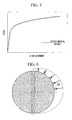
- FIG. 5 shows an example of the evaluation result of the in-plane compressive strength evaluation.
- the horizontal axis indicates the displacement and the vertical axis indicates the load.
- the change in the displacement is small due to elastic deformation; however, when the load exceeds a certain value, the displacement per prescribed amount of load becomes larger as the elastic deformation is replaced by plastic deformation.
- This stick load is the value of the load obtained when a load is exerted on the tube support plate 5 from the outer periphery thereof to cause a gradual deformation of the through-holes 100 that are formed in the plate, and the inner peripheral surface of any one of the through-holes 100 is caused to make contact with the outer peripheral surface of the heat transfer tubes 7 that pass through the through-holes 100 .
- This stick load is detected by, for example, an examiner checking the state of all the through-holes 100 every time the load is exerted in the prescribed unit, and by reading out the value of the load being exerted when at least one through hole in which the inner peripheral surface of the through-holes 100 is in contact with the outer peripheral surface of the heat transfer tubes 7 is found.
- first information In which the load and the displacement are associated, as shown in FIG. 5 , and the stick load are obtained by performing the in-plane compressive strength evaluation, this first information and stick load are stored in the memory unit of the in-plane compressive strength evaluation device (see FIG. 2 ).
- the configuration of the loading jig used in the in-plane compressive strength evaluation is not limited thereto, and a jig that is capable of performing a test in which a load is exerted on the test piece 60 and a relationship between the load and the displacement is obtained is adequate.
- the first analysis unit 22 by producing a structural model of the test piece 60 used in the above-described actual in-plane compressive strength evaluation and by performing a simulation of the in-plane compressive strength evaluation under the same conditions as the actual in-plane compressive strength evaluation, the first analysis unit 22 obtains second information in which the load and the displacement in the structural model are associated.
- the first analysis unit 22 has a program that produces the structural model of the test piece used in the above-described actual in-plane compressive strength evaluation on the basis of the information input from the input device 14 (see FIG. 1 ) and produces the structural model of the test piece by executing this program.
- the information input from the input device 14 includes, for example, a form factor, a material factor, a boundary condition, a deformable element factor, and so forth.
- the form factor includes, for example, the size of the entire model, the shape and arrangement of the through-holes, and so forth.
- the material factor includes, for example, the Young's modulus, a material hardening rule, and so forth.
- the boundary condition includes, for example, positions of the wedges 50 , constraining conditions of the edges of the test piece 60 , and so forth.
- the deformable element factor is the deformable element factor that defines the deformation of the structural model and is a factor that is used for simply evaluating a three-dimensional model (x, y, and z) as a two-dimensional model (x and y).
- the deformable element factor includes a plane stress factor, a plane strain factor, and so forth.
- the plane stress factor is a factor that defines the stress in the z-axis direction to be zero, in other words, that the structural model deforms freely in the z-axis direction.
- the plane strain factor is a factor that defines the strain in the z-axis direction to be zero, in other words, that the structural model does not deform in the z-axis direction.
- the plane stress factor is applied in a case where the thickness in the z-axis direction is small, and the plane strain factor is applied in a case where the thickness in the z-axis direction is sufficiently large.
- the above-mentioned information is input by an operator via the input device 14 , and the first analysis unit 22 produces the structural model on the basis of the information. Then, the first analysis unit 22 performs the simulation of the in-plane compressive strength evaluation under the same conditions as the actual in-plane compressive strength evaluation by using a numerical analysis method. By doing so, the second information in which the load and the displacement in the structural model are associated is obtained.
- An example of the numerical analysis method includes the finite element method.
- the adjustment unit 23 adjusts the elemental factors that influence the in-plane compressive strength in the structural model such that the second information obtained by the first analysis unit 22 approaches the first information stored in the memory unit 21 .
- the adjustment unit 23 first calculates a difference between the first information stored in the memory unit 21 and the second information obtained by the first analysis unit 22 and determines whether or not the maximum value of this difference falls within the pre-set allowable range.
- the material factor and the deformable element factor of the above-mentioned several elemental factors that are used to produce the structural model is changed to modify the structural model.
- the material hardening rule is adjusted as the material factor.
- the first analysis unit 22 then performs the in-plane compressive strength evaluation again using the modified structural model to obtain the second information that differs from the last time. Thereafter, the adjustment unit 23 compares this second information with the first information once again, and determines whether or not the maximum value of the difference falls within the allowable range. The adjustment unit 23 repeatedly updates the combination of the material hardening rule of the material factor and the deformable element factor until the maximum value of the difference falls within the allowable range and obtains the conditions of the factors with which the maximum value of the difference falls within the allowable range.
- the second analysis unit 24 expands the structural model, having the material factors that have been adjusted by the adjustment unit 23 such that the difference between the second information and the first information falls within the allowable range, into the structural form of the tube support plate 5 that is applied to the actual steam generator 1 and performs the in-plane compressive strength evaluation using the expanded structural model.
- the several information related to the actual plate are input through the input device 14 .
- the information that is input here includes, for example, the form factor and the boundary conditions.
- the second analysis unit 24 produces the structural model for the actual plate by updating the form factor and the boundary conditions, of the several input information that are used by the first analysis unit 22 for producing the structural model, with the input information that is input at this time.
- the material factor is inherited without any modification when the structural model of the test piece used in the first analysis unit 22 is expanded into the actual plate.
- the structural model of the actual plate can be produced in such a manner that a property that strongly influences the evaluation of the in-plane compressive strength is inherited without any modification. Therefore, the evaluation result of the in-plane compressive strength evaluation of the actual plate that is performed using this structural model is highly reliable.
- the simulation of the in-plane compressive strength evaluation with the structural model of the actual plate is performed by exerting a sinusoidal (or cosinusoidal) load on the respective wedges 50 .
- the in-plane compressive strength evaluation is performed.
- the stick load may also be detected in the simulation of the in-plane compressive strength evaluation of the actual plate.
- Step SA 1 an actual in-plane compressive strength evaluation using the test piece 60 is performed (Step SA 1 ), and the first information that associates the load and the displacement in the test piece, which are obtained at this time, is stored in the memory unit 21 (Step SA 2 ).
- the structural model of the test piece 60 is produced by the first analysis unit 22 , this structural model of the test piece 60 is used to perform the simulation of the in-plane compressive strength evaluation under the same conditions as the actual conditions, and the second information that associates the load and the displacement in the structural model is obtained (Step SA 3 ).
- the adjustment unit 23 adjusts the material factor of the structural model such that the second information approaches the first information and selects the deformable element factor (Step SA 4 ).
- the second analysis unit 24 then expands the structural model that has the material factor that provides the second information that is closest to the first information into the structural form of the tube support plate that is actually applied to the steam generator and performs the in-plane compressive strength evaluation using the expanded structural model (Step SA 5 ).
- the in-plane compressive strength evaluation result obtained with the structural model of the actual plate is stored in the memory unit 21 and is displayed on the display device 15 by being processed into a graph, thereby being presented to the operator (Step SA 6 ).
- the parameters of the structural model are calibrated such that the simulation result is close to the evaluation result of the actually performed in-plane compressive strength evaluation, and the simulation of the in-plane compressive strength evaluation is performed by expanding the structural model having the elemental factors that have provided the evaluation result closest to the actual evaluation result into the actual plate.
- test piece having the same property as the test piece can be produced, the direction in which the load is exerted can be set freely when performing the simulation. Therefore, although two test pieces are required to be prepared conventionally in order to consider the anisotropy, in this embodiment, only one test piece is required, and so, it is possible to reduce the cost and time needed for producing the test piece.
- the adjustment unit 23 may re-input values of the material factor and the deformable element factor through the input device 14 to achieve the adjustment of the material factor and the deformable element factor.
- the material factor is adjusted by displaying a graph, such as that shown in FIG. 8 , in which the first information and the second information are shown in comparison, on the display device 15 , and by an operator manually inputting a new value of the material factor through the input device 14 while checking this display screen.
- the adjustment of the elemental factor of the structural model is finished when the maximum value of the difference between the first information and the second information falls within the allowable range, and the structural model of the test piece having the elemental factor at this time is expanded into the actual plate, instead of this, for example, the adjustment of the elemental factor for the structural model may be finished when the maximum value of the difference between the first information and the second information becomes smallest.
- the properties as shown in FIG. 5 are employed as the first information and the second information, and the adjustment of the elemental factor for the structural model is finished when the maximum value of the difference between these properties falls within the allowable range; however, the stick loads may be employed as the first information and the second information.
- the adjustment unit 23 may finish the adjustment of the elemental factor for the structural model when, for example, the difference between the stick load obtained in the actual in-plane compressive strength evaluation and the stick load obtained in the first analysis unit 22 becomes the smallest, or when the difference between the stick loads falls within a preset allowable range (for example, within 5%).
Landscapes
- Engineering & Computer Science (AREA)
- Physics & Mathematics (AREA)
- General Engineering & Computer Science (AREA)
- Mechanical Engineering (AREA)
- Thermal Sciences (AREA)
- Life Sciences & Earth Sciences (AREA)
- General Health & Medical Sciences (AREA)
- Pathology (AREA)
- Analytical Chemistry (AREA)
- Biochemistry (AREA)
- Health & Medical Sciences (AREA)
- General Physics & Mathematics (AREA)
- Immunology (AREA)
- Chemical & Material Sciences (AREA)
- Sustainable Development (AREA)
- Sustainable Energy (AREA)
- High Energy & Nuclear Physics (AREA)
- Plasma & Fusion (AREA)
- Investigating Strength Of Materials By Application Of Mechanical Stress (AREA)
- Monitoring And Testing Of Nuclear Reactors (AREA)
Applications Claiming Priority (3)
| Application Number | Priority Date | Filing Date | Title |
|---|---|---|---|
| JP2009139463A JP5804668B2 (ja) | 2009-06-10 | 2009-06-10 | 面内圧縮強度評価装置及び方法 |
| JP2009-139463 | 2009-06-10 | ||
| PCT/JP2009/071149 WO2010143324A1 (ja) | 2009-06-10 | 2009-12-18 | 面内圧縮強度評価装置及び方法 |
Publications (2)
| Publication Number | Publication Date |
|---|---|
| US20110277554A1 US20110277554A1 (en) | 2011-11-17 |
| US8301402B2 true US8301402B2 (en) | 2012-10-30 |
Family
ID=43308588
Family Applications (1)
| Application Number | Title | Priority Date | Filing Date |
|---|---|---|---|
| US13/146,677 Active US8301402B2 (en) | 2009-06-10 | 2009-12-18 | In-plane compressive strength evaluation device and method therefor |
Country Status (5)
| Country | Link |
|---|---|
| US (1) | US8301402B2 (ja) |
| EP (1) | EP2442090B1 (ja) |
| JP (1) | JP5804668B2 (ja) |
| KR (1) | KR101284999B1 (ja) |
| WO (1) | WO2010143324A1 (ja) |
Families Citing this family (11)
| Publication number | Priority date | Publication date | Assignee | Title |
|---|---|---|---|---|
| CN104394884A (zh) * | 2012-03-21 | 2015-03-04 | 爱瑞泰克药物公司 | 用于治疗急性髓细胞白血病(aml)的药剂 |
| JP6317602B2 (ja) * | 2014-03-11 | 2018-04-25 | アサヒビール株式会社 | 座屈荷重の推定方法およびプログラム |
| JP6497588B2 (ja) * | 2015-08-31 | 2019-04-10 | 三菱重工業株式会社 | 熱交換器の変形応力特性取得方法、及び耐震評価方法 |
| JP6803244B2 (ja) * | 2017-01-20 | 2020-12-23 | 三菱重工業株式会社 | 熱交換器の解析方法 |
| CN109974956B (zh) * | 2017-12-28 | 2024-03-22 | 明门(中国)幼童用品有限公司 | 柱体支撑件强度测试装置 |
| KR101954824B1 (ko) * | 2018-07-31 | 2019-03-06 | 목포대학교산학협력단 | 비계용 연결브라켓 최종강도 시험장치 및 시험방법 |
| CN111967101B (zh) * | 2020-07-28 | 2025-01-24 | 同济大学 | 一种通过机械加压设计深海压力模拟装置的方法 |
| CN113158516B (zh) * | 2021-03-31 | 2023-02-28 | 中国飞机强度研究所 | 圆筒形结构强度试验件夹具有限元模型构建方法及其装置 |
| CN114582219B (zh) * | 2022-02-23 | 2023-08-11 | 山东高速工程建设集团有限公司 | 一种基坑邻接建筑物施工模拟装置 |
| CN114735237B (zh) * | 2022-06-14 | 2022-08-30 | 中国飞机强度研究所 | 一种飞机结构部件冲击试验面内面外静力施加结构及方法 |
| CN120741211B (zh) * | 2025-08-22 | 2025-11-14 | 北京理工大学 | 一种管道抗压性能检测装置 |
Citations (19)
| Publication number | Priority date | Publication date | Assignee | Title |
|---|---|---|---|---|
| JPH03255892A (ja) | 1990-03-07 | 1991-11-14 | Hitachi Ltd | 伝熱管支持構造 |
| JP2772275B2 (ja) | 1996-01-10 | 1998-07-02 | 三菱重工業株式会社 | 蒸気発生器内作業装置 |
| US5779442A (en) * | 1995-03-31 | 1998-07-14 | General Electric Company | Removable inner turbine shell with bucket tip clearance control |
| US5832421A (en) * | 1996-12-13 | 1998-11-03 | Siemens Corporate Research, Inc. | Method for blade temperature estimation in a steam turbine |
| US6775645B2 (en) * | 2001-11-14 | 2004-08-10 | Electric Power Research Institute, Inc. | Application of symbol sequence analysis and temporal irreversibility to monitoring and controlling boiler flames |
| US20040204900A1 (en) * | 2003-03-27 | 2004-10-14 | Namburi Adi Narayana | Method of on-line monitoring of radial clearances in steam turbines |
| JP2005190073A (ja) | 2003-12-25 | 2005-07-14 | Nissan Motor Co Ltd | 剛性解析方法およびそのプログラム |
| US7043409B1 (en) * | 1998-12-03 | 2006-05-09 | Siemens Aktiengesellschaft | Method and device for designing a technical system |
| JP2006258588A (ja) | 2005-03-16 | 2006-09-28 | Olympus Corp | 衝撃解析用材料物性の取得方法 |
| JP2006285381A (ja) | 2005-03-31 | 2006-10-19 | Yokohama Rubber Co Ltd:The | 構造体の設計方法 |
| US7231323B2 (en) * | 2001-12-21 | 2007-06-12 | International Paper Company | Environmental monitoring and reporting system for EPA cluster rule 010094 |
| US7260512B2 (en) * | 2002-10-21 | 2007-08-21 | Framatome Anp | Method for determining threshold value of a nuclear reactor operating parameter, corresponding system, computer programme and support |
| US7353140B2 (en) * | 2001-11-14 | 2008-04-01 | Electric Power Research Institute, Inc. | Methods for monitoring and controlling boiler flames |
| JP2008102041A (ja) | 2006-10-19 | 2008-05-01 | Toyota Central R&D Labs Inc | 構造物の剛性解析システムおよびそのプログラム |
| JP2008209063A (ja) | 2007-02-27 | 2008-09-11 | Mitsubishi Heavy Ind Ltd | 蒸気発生器の管支持板 |
| US20090043406A1 (en) * | 2005-01-28 | 2009-02-12 | Abb Research Ltd. | System and Method for Planning the Operation of, Monitoring Processes in, Simulating, and Optimizing a Combined Power Generation and Water Desalination Plant |
| US20110030866A1 (en) * | 2009-06-24 | 2011-02-10 | Fadel Georges M | Honeycomb structures for high shear flexure |
| US20110066258A1 (en) * | 2009-09-11 | 2011-03-17 | Siemens Corporation | System and Method for Energy Plant Optimization Using Mixed Integer-Linear Programming |
| US8065022B2 (en) * | 2005-09-06 | 2011-11-22 | General Electric Company | Methods and systems for neural network modeling of turbine components |
Family Cites Families (1)
| Publication number | Priority date | Publication date | Assignee | Title |
|---|---|---|---|---|
| JP3039332B2 (ja) * | 1995-08-09 | 2000-05-08 | 鹿島建設株式会社 | 制震構造物用可変減衰装置の試験方法 |
-
2009
- 2009-06-10 JP JP2009139463A patent/JP5804668B2/ja active Active
- 2009-12-18 EP EP09845846.6A patent/EP2442090B1/en active Active
- 2009-12-18 US US13/146,677 patent/US8301402B2/en active Active
- 2009-12-18 KR KR1020117017631A patent/KR101284999B1/ko active Active
- 2009-12-18 WO PCT/JP2009/071149 patent/WO2010143324A1/ja not_active Ceased
Patent Citations (25)
| Publication number | Priority date | Publication date | Assignee | Title |
|---|---|---|---|---|
| JPH03255892A (ja) | 1990-03-07 | 1991-11-14 | Hitachi Ltd | 伝熱管支持構造 |
| US5779442A (en) * | 1995-03-31 | 1998-07-14 | General Electric Company | Removable inner turbine shell with bucket tip clearance control |
| JP2772275B2 (ja) | 1996-01-10 | 1998-07-02 | 三菱重工業株式会社 | 蒸気発生器内作業装置 |
| US5832421A (en) * | 1996-12-13 | 1998-11-03 | Siemens Corporate Research, Inc. | Method for blade temperature estimation in a steam turbine |
| US7043409B1 (en) * | 1998-12-03 | 2006-05-09 | Siemens Aktiengesellschaft | Method and device for designing a technical system |
| US6775645B2 (en) * | 2001-11-14 | 2004-08-10 | Electric Power Research Institute, Inc. | Application of symbol sequence analysis and temporal irreversibility to monitoring and controlling boiler flames |
| US7353140B2 (en) * | 2001-11-14 | 2008-04-01 | Electric Power Research Institute, Inc. | Methods for monitoring and controlling boiler flames |
| US7231323B2 (en) * | 2001-12-21 | 2007-06-12 | International Paper Company | Environmental monitoring and reporting system for EPA cluster rule 010094 |
| US7493237B2 (en) * | 2001-12-21 | 2009-02-17 | International Paper Company | Environmental monitoring and reporting system |
| US7260512B2 (en) * | 2002-10-21 | 2007-08-21 | Framatome Anp | Method for determining threshold value of a nuclear reactor operating parameter, corresponding system, computer programme and support |
| US6853945B2 (en) * | 2003-03-27 | 2005-02-08 | General Electric Company | Method of on-line monitoring of radial clearances in steam turbines |
| US20040204900A1 (en) * | 2003-03-27 | 2004-10-14 | Namburi Adi Narayana | Method of on-line monitoring of radial clearances in steam turbines |
| JP2005190073A (ja) | 2003-12-25 | 2005-07-14 | Nissan Motor Co Ltd | 剛性解析方法およびそのプログラム |
| US20090043406A1 (en) * | 2005-01-28 | 2009-02-12 | Abb Research Ltd. | System and Method for Planning the Operation of, Monitoring Processes in, Simulating, and Optimizing a Combined Power Generation and Water Desalination Plant |
| JP2006258588A (ja) | 2005-03-16 | 2006-09-28 | Olympus Corp | 衝撃解析用材料物性の取得方法 |
| JP2006285381A (ja) | 2005-03-31 | 2006-10-19 | Yokohama Rubber Co Ltd:The | 構造体の設計方法 |
| US8065022B2 (en) * | 2005-09-06 | 2011-11-22 | General Electric Company | Methods and systems for neural network modeling of turbine components |
| JP2008102041A (ja) | 2006-10-19 | 2008-05-01 | Toyota Central R&D Labs Inc | 構造物の剛性解析システムおよびそのプログラム |
| CA2677871A1 (en) | 2007-02-27 | 2008-10-09 | Mitsubishi Heavy Industries, Ltd. | Tube support plate of steam generator |
| WO2008120487A1 (ja) | 2007-02-27 | 2008-10-09 | Mitsubishi Heavy Industries, Ltd. | 蒸気発生器の管支持板 |
| EP2123977A1 (en) | 2007-02-27 | 2009-11-25 | Mitsubishi Heavy Industries, Ltd. | Tube support plate of steam generator |
| US20100018687A1 (en) | 2007-02-27 | 2010-01-28 | Mitsubishi Heavy Industries, Ltd. | Tube support plate of steam generator |
| JP2008209063A (ja) | 2007-02-27 | 2008-09-11 | Mitsubishi Heavy Ind Ltd | 蒸気発生器の管支持板 |
| US20110030866A1 (en) * | 2009-06-24 | 2011-02-10 | Fadel Georges M | Honeycomb structures for high shear flexure |
| US20110066258A1 (en) * | 2009-09-11 | 2011-03-17 | Siemens Corporation | System and Method for Energy Plant Optimization Using Mixed Integer-Linear Programming |
Non-Patent Citations (1)
| Title |
|---|
| International Search Report for PCT/JP2009/071149, mailing date of Feb. 16, 2010. |
Also Published As
| Publication number | Publication date |
|---|---|
| EP2442090A1 (en) | 2012-04-18 |
| KR101284999B1 (ko) | 2013-07-10 |
| JP5804668B2 (ja) | 2015-11-04 |
| EP2442090A4 (en) | 2015-04-01 |
| US20110277554A1 (en) | 2011-11-17 |
| JP2010286317A (ja) | 2010-12-24 |
| EP2442090B1 (en) | 2016-04-20 |
| WO2010143324A1 (ja) | 2010-12-16 |
| KR20110102479A (ko) | 2011-09-16 |
Similar Documents
| Publication | Publication Date | Title |
|---|---|---|
| EP2442090B1 (en) | Inplane compressive strength evaluation device and method | |
| JP6086752B2 (ja) | 蒸気発生器の耐震評価方法 | |
| Lee et al. | Creep-fatigue damage evaluation of sodium to air heat exchanger in sodium test loop facility | |
| Kim | Structural analysis of CSB and LSS for APR1400 RVI CVAP | |
| JP6803244B2 (ja) | 熱交換器の解析方法 | |
| EP3467688B1 (en) | Contact force evaluation method | |
| CN121580549B (zh) | 多工况下弹塑性分析与强度校验方法、装置、设备及介质 | |
| Janulionis et al. | Numerical simulation of low-cycle fatigue test of welded 9Cr-1Mo steel at 550° C | |
| CN107369482A (zh) | 单根快堆组件热弯曲试验约束装置及热变形接触测量方法 | |
| JP2014063262A (ja) | 応力分布推定方法、これを用いる解析方法及び解析システム | |
| JP6497588B2 (ja) | 熱交換器の変形応力特性取得方法、及び耐震評価方法 | |
| WO2025145660A1 (zh) | 一种蒸汽发生器传热管束运维辅助方法、系统、介质及设备 | |
| Kim et al. | Hydraulic and Structural Analysis Methodology of RVI CVAP in Shin-Kori 4 | |
| CN107389434B (zh) | 60°扇区快堆组件约束装置及热变形接触测量方法 | |
| Lan et al. | A study on the seismic test of a planar model of the gas-cooled microreactor | |
| Schettino et al. | Efficacy of beam-type finite elements in the evaluation of lateral stiffness of 16× 16 fuel assemblies by strengthening mechanisms | |
| Hirota et al. | Seismic Test and Seismic Response Analysis of U-Shaped Tube Bundle With Triangular Arrays in Steam Generator | |
| Broc et al. | Core mechanical dynamics experiment in the Phenix reactor | |
| Fontaine et al. | Recent analyses of PHENIX End of Life Tests and perspectives | |
| Shaw et al. | Assessment of compact heat exchanger design following elastic perfectly plastic methodology | |
| Parsi et al. | Dynamic response characteristics of fuel-block assemblies in a horizontal, compact HTGR | |
| CN107389439B (zh) | 单排快堆组件热弯曲试验约束装置及热变形接触测量方法 | |
| Schettino et al. | Numerical analysis of the spacer grids' compression strength | |
| Shaw et al. | Critical Evaluation of a Novel Analysis Technique for Assessment of Printed Circuit Heat Exchangers in High-Temperature Nuclear Service | |
| Bonelli et al. | Thermal-hydraulic and structural analysis of a helium-cooled first wall mock-up |
Legal Events
| Date | Code | Title | Description |
|---|---|---|---|
| AS | Assignment |
Owner name: MITSUBISHI HEAVY INDUSTRIES, LTD., JAPAN Free format text: ASSIGNMENT OF ASSIGNORS INTEREST;ASSIGNORS:OGAWA, NAOKI;SHIMAMURA, KENGO;REEL/FRAME:026685/0453 Effective date: 20110621 |
|
| STCF | Information on status: patent grant |
Free format text: PATENTED CASE |
|
| FEPP | Fee payment procedure |
Free format text: PAYOR NUMBER ASSIGNED (ORIGINAL EVENT CODE: ASPN); ENTITY STATUS OF PATENT OWNER: LARGE ENTITY |
|
| FPAY | Fee payment |
Year of fee payment: 4 |
|
| MAFP | Maintenance fee payment |
Free format text: PAYMENT OF MAINTENANCE FEE, 8TH YEAR, LARGE ENTITY (ORIGINAL EVENT CODE: M1552); ENTITY STATUS OF PATENT OWNER: LARGE ENTITY Year of fee payment: 8 |
|
| MAFP | Maintenance fee payment |
Free format text: PAYMENT OF MAINTENANCE FEE, 12TH YEAR, LARGE ENTITY (ORIGINAL EVENT CODE: M1553); ENTITY STATUS OF PATENT OWNER: LARGE ENTITY Year of fee payment: 12 |