US8243935B2 - Sound image localization control apparatus - Google Patents
Sound image localization control apparatus Download PDFInfo
- Publication number
- US8243935B2 US8243935B2 US11/916,799 US91679906A US8243935B2 US 8243935 B2 US8243935 B2 US 8243935B2 US 91679906 A US91679906 A US 91679906A US 8243935 B2 US8243935 B2 US 8243935B2
- Authority
- US
- United States
- Prior art keywords
- sound
- image localization
- controlling means
- sound image
- control apparatus
- Prior art date
- Legal status (The legal status is an assumption and is not a legal conclusion. Google has not performed a legal analysis and makes no representation as to the accuracy of the status listed.)
- Expired - Fee Related, expires
Links
Images


Classifications
-
- H—ELECTRICITY
- H04—ELECTRIC COMMUNICATION TECHNIQUE
- H04S—STEREOPHONIC SYSTEMS
- H04S1/00—Two-channel systems
- H04S1/002—Non-adaptive circuits, e.g. manually adjustable or static, for enhancing the sound image or the spatial distribution
-
- H—ELECTRICITY
- H04—ELECTRIC COMMUNICATION TECHNIQUE
- H04S—STEREOPHONIC SYSTEMS
- H04S7/00—Indicating arrangements; Control arrangements, e.g. balance control
- H04S7/30—Control circuits for electronic adaptation of the sound field
-
- H—ELECTRICITY
- H04—ELECTRIC COMMUNICATION TECHNIQUE
- H04R—LOUDSPEAKERS, MICROPHONES, GRAMOPHONE PICK-UPS OR LIKE ACOUSTIC ELECTROMECHANICAL TRANSDUCERS; DEAF-AID SETS; PUBLIC ADDRESS SYSTEMS
- H04R2499/00—Aspects covered by H04R or H04S not otherwise provided for in their subgroups
- H04R2499/10—General applications
- H04R2499/13—Acoustic transducers and sound field adaptation in vehicles
-
- H—ELECTRICITY
- H04—ELECTRIC COMMUNICATION TECHNIQUE
- H04S—STEREOPHONIC SYSTEMS
- H04S2400/00—Details of stereophonic systems covered by H04S but not provided for in its groups
- H04S2400/13—Aspects of volume control, not necessarily automatic, in stereophonic sound systems
Definitions
- the present invention relates to a sound image localization control apparatus.
- FIG. 9 shows a sound reproducing apparatus 1 , which is disclosed in patent document 1, provided in a front seat of a vehicle.
- a sound reproducing apparatus 1 which is disclosed in patent document 1, provided in a front seat of a vehicle.
- two passengers L 1 and L 2 in the vehicle as listeners hear signal B 1 , which is reproduced by a recording device, by their respective left ears and hear signal B 2 , which is reproduced by the recording device, by their respective right ears
- a similar acoustical effect of contents stored in a recording device 2 is exerted on each of the passengers.
- four speakers 3 a , 3 b , 3 c , and 3 d are provided and are connected to amplifiers 4 a , 4 b , 4 c , and 4 d , respectively.
- Each speaker is paired with a corresponding amplifier so as to form acoustic generation means.
- acoustic information recorded by using a well-known binaural recording system is stored in the recording device 2 .
- the recording device 2 is connected to each of the amplifiers 4 a , 4 b , 4 c , and 4 d via an inverse filter network 5 structured in a procedure described below.
- h 11 to h 41 are shown.
- a method for calculating the acoustic transfer function hij is described.
- a test signal generator 6 connected to each of the amplifiers 4 a , 4 b , 4 c , and 4 d generates a wideband signal such as a white noise and calculates the acoustic transfer function hij by using sounds S 1 , S 2 , S 3 , and S 4 generated from the speakers 3 a , 3 b , 3 c , and 3 d , respectively; and sounds M 1 , M 2 , M 3 , and M 4 measured by both ears of dummy heads D 1 and D 2 which are placed in assumed positions of passengers.
- the amplifiers are each activated sequentially.
- the inverse filter network 5 as shown in FIG. 9 is designed so as to satisfy equation 4 and is provided before the amplifiers 4 a , 4 b , 4 c , and 4 d , and a signal for a left ear and a signal for a right ear are inputted to the inverse filter network, as a substitute for an output from the test signal generator 6 , the signal for the left ear and the signal for the right ear become a signal for a left ear and a signal for a right ear of each dummy head D 1 and D 2 .
- the signal for the left ear and the signal for the right ear are inputted to a left-hand input section and a right-hand input section, respectively, of the inverse filter network 5 shown in FIG. 9 .
- Elements which configure the inverse filter network 5 are each represented by the following equations.
- FIG. 11 is a diagram showing an acoustic transfer function G 1 between a virtual sound source 7 and the dummy head D 1 , and an acoustic transfer function G 2 between a virtual sound source 7 and the dummy head D 1 .
- FIG. 12 is a diagram showing a sound reproducing apparatus for positioning a sound image in a predetermined direction. Identical components to those in FIG. 9 bear the identical reference characters.
- the predetermined acoustic transfer functions Gland G 2 are set as coefficients in filters 8 a and 8 b , respectively.
- a monophonic sound source 9 in which not a binaural-recorded sound but a monophonic signal B 0 is recorded, is used as a sound source.
- a sound at a left ear position of each of passengers L 1 and L 2 is G 1 •B 0 and a sound at a right ear position of each of passengers L 1 and L 2 is G 2 •B 0 . Therefore, each sound is listened as if the sound is coming from the direction of the virtual sound source shown in FIG. 7 .
- the monophonic signal B 0 may be processed in advance by using the acoustic transfer functions G 1 and G 2 , or the acoustic transfer functions G 1 and G 2 may be incorporated into the elements configuring the inverse filter network, in order to produce the same effect.
- Patent Document 1 Japanese Laid-Open Patent Publication No. 6-165298
- an object of the present invention is to provide a sound image localization control apparatus which allows a plurality of users to variably adjust the acoustical effect individually without diminishing a sound image localization effect of a sound reproducing apparatus which performs sound image localization for the plurality of users.
- the object of the present invention is achieved by a sound image localization control apparatus having a configuration described below.
- the sound image localization control apparatus comprises: processing characteristic setting means for setting a processing characteristic such that acoustic transfer functions for at least two predetermined positions each represent a desired characteristic; controlling means for receiving an acoustic signal and the processing characteristic which is set by the processing characteristic setting means, and performing signal processing; and sound reproducing means for receiving an output from the controlling means.
- the object of the present invention is achieved by a sound image localization control method described below.
- the sound image localization control method is for a sound image localization control system capable of producing a common sound image localization effect at a plurality of predetermined positions by processing in a plurality of digital filters an acoustic signal outputted from a sound source so as to output the acoustic signal from a plurality of speakers, comprising: a first multiplication step of multiplying a value based on a sound volume control signal and/or a sound quality control signal for a first predetermined position by a first reference coefficient for the first predetermined position, the first reference coefficient being stored in a storage area; a second multiplication step of multiplying a value based on a sound volume control signal and/or a sound quality control signal for a second predetermined position by a second reference coefficient for the second predetermined position, the second reference coefficient being stored in the storage area; an addition step of adding a multiplication result of the first multiplication step to a multiplication result of the second multi
- the object of the present invention is achieved by a sound image localization control program described below.
- the sound image localization control program is for a sound image localization control system capable of producing a common sound image localization effect at a plurality of predetermined positions by processing in a plurality of digital filters an acoustic signal outputted from a sound source so as to output the acoustic signal from a plurality of speakers, the sound image localization control program causing a computer to execute: a first multiplication step of multiplying a value based on a sound volume control signal and/or a sound quality control signal for a first predetermined position by a first reference coefficient for the first predetermined position, the first reference coefficient being stored in a storage area; a second multiplication step of multiplying a value based on a sound volume control signal and/or a sound quality control signal for a second predetermined position by a second reference coefficient for the second predetermined position, the second reference coefficient being stored in the storage area; an addition step of adding a multiplication result of the first multi
- the object of the present invention is achieved by an integrated circuit having a configuration described below.
- the integrated circuit is used for a sound image localization control apparatus and is capable of reading from a memory storing at least two processing characteristic coefficients corresponding to at least two predetermined positions, respectively, the at least two processing characteristic coefficients, the integrated circuit comprising: a processing characteristic setting section for setting a processing characteristic by using the at least two processing characteristic coefficients stored in the memory such that acoustic transfer functions for the at least two predetermined positions each represent a desired characteristic; and a controlling section for receiving an acoustic signal and the processing characteristic which is set by the processing characteristic setting section and performing signal processing to generate an output signal to a sound reproducing section.
- a sound image localization control apparatus which allows a plurality of users to variably adjust the acoustical effect individually without diminishing the sound image localization effect of a sound reproducing apparatus which performs sound image localization for the plurality of users.
- FIG. 1 is a schematic view showing a configuration of a sound image localization control apparatus according to a first embodiment.
- FIG. 2 is a schematic view showing a configuration of the sound image localization control apparatus which realizes both simultaneous sound image localization control and individual sound volume adjustment for four users.
- FIG. 3 is a schematic view of a configuration of the sound image localization control apparatus which realizes both the simultaneous sound image localization control and the individual sound volume adjustment in the case where a sound source is a stereo sound source.
- FIG. 4 is a schematic view showing a configuration of the sound image localization control apparatus according to a second embodiment.
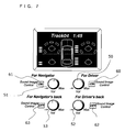
- FIG. 5 is a diagram showing an example where the sound image localization control apparatus is applied to a vehicle.
- FIG. 6 is a diagram showing an example where the sound image localization control apparatus is applied to a vehicle.
- FIG. 7 is a diagram showing an example where the sound image localization control apparatus is applied to a vehicle.
- FIG. 8 is a diagram showing an example where the sound image localization control apparatus is applied to a home theatre.
- FIG. 9 is a schematic view showing a configuration of a conventional sound reproducing apparatus.
- FIG. 10 is a diagram showing a method for calculating a transfer function.
- FIG. 11 is a diagram showing target transfer functions.
- FIG. 12 is a schematic view showing a configuration of a conventional sound reproducing apparatus which performs sound image localization control.
- FIG. 13 is a diagram showing an example where the sound image localization control apparatus is provided for a television receiver.
- FIG. 1 is a schematic view showing a configuration of a sound image localization control apparatus according to a first embodiment.
- the sound image localization control apparatus according to the present embodiment allows two users to simultaneously share a common sound image localization effect and to individually adjust sound volumes.
- the sound image localization control apparatus mainly comprises a sound source 10 , speakers 3 a , 3 b , 3 c , and 3 d , a control processing section 12 , synthesis parameter setting means 13 , and filter coefficient calculating means 14 .
- the synthesis parameter setting means 13 and the filter coefficient calculating means 14 correspond to processing characteristic setting means.
- the control processing section 12 corresponds to controlling means, and the speakers 3 a , 3 b , 3 c , and 3 d correspond to sound reproducing means.
- the sound source 10 may be a monophonic sound source, one channel signal source among multi-channel sound sources, or a sound source synthesized from a plurality of sound sources among the multi-channel sound sources.
- a monophonic sound source is used as the sound source 10 will be described for ease of description.
- the control processing section 12 includes control digital filters 11 a , 11 b , 11 c , and 11 d .
- An output signal from the sound source 10 is inputted to each of the control digital filters 11 a , 11 b , 11 c , and 11 d .
- the synthesis parameter setting means 13 is an interface for each user to adjust the sound volume.
- the filter coefficient calculating means 14 calculates a filter coefficient for each of the control digital filters 11 a , 11 b , 11 c , and 11 d in accordance with an output signal from the synthesis parameter setting means 13 so as to input the filter coefficient to the control processing section 12 .
- passengers L 1 and L 2 , acoustic transfer functions h 11 , h 21 , h 31 , and h 41 , and measured sounds M 1 , M 2 , M 3 , and M 4 are identical to those shown in FIG. 9 and thus detailed descriptions thereof will be omitted.
- a method for designing the control digital filters 11 a , 11 b , 11 c , and 11 d for producing the sound image localization effect will be described.
- 11 is a targeted position for sound image localization control and transfer functions of the control digital filters 11 a , 11 b , 11 c , and 11 d are C 1 , C 2 , C 3 , and C 4 , respectively, user L 1 hears, by both ears, M 1 and M 2 satisfying the following equation and user L 2 hears, by both ears, M 3 and M 4 satisfying the following equation.
- Equation 23 is transformed as follows.
- the filter coefficient calculating means 14 separately stores a filter coefficient satisfying a transfer function for former two members of the transfer function for each of the filters, represented by equation 27, and a filter coefficient satisfying a transfer function for latter two members of the transfer function for each of the filters, represented by equation 27.
- the filter coefficient calculating means 14 stores as reference coefficients eight filter coefficients (C 11 , C 12 , C 21 , C 22 , C 31 , C 32 , C 41 , C 42 ) satisfying transfer functions represented by equation 28, which includes the target transfer functions G 1 and G 2 .
- the reference coefficients each correspond to a processing characteristic coefficient.
- synthesis parameter setting means 13 information about a sound volume at which each user desires to listen is inputted to the synthesis parameter setting means 13 .
- the synthesis parameter setting means 13 inputs information about the ⁇ times sound volume and the ⁇ times sound volume to the filter coefficient calculating means 14 .
- the filter coefficient calculating means 14 calculates filter coefficients, by using the following equation, in accordance with information about the sound volumes, which is inputted from the synthesis parameter setting means 13 .
- the filter coefficient calculating means 14 sets the filter coefficients satisfying transfer functions obtained by equation 29, in the control processing section 12 . These filter coefficients are used as coefficients for the control digital filters 11 a , 11 b , 11 c , and 11 d.
- the former two members of equation 27 are associated with M 1 and M 2 .
- the former two members determine the acoustical effect on user L 1 .
- the latter two members are associated with M 3 and M 4 and therefore determine the acoustical effect on user L 2 .
- the sound volume at which user L 1 listens is increased by ⁇ times.
- the sound volume at which user L 2 listens is increased by ⁇ times.
- the filter coefficients are stored separately for each user (to be more precise, for each position at which a reproduced sound is heard) in consideration of effects of the acoustic transfer functions on the users.
- a coefficient (processing characteristic) determined by adding values each obtained by multiplying the reference coefficient (processing characteristic coefficient) by a constant number as represented by equation 29, it becomes possible to individually set the sound volume for each user while the sound image localization control effect is being maintained with a small amount of arithmetic processing.
- the sound image localization control apparatus is typically realized by using software.
- a program for causing a computer to execute the above-described processing of the sound image localization control is stored in a computer-readable recording medium, e.g., a hard disk, a CD-ROM, an MO, a DVD, a semiconductor memory, or the like.
- the present invention is not limited thereto.
- the configuration may allow each user to adjust a frequency characteristic individually.
- each user inputs information about a desired frequency characteristic such as a low boost to the synthesis parameter setting means 13 .
- the filter coefficient calculating means 14 determines filter coefficients by using the following equation.
- FIG. 2 is a schematic view showing a configuration of the sound image localization control apparatus which realizes both simultaneous sound image localization control and individual sound volume adjustment for four users L 1 , L 2 , L 3 and L 4 .
- the sound image localization control apparatus shown in FIG. 2 has almost the same configuration as that shown in FIG. 1 . However, there are differences as follows.
- control processing section 12 includes control digital filters 11 a , 11 b , 11 c , 11 d , 11 e , 11 f , 11 g , and 11 h .
- M 1 and M 2 each represent a sound at the position of an ear of user L 1
- M 3 and M 4 each represent a sound at the position of an ear of user L 2
- M 5 and M 6 each represent a sound at the position of an ear of user L 3
- M 7 and M 8 each represent a sound at the position of an ear of user L 4 .
- control digital filters 11 a , 11 b , 11 c , 11 d , 11 e , 11 f , 11 g , and 11 h for performing simultaneous sound image localization control for four users, and operations of the synthesis parameter setting means 13 , the filter coefficient calculating means 14 and the control processing section 12 , which are for performing individual sound volume adjustment for four users.
- [ M 1 M 2 M 3 M 4 M 5 M 6 M 7 M 8 ] [ h 11 h 12 h 13 h 14 h 15 h 16 h 17 h 18 h 21 h 22 h 23 h 24 h 25 h 26 h 27 h 28 h 31 h 32 h 33 h 34 h 35 h 36 h 37 h 38 h 41 h 42 h 43 h 44 h 45 h 46 h 47 h 48 h 51 h 52 h 53 h 54 h 55 h 56 h 57 h 58 h 61 h 62 h 63 h 64 h 65 h 66 h 67 h 68 h 71 h 72 h 73 h 74 h 75 h 76 h 77 h 78 h 81 h 82 h 83 h 84 h 85 h 86 h 87 h 88 ] ⁇ [ C 1 C 2 C 3 C 4 C 5 C 6 C 7 C 8
- the filter coefficient calculating means 14 separately stores filter coefficients satisfying transfer functions for every two members with respect to the transfer functions, which is represented by equation 33, of the filters.
- the filter coefficient calculating means 14 stores as reference coefficients eight filter coefficients satisfying transfer functions represented by equation 34, which includes the target transfer functions G 1 and G 2 .
- a sound volume at which each user desires to listen is inputted to the synthesis parameter setting means 13 .
- user L 1 desires to listen at a sound volume which is ⁇ times higher than a sound volume obtained by sound reproduction using the reference coefficients
- user L 2 desires to listen at a sound volume which is ⁇ times higher than the sound volume obtained by sound reproduction using the reference coefficients
- user L 3 desires to listen at a sound volume which is ⁇ times higher than the sound volume obtained by sound reproduction using the reference coefficients
- user L 4 desires to listen at a sound volume which is ⁇ times higher than the sound volume obtained by sound reproduction using the reference coefficients.
- the synthesis parameter setting means 13 inputs information about the ⁇ times sound volume, the ⁇ times sound volume, the ⁇ times sound volume, and the ⁇ times sound volume to the filter coefficient calculating means 14 .
- the filter coefficient calculating means 14 calculates filter coefficients, by using the following equation, in accordance with information about the sound volumes, which is inputted from the synthesis parameter setting means 13 .
- the filter coefficient calculating means 14 sets, as coefficients for the control digital filters 11 a , 11 b , 11 c , 11 d , 11 e , 11 f , 11 g , and 11 h , the filter coefficients satisfying transfer functions obtained by equation 35, in the control processing section 12 .
- the two members, having 1 and 2 as j, of equation 33 are associated with M 1 and M 2 and therefore determine the acoustical effect on user L 1 .
- the two members having 3 and 4 as j are associated with M 3 and M 4 and therefore determine the acoustical effect on user L 2 .
- the two members having 5 and 6 as j are associated with M 5 and M 6 and therefore determine the acoustical effect on user L 3 .
- the two members having 7 and 8 as j are associated with M 7 and M 8 and therefore determine the acoustical effect on user L 4 .
- a ratio between the coefficients by which M 1 and M 2 are multiplied, a ratio between the coefficients by which M 3 and M 4 are multiplied, a ratio between the coefficients by which M 5 and M 6 are multiplied, and a ratio between the coefficients by which M 7 and M 8 are multiplied do not vary. In other words, a difference between the acoustic transfer functions for both ears does not vary. Therefore, the sound image localization effect is not deteriorated.
- each user is allowed to set the sound volume individually while the sound image localization effect is being maintained. Further, as a matter of course, the present invention is not limited to the case for four users and is applicable to a case where there are more than four users.
- FIG. 3 is a schematic view of a configuration of the sound image localization control apparatus which realizes both the simultaneous sound image localization control and the individual sound volume adjustment, in the case where the sound source is a stereo sound source.
- the sound image localization control apparatus which realizes both the simultaneous sound image localization control and the individual sound volume adjustment, in the case where the sound source is a stereo sound source.
- the sound image localization control apparatus comprises an L channel sound source 10 a , an R channel sound source 10 b , control digital filters 11 a , 11 c , 11 e , and 11 g to each of which an output from the L channel sound source 10 a is inputted, control digital filters 11 b , 11 d , 11 f , and 11 h to each of which an output from the R channel sound source 10 b is inputted, and adders 15 a , 15 b , 15 c , and 15 d .
- the adder 15 a adds an output from the control digital filter 11 a to an output from the control digital filter 11 b .
- the adder 15 b adds an output from the control digital filter 11 c to an output from the control digital filter 11 d
- the adder 15 c adds an output from the control digital filter 11 e to an output from the control digital filter 11 f
- the adder 15 d adds an output from the control digital filter 11 g to an output from the control digital filter 11 h.
- the sound image localization control apparatus shown in FIG. 3 performs, by using the control digital filters 11 a , 11 c , 11 e and 11 g , sound image localization control on a signal from the L channel sound source 10 a such that the signal is at a desired virtual sound source position.
- the sound image localization control apparatus performs, by using the control digital filters 11 b , 11 d , 11 f and 11 h , sound image localization control on a signal from the R channel sound source 10 b such that the signal is at a desired virtual sound source position.
- the filter coefficient calculating means 14 stores filter coefficients separately for each channel. To be more specific, the filter coefficient calculating means 14 stores as reference coefficients eight filter coefficients satisfying transfer functions represented, as follows, by using the target transfer functions G 1 and G 2 .
- the synthesis parameter setting means 13 inputs information about the ⁇ times sound volume and the ⁇ times sound volume to the filter coefficient calculating means 14 .
- the filter coefficient calculating means 14 calculates filter coefficients, by using the following equation, in accordance with information about the sound volumes, which is inputted from the synthesis parameter setting means 13 .
- the filter coefficient calculating means 14 sets, as coefficients for the control digital filters 11 a , 11 b , 11 c , 11 d , 11 e , 11 f , 11 g , and 11 h , the filter coefficients satisfying transfer functions obtained by equation 37, in the control processing section 12 .
- FIG. 4 is a schematic view showing a configuration of a sound image localization control apparatus according to a second embodiment.
- the sound image localization control apparatus allows two users to share a common sound image localization effect and to individually adjust sound volumes.
- the sound image localization control apparatus comprises the speakers 3 a , 3 b , 3 c , and 3 d , the sound source 10 , control digital filters 11 a , 11 b , 11 c , 11 d , 11 e , 11 f , 11 g and 11 h , the synthesis parameter setting means 13 , gain units 16 a , 16 b , 16 c , 16 d , 16 e , 16 f , 16 g , and 16 h , and the adders 15 a , 15 b , 15 c , and 15 d .
- identical components to those in the first embodiment will bear identical reference characters and detailed descriptions thereof will be omitted.
- An output from the sound source 10 is inputted to the gain units 16 a , 16 b , 16 c , 16 d , 16 e , 16 f , 16 g , and 16 h , and variable adjustment of a gain is allowed.
- Outputs from the gain units 16 a , 16 b , 16 c , 16 d , 16 e , 16 f , 16 g , and 16 h are inputted to the control digital filters 11 a , 11 b , 11 c , 11 d , 11 e , 11 f , 11 g , and 11 h , respectively.
- the adder 15 a adds an output from the control digital filter 11 a to an output from the control digital filter 11 b .
- the adder 15 b adds an output from the control digital filter 11 c to an output from the control digital filter 11 d .
- the adder 15 c adds an output from the control digital filter 11 e to an output from the control digital filter 11 f .
- the adder 15 d adds an output from the control digital filter 11 g to an output from the control digital filter 11 h .
- the synthesis parameter setting means 13 controls gains of the gain units 16 a , 16 b , 16 c , 16 d , 16 e , 16 f , 16 g , and 16 h and is an interface for each user to adjust the sound volume.
- a filter coefficient satisfying transfer function C 11 obtained by equation 28 is set in the control digital filter 11 a .
- a filter coefficient satisfying transfer function C 12 obtained by equation 28 is set in the control digital filter 11 b
- a filter coefficient satisfying transfer function C 21 is set in the control digital filter 11 c
- a filter coefficient satisfying transfer function C 22 obtained by equation 28 is set in the control digital filter 11 d
- a filter coefficient satisfying transfer function C 31 is set in the control digital filter 11 e
- a filter coefficient satisfying transfer function C 32 is set in the control digital filter 11 f
- a filter coefficient satisfying transfer function C 41 is set in the control digital filter 11 g
- a filter coefficient satisfying transfer function C 42 is set in the control digital filter 11 h.
- the synthesis parameter setting means 13 sets each of the gain units 16 a , 16 b , 16 c , 16 d , 16 e , 16 f , 16 g , and 16 h so as to have a gain, in accordance with a sound volume setting value which is set by each user. For example, when users L 1 and L 2 desire to listen at the ⁇ times sound volume and the ⁇ times sound volume, respectively, the synthesis parameter setting means 13 sets the gain units 16 a , 16 c , 16 e and 16 g so as to have a gain ⁇ . Meanwhile, the synthesis parameter setting means 13 sets the gain units 16 b , 16 d , 16 f and 16 h so as to have a gain ⁇ .
- This setting causes the speakers 3 a , 3 b , 3 c , and 3 d to output sounds obtained by applying acoustic transfer functions represented by the following equation to a sound from the sound source 10 .
- the outputs from the speakers 3 a , 3 b , 3 c , and 3 d in FIG. 4 which satisfy equation 38, are the same as the outputs from the speakers 3 a , 3 b , 3 c , and 3 d in the configuration shown in FIG. 1 , which satisfy equation 29.
- users L 1 and L 2 are each able to listen to a reproduced sound at a sound volume which is optionally set by each user while the sound image localization control effect is being maintained.
- the sound image localization control apparatus allows each user to set the sound volume individually while the sound image localization control effect is being maintained, with a small amount of arithmetic processing.
- the sound image localization control apparatus is described in the case of two users, the present invention is not limited thereto and the same effect is exerted on three or more users.
- components corresponding to the gain units 16 a , 16 b , 16 c , and 16 d , the control digital filters 11 a , 11 b , 11 c , and 11 d , the adders 15 a and 15 b , and the speakers 3 a and 3 b , all of which are shown in FIG. 4 may be increased based on the number of users to be increased.
- the sound image localization control apparatus allows each user to control the sound volume individually while the sound image localization control effect is being maintained; however, when equalizers are provided, instead of (or in addition to) the gain units, each user is allowed to control sound quality individually while the sound image localization control effect is being maintained.
- FIGS. 5 to 8 show examples where the sound image localization control apparatuses according to the first and second embodiments are applied.
- FIG. 5 shows an example where the sound image localization control apparatus is installed in a vehicle, and an operating section thereof is provided on a dashboard.
- Sound volume adjusting dials 50 to 53 in FIG. 5 corresponding to the synthesis parameter setting means 13 in FIGS. 1 to 4 , enable each user to adjust the sound volume individually.
- the sound image localization control buttons 60 to 63 By pressing sound image localization control buttons 60 to 63 , the sound image localization effect on each user is produced.
- a user in a driver's seat presses the sound image localization control button 60 so as to realize sound image localization of reproduced music.
- the user in a driver's seat controls the sound volume adjusting dial 50 so as to change only for him/herself a sound volume to a set sound volume while the sound image localization is being maintained.
- a user in a front passenger's seat presses the sound image localization control button 61 and controls the sound volume adjusting dial 51 so as to change only for him/herself a sound volume to a set sound volume while the sound image localization is being maintained.
- users in the back seat control the sound volume adjusting dials 52 and 53 , respectively, so as to change a sound volume at which each of the users listens.
- the operating section of the sound image localization control apparatus may be provided within the reach of each user, e.g., on an armrest of each of the seats.
- a user in each seat presses the sound image localization control button 60 provided on the armrest so as to realize sound image localization.
- the user in each seat controls the sound volume adjusting dial 50 so as to change only for him/herself a sound volume to a set sound volume while the sound image localization is being maintained.
- the sound image localization control apparatus does not allow each user to adjust the sound volume individually, the sound image localization control apparatus according to the present embodiment enables each user to adjust the sound volume individually while maintaining the sound image localization.
- the number of operating sections for adjusting the sound volume may be the same as the number of users, and each operating section may be installed within the reach of a corresponding user.
- the operating section may be provided on a front panel section in a vehicle, as shown in FIG. 7 , for example, and this allows a user to control collectively all the sound volumes for the seats. Installing all the operating sections for the users in one place together as shown in FIGS. 5 and 7 reduces wiring work and cost for installation.
- a part or all of the components configuring the sound image localization control apparatuses according to the above-described embodiments can be realized as an integrated circuit in a form of a chip.
- Such an integrated circuit may be formed as an LSI circuit, a dedicated circuit, or a general purpose processor.
- an FPGA Field Programmable Gate Array
- FPGA Field Programmable Gate Array
- a re-configurable processor enabling connections and settings of circuit cells in the LSI to be reconfigured may be used.
- integration circuit technology replacing LSI becomes available due to improvement of a semiconductor technology or due to emergence of another technology derived therefrom
- integration of the above-described components may be performed using such a technology.
- the aforementioned reference coefficients may be stored in a memory device, which is externally connected to the integrated circuit. In this case, the integrated circuit reads the reference coefficients stored in the memory device and performs signal processing.
- the sound image localization control apparatuses according to the embodiments described above may be applied not only to a car audio device and a home theater but also to various apparatuses for adjusting the sound volume and sound quality.
- the sound image localization control apparatus may be provided in a television receiver.
- the sound image localization control button 60 for producing the sound image localization effect for each user individually and the sound volume adjusting dial 50 for adjusting the sound volume for each user individually may be provided in the television receiver, or may be provided in the remote controller 70 .
- the sound image localization control button and the sound volume adjusting dial may be provided in a controller. Users are each allowed to change the sound volume and the frequency characteristic individually while watching video, and thus a television receiver and a game apparatus with improved convenience are provided.
- the present invention is suitable for a reproducing apparatus or the like which may be used in a living room or in a vehicle etc., where an ideal sense of localization and an improved sound field are desired.
Applications Claiming Priority (3)
| Application Number | Priority Date | Filing Date | Title |
|---|---|---|---|
| JP2005192517 | 2005-06-30 | ||
| JP2005-192517 | 2005-06-30 | ||
| PCT/JP2006/312507 WO2007004433A1 (fr) | 2005-06-30 | 2006-06-22 | Dispositif de localisation d’image sonore |
Publications (2)
| Publication Number | Publication Date |
|---|---|
| US20090034745A1 US20090034745A1 (en) | 2009-02-05 |
| US8243935B2 true US8243935B2 (en) | 2012-08-14 |
Family
ID=37604303
Family Applications (1)
| Application Number | Title | Priority Date | Filing Date |
|---|---|---|---|
| US11/916,799 Expired - Fee Related US8243935B2 (en) | 2005-06-30 | 2006-06-22 | Sound image localization control apparatus |
Country Status (4)
| Country | Link |
|---|---|
| US (1) | US8243935B2 (fr) |
| EP (1) | EP1901583B1 (fr) |
| JP (1) | JP4887290B2 (fr) |
| WO (1) | WO2007004433A1 (fr) |
Families Citing this family (8)
| Publication number | Priority date | Publication date | Assignee | Title |
|---|---|---|---|---|
| US20090304205A1 (en) * | 2008-06-10 | 2009-12-10 | Sony Corporation Of Japan | Techniques for personalizing audio levels |
| US9258665B2 (en) | 2011-01-14 | 2016-02-09 | Echostar Technologies L.L.C. | Apparatus, systems and methods for controllable sound regions in a media room |
| US8706278B2 (en) * | 2012-02-15 | 2014-04-22 | GM Global Technology Operations LLC | Non-bussed vehicle amplifier diagnostics |
| JP2014015117A (ja) * | 2012-07-09 | 2014-01-30 | Mitsubishi Motors Corp | 音響制御装置 |
| JP6348769B2 (ja) * | 2014-05-02 | 2018-06-27 | 学校法人 中央大学 | 音場制御装置、音場制御システム及び音場制御方法 |
| JP6578813B2 (ja) * | 2015-08-20 | 2019-09-25 | 株式会社Jvcケンウッド | 頭外定位処理装置、及びフィルタ選択方法 |
| US10708686B2 (en) * | 2016-05-30 | 2020-07-07 | Sony Corporation | Local sound field forming apparatus and local sound field forming method |
| WO2019163013A1 (fr) * | 2018-02-21 | 2019-08-29 | 株式会社ソシオネクスト | Dispositif de traitement du signal audio, procédé de traitement du signal audio, et programme |
Citations (8)
| Publication number | Priority date | Publication date | Assignee | Title |
|---|---|---|---|---|
| JPH06165298A (ja) | 1992-11-24 | 1994-06-10 | Nissan Motor Co Ltd | 音響再生装置 |
| JPH06225397A (ja) | 1993-01-25 | 1994-08-12 | Sanyo Electric Co Ltd | 音場制御装置 |
| US5404406A (en) * | 1992-11-30 | 1995-04-04 | Victor Company Of Japan, Ltd. | Method for controlling localization of sound image |
| JPH09171387A (ja) | 1995-12-20 | 1997-06-30 | Fujitsu Ten Ltd | 車載用音響装置 |
| US5742688A (en) * | 1994-02-04 | 1998-04-21 | Matsushita Electric Industrial Co., Ltd. | Sound field controller and control method |
| US5889867A (en) | 1996-09-18 | 1999-03-30 | Bauck; Jerald L. | Stereophonic Reformatter |
| JP2000165984A (ja) | 1998-11-20 | 2000-06-16 | Matsushita Electric Ind Co Ltd | 音響拡声装置とその明瞭度改善方法 |
| JP2004023674A (ja) | 2002-06-19 | 2004-01-22 | Sony Corp | 音声信号供給装置及び音声信号供給方法 |
Family Cites Families (3)
| Publication number | Priority date | Publication date | Assignee | Title |
|---|---|---|---|---|
| JP2001286000A (ja) * | 2000-03-28 | 2001-10-12 | Alpine Electronics Inc | 車両用音響装置 |
| JP4264686B2 (ja) * | 2000-09-14 | 2009-05-20 | ソニー株式会社 | 車載用音響再生装置 |
| US7167586B2 (en) * | 2002-09-30 | 2007-01-23 | Pitney Bowes Inc. | Method and system for remote form completion |
-
2006
- 2006-06-22 JP JP2007523421A patent/JP4887290B2/ja not_active Expired - Fee Related
- 2006-06-22 WO PCT/JP2006/312507 patent/WO2007004433A1/fr active Application Filing
- 2006-06-22 EP EP06767165A patent/EP1901583B1/fr not_active Expired - Fee Related
- 2006-06-22 US US11/916,799 patent/US8243935B2/en not_active Expired - Fee Related
Patent Citations (9)
| Publication number | Priority date | Publication date | Assignee | Title |
|---|---|---|---|---|
| JPH06165298A (ja) | 1992-11-24 | 1994-06-10 | Nissan Motor Co Ltd | 音響再生装置 |
| US5404406A (en) * | 1992-11-30 | 1995-04-04 | Victor Company Of Japan, Ltd. | Method for controlling localization of sound image |
| JPH06225397A (ja) | 1993-01-25 | 1994-08-12 | Sanyo Electric Co Ltd | 音場制御装置 |
| US5742688A (en) * | 1994-02-04 | 1998-04-21 | Matsushita Electric Industrial Co., Ltd. | Sound field controller and control method |
| JPH09171387A (ja) | 1995-12-20 | 1997-06-30 | Fujitsu Ten Ltd | 車載用音響装置 |
| US5889867A (en) | 1996-09-18 | 1999-03-30 | Bauck; Jerald L. | Stereophonic Reformatter |
| US7167566B1 (en) | 1996-09-18 | 2007-01-23 | Bauck Jerald L | Transaural stereo device |
| JP2000165984A (ja) | 1998-11-20 | 2000-06-16 | Matsushita Electric Ind Co Ltd | 音響拡声装置とその明瞭度改善方法 |
| JP2004023674A (ja) | 2002-06-19 | 2004-01-22 | Sony Corp | 音声信号供給装置及び音声信号供給方法 |
Non-Patent Citations (3)
| Title |
|---|
| Bauck et al., "Generalized Transaural Stereo and Applications," Journal of the Audio Engineering Society, Audio Engineering Society, New York, vol. 44, No. 9, Sep. 1, 1996. |
| Extended European Search Report issued Feb. 3, 2009 in the corresponding European application. |
| International Search Report issued Jul. 18, 2006 in the International (PCT) Application of which the present application is the U.S. National Stage. |
Also Published As
| Publication number | Publication date |
|---|---|
| JP4887290B2 (ja) | 2012-02-29 |
| EP1901583A4 (fr) | 2009-03-04 |
| US20090034745A1 (en) | 2009-02-05 |
| WO2007004433A1 (fr) | 2007-01-11 |
| EP1901583A1 (fr) | 2008-03-19 |
| EP1901583B1 (fr) | 2011-07-27 |
| JPWO2007004433A1 (ja) | 2009-01-22 |
Similar Documents
| Publication | Publication Date | Title |
|---|---|---|
| US8243935B2 (en) | Sound image localization control apparatus | |
| US9247370B2 (en) | Sound image localization control apparatus | |
| KR100626233B1 (ko) | 스테레오 확장 네트워크에서의 출력의 등화 | |
| US9049533B2 (en) | Audio system phase equalization | |
| JP4821250B2 (ja) | 音像定位装置 | |
| US8605914B2 (en) | Nonlinear filter for separation of center sounds in stereophonic audio | |
| US20090185693A1 (en) | Multichannel sound rendering via virtualization in a stereo loudspeaker system | |
| US20050185806A1 (en) | Controlling fading and surround signal level | |
| US8848952B2 (en) | Audio reproduction apparatus | |
| CN107743713A (zh) | 处理用于在汽车中再现的立体声信号以通过前置扬声器实现单独的三维声音的装置和方法 | |
| JP2958930B2 (ja) | カラオケ装置 | |
| JP2005157278A (ja) | 全周囲音場創生装置、全周囲音場創生方法、及び全周囲音場創生プログラム | |
| EP1021062B1 (fr) | Procédé et dispositif pour la reproduction de signaux audio multicanaux | |
| JP5505763B2 (ja) | 音場創生装置 | |
| CN112602338A (zh) | 信号处理装置、信号处理方法和程序 | |
| JP2016039568A (ja) | 音響処理装置および方法、並びにプログラム | |
| JP4430105B2 (ja) | 音響再生装置 | |
| JP5467305B2 (ja) | 反射音生成装置 | |
| JP2008098694A (ja) | 車載用オーディオ再生システム及びオーディオ再生方法 | |
| JPH01223895A (ja) | 音響再生装置 | |
| JPH06175674A (ja) | 音響装置 | |
| KR100641421B1 (ko) | 오디오 시스템의 음상 확장 장치 | |
| JP4536627B2 (ja) | 信号処理装置および音像定位装置 | |
| JPH0918999A (ja) | 音像定位装置 | |
| JP2007036995A (ja) | オーディオ装置及びその制御方法 |
Legal Events
| Date | Code | Title | Description |
|---|---|---|---|
| AS | Assignment |
Owner name: MATSUSHITA ELECTRIC INDUSTRIAL CO., LTD., JAPAN Free format text: ASSIGNMENT OF ASSIGNORS INTEREST;ASSIGNOR:MIZUNO, KO;REEL/FRAME:020699/0706 Effective date: 20071025 |
|
| AS | Assignment |
Owner name: PANASONIC CORPORATION, JAPAN Free format text: CHANGE OF NAME;ASSIGNOR:MATSUSHITA ELECTRIC INDUSTRIAL CO., LTD.;REEL/FRAME:021832/0197 Effective date: 20081001 Owner name: PANASONIC CORPORATION,JAPAN Free format text: CHANGE OF NAME;ASSIGNOR:MATSUSHITA ELECTRIC INDUSTRIAL CO., LTD.;REEL/FRAME:021832/0197 Effective date: 20081001 |
|
| STCF | Information on status: patent grant |
Free format text: PATENTED CASE |
|
| FEPP | Fee payment procedure |
Free format text: PAYOR NUMBER ASSIGNED (ORIGINAL EVENT CODE: ASPN); ENTITY STATUS OF PATENT OWNER: LARGE ENTITY |
|
| FEPP | Fee payment procedure |
Free format text: PAYER NUMBER DE-ASSIGNED (ORIGINAL EVENT CODE: RMPN); ENTITY STATUS OF PATENT OWNER: LARGE ENTITY Free format text: PAYOR NUMBER ASSIGNED (ORIGINAL EVENT CODE: ASPN); ENTITY STATUS OF PATENT OWNER: LARGE ENTITY |
|
| FPAY | Fee payment |
Year of fee payment: 4 |
|
| AS | Assignment |
Owner name: SOVEREIGN PEAK VENTURES, LLC, CALIFORNIA Free format text: ASSIGNMENT OF ASSIGNORS INTEREST;ASSIGNOR:PANASONIC CORPORATION;REEL/FRAME:048829/0921 Effective date: 20190308 |
|
| AS | Assignment |
Owner name: SOVEREIGN PEAK VENTURES, LLC, TEXAS Free format text: CORRECTIVE ASSIGNMENT TO CORRECT THE ASSIGNEE ADDRESS PREVIOUSLY RECORDED ON REEL 048829 FRAME 0921. ASSIGNOR(S) HEREBY CONFIRMS THE ASSIGNMENT;ASSIGNOR:PANASONIC CORPORATION;REEL/FRAME:048846/0041 Effective date: 20190308 |
|
| FEPP | Fee payment procedure |
Free format text: MAINTENANCE FEE REMINDER MAILED (ORIGINAL EVENT CODE: REM.); ENTITY STATUS OF PATENT OWNER: LARGE ENTITY |
|
| LAPS | Lapse for failure to pay maintenance fees |
Free format text: PATENT EXPIRED FOR FAILURE TO PAY MAINTENANCE FEES (ORIGINAL EVENT CODE: EXP.); ENTITY STATUS OF PATENT OWNER: LARGE ENTITY |
|
| STCH | Information on status: patent discontinuation |
Free format text: PATENT EXPIRED DUE TO NONPAYMENT OF MAINTENANCE FEES UNDER 37 CFR 1.362 |
|
| FP | Lapsed due to failure to pay maintenance fee |
Effective date: 20200814 |