US8095295B2 - Device and method for controlling fuel injection - Google Patents
Device and method for controlling fuel injection Download PDFInfo
- Publication number
- US8095295B2 US8095295B2 US12/524,294 US52429408A US8095295B2 US 8095295 B2 US8095295 B2 US 8095295B2 US 52429408 A US52429408 A US 52429408A US 8095295 B2 US8095295 B2 US 8095295B2
- Authority
- US
- United States
- Prior art keywords
- injection
- packets
- cylinder
- segment
- injection processes
- Prior art date
- Legal status (The legal status is an assumption and is not a legal conclusion. Google has not performed a legal analysis and makes no representation as to the accuracy of the status listed.)
- Expired - Fee Related, expires
Links
- 238000002347 injection Methods 0.000 title claims abstract description 231
- 239000007924 injection Substances 0.000 title claims abstract description 231
- 238000000034 method Methods 0.000 title claims abstract description 139
- 239000000446 fuel Substances 0.000 title claims abstract description 42
- 230000008569 process Effects 0.000 claims abstract description 73
- 238000002485 combustion reaction Methods 0.000 claims abstract description 31
- 238000012937 correction Methods 0.000 claims abstract description 26
- 230000001629 suppression Effects 0.000 claims abstract description 10
- 230000002123 temporal effect Effects 0.000 claims abstract description 10
- 230000004913 activation Effects 0.000 claims description 25
- 230000004048 modification Effects 0.000 claims description 12
- 238000012986 modification Methods 0.000 claims description 12
- 238000010606 normalization Methods 0.000 claims description 8
- 230000003213 activating effect Effects 0.000 claims description 6
- 230000008859 change Effects 0.000 claims description 5
- 238000012545 processing Methods 0.000 claims description 5
- 238000004904 shortening Methods 0.000 claims description 3
- 238000001994 activation Methods 0.000 description 23
- 238000010586 diagram Methods 0.000 description 15
- 238000004590 computer program Methods 0.000 description 8
- 239000002245 particle Substances 0.000 description 3
- 230000009849 deactivation Effects 0.000 description 2
- 230000000694 effects Effects 0.000 description 2
- 239000000203 mixture Substances 0.000 description 2
- 238000002360 preparation method Methods 0.000 description 2
- 230000005540 biological transmission Effects 0.000 description 1
- 238000013461 design Methods 0.000 description 1
- 238000007599 discharging Methods 0.000 description 1
- 230000006870 function Effects 0.000 description 1
- 230000002045 lasting effect Effects 0.000 description 1
- 238000007726 management method Methods 0.000 description 1
- GQPLMRYTRLFLPF-UHFFFAOYSA-N nitrous oxide Inorganic materials [O-][N+]#N GQPLMRYTRLFLPF-UHFFFAOYSA-N 0.000 description 1
- 238000012913 prioritisation Methods 0.000 description 1
- 230000008929 regeneration Effects 0.000 description 1
- 238000011069 regeneration method Methods 0.000 description 1
- 230000000717 retained effect Effects 0.000 description 1
Images


Classifications
-
- F—MECHANICAL ENGINEERING; LIGHTING; HEATING; WEAPONS; BLASTING
- F02—COMBUSTION ENGINES; HOT-GAS OR COMBUSTION-PRODUCT ENGINE PLANTS
- F02D—CONTROLLING COMBUSTION ENGINES
- F02D41/00—Electrical control of supply of combustible mixture or its constituents
- F02D41/30—Controlling fuel injection
- F02D41/38—Controlling fuel injection of the high pressure type
- F02D41/40—Controlling fuel injection of the high pressure type with means for controlling injection timing or duration
- F02D41/401—Controlling injection timing
-
- F—MECHANICAL ENGINEERING; LIGHTING; HEATING; WEAPONS; BLASTING
- F02—COMBUSTION ENGINES; HOT-GAS OR COMBUSTION-PRODUCT ENGINE PLANTS
- F02D—CONTROLLING COMBUSTION ENGINES
- F02D41/00—Electrical control of supply of combustible mixture or its constituents
- F02D41/20—Output circuits, e.g. for controlling currents in command coils
- F02D41/2096—Output circuits, e.g. for controlling currents in command coils for controlling piezoelectric injectors
-
- F—MECHANICAL ENGINEERING; LIGHTING; HEATING; WEAPONS; BLASTING
- F02—COMBUSTION ENGINES; HOT-GAS OR COMBUSTION-PRODUCT ENGINE PLANTS
- F02D—CONTROLLING COMBUSTION ENGINES
- F02D41/00—Electrical control of supply of combustible mixture or its constituents
- F02D41/30—Controlling fuel injection
- F02D41/38—Controlling fuel injection of the high pressure type
- F02D41/40—Controlling fuel injection of the high pressure type with means for controlling injection timing or duration
- F02D41/402—Multiple injections
-
- Y—GENERAL TAGGING OF NEW TECHNOLOGICAL DEVELOPMENTS; GENERAL TAGGING OF CROSS-SECTIONAL TECHNOLOGIES SPANNING OVER SEVERAL SECTIONS OF THE IPC; TECHNICAL SUBJECTS COVERED BY FORMER USPC CROSS-REFERENCE ART COLLECTIONS [XRACs] AND DIGESTS
- Y02—TECHNOLOGIES OR APPLICATIONS FOR MITIGATION OR ADAPTATION AGAINST CLIMATE CHANGE
- Y02T—CLIMATE CHANGE MITIGATION TECHNOLOGIES RELATED TO TRANSPORTATION
- Y02T10/00—Road transport of goods or passengers
- Y02T10/10—Internal combustion engine [ICE] based vehicles
- Y02T10/40—Engine management systems
Definitions
- the invention relates to a method for controlling fuel injection by means of injectors in a multicylinder internal combustion engine (especially an internal combustion engine with internal mixture preparation), with the injectors being controlled sequentially in accordance with activation data for opening and closing in injection processes, with a specific injection segment in which injections are possible being provided for each cylinder in an operating cycle, with a number of injection processes being executed for the cylinders per injection segment, with duration and temporal position being determined for these injections, with consecutive injection processes for each cylinder being combined into a number of packets of which the injection processes are carried out in direct succession, and with the packets being processed during fuel injection in a sequence in which packets of different cylinders follow directly after one another, as well as to a facility for executing this method for controlling the fuel injection of a multicylinder internal combustion engine with a control device for controlling fuel injectors for metering fuel into a cylinder of the internal combustion engine according to control data and with control data computation means.
- actuators which react very quickly and largely without any delay have been developed for use in internal combustion engines. These are used for example for injection of fuel in diesel or Otto engines.
- actuators include piezoelectric elements, such as piezo actuators.
- the actuators of a number of cylinders are grouped into banks and each bank is then activated directly by an activation unit (e.g. output stage).
- the 720° operating range of the internal combustion engine or crankshaft angular range is divided up for each cylinder into operating windows of equal size.
- the operating window of a four-cylinder and 1-bank system amounts to 180° per cylinder.
- the operating window of a cylinder does not begin until the operating window of the previous cylinder ends, which means that the operating windows of the individual cylinders do not overlap and only a single operating window is active.
- the associated cylinder may be activated in any given way by the activation unit.
- the operating window is reduced for a 1-bank system in accordance with the following formula: Number of banks*720°/number of cylinders
- Each cylinder bank is given one activation unit in each case.
- the first, third and fifth cylinders with their actuators can be activated by a first activation unit and cylinders two, four and six by a second activation unit.
- the operating window of a 6-cylinder internal combustion engine with two banks is consequently 240°.
- pilot injections typically bring about a soft and even increase in the combustion pressure, which for example markedly reduces the classic knocking of a diesel engine.
- a main injection is used to generate thermal energy, whereby in specific operating areas with a divided main injection, nitrous gas emissions can be greatly reduced.
- Secondary fuel injections reduce the raw emissions and the particle emissions and make it easier to regenerate possible downstream particle filters.
- An individual injection process can thus be constructed from pilot, main and secondary injections which are generated during the segment.
- a method is known from EP 1497544 for operating a fuel injection system for an internal combustion engine in which at least two piezoelectric injectors are assigned to a bank in each case.
- the invention monitors whether a time interval in which a first piezo injector is to be charged or discharged overlaps with a time interval in which a second piezo injector is to be charged or discharged. In this case the injections are assigned a priority in each case. In the event of an overlap the injection with the lower priority is then shifted or shortened.
- FIG. 2 shows the problem with a schematic diagram of the timing sequence of an activation of a bank with cylinders Cy 10 and Cy 12 .
- An injector (not shown) of the first cylinder Cy 10 is activated so that three part injections 3 . 0 , 4 . 0 , 5 . 0 are undertaken, which have predetermined temporal positions in relation to the top dead center point TDCO in the cylinder and predetermined durations (i.e. amount of fuel delivered).
- the activation unit brings about the injections 3 .
- a few injection concepts occasionally also need a very large segment (i.e. operating window) e.g. in a diesel particle filter regeneration mode a pilot injection is expediently undertaken with a crankshaft angle of ⁇ 80° and a late secondary injection at 270°. If the same number of banks is retained however, this means a large overlapping of the segments of the individual cylinders, so that now and again an injection can be demanded simultaneously for a number of cylinders.
- a method and an apparatus of the type mentioned at the start can be designed such that a more flexible design of the activation of the injectors is possible in a simple manner.
- a method for controlling fuel injection by means of injectors in a multicylinder internal combustion engine may comprise the steps of: —activating the injectors sequentially in accordance with activation data for opening and closing in injection processes, with a specific injection segment in which injections are possible being provided for each cylinder in an operating cycle, —executing a number of injection processes for the cylinder per injection segment, —predetermining duration and temporal position in the injection segment for these injection processes, —grouping injection processes for each cylinder into a number of packets of which the respective injection processes are executed directly after each other, and —processing the packets during fuel injection in a sequence in which packets of different cylinders follow directly after each other, wherein a) In a distribution step the injection processes are distributed to the packets without taking into account an undesired simultaneity of the packets of different injection segments or cylinders, and b) In a collision correction step a modification or suppression of at least partly overlapping and thereby colliding injection processes is performed such that the condition will
- the number of packets in the injection segment of the respective cylinder and/or the number of injection processes of each packet is not taken into account in the distribution step and before the collision correction step a normalization step is executed in which the packets are modified so that for each cylinder segment a predetermined number of packets or for each packet a maximum number of all injections is obtained.
- packets can be introduced in the normalization step which do not contain any injection process.
- two consecutive cylinder segments in respect of the control of the fuel injection may always be considered in the steps a) and b).
- a packet structure which can be produced in the overlap area of the first of the cylinder segments with the second of the cylinder segments is also used in the second of the cylinder segments in an area in which an overlap with a subsequent cylinder segment is to be expected.
- the collision correction step of two injection processes which overlap in time, that process can be modified or suppressed, especially shifted backwards in time, which lies closer to the end of the segment featuring it.
- the time limits of the packets of the second segment can be determined, within a these time limits at least some of the injection processes of the first section provided are determined and these are modified or suppressed.
- a suppression can be undertaken if the modification needed to avoid a collision causes a change which would exceed a predefined threshold value.
- the modification may comprise a shift, shortening or splitting into a number of injection processes.
- a device for controlling the fuel injection of a multicylinder internal combustion engine may comprise a control device for activating fuel injectors for metering fuel in cylinders of the internal combustion engine in accordance with control data and control data computation means, wherein the control data computation means execute a method as described above during operation.
- a computer program with program code means may execute a method as described above when the program is executed on a computer or computer network.
- a data medium on which a data structure is stored that, after being loaded into a working and/or main memory of a computer or computer network, may executes the method as described above.
- a computer program and product with program code means stored on a machine-readable medium may carry out all steps as described above, if the program is executed on a computer or computer network.
- FIG. 1 a schematic diagram of an apparatus for operating actuators
- FIG. 2 a diagram for showing the injection concept in accordance with the prior art
- FIG. 3 a diagram for showing a packet concept according to various embodiments
- FIG. 4 a schematic diagram of a packet
- FIG. 5 a schematic diagram of packets
- FIG. 6 a schematic diagram of packets
- FIG. 7 a schematic diagram of packets
- FIG. 8 a schematic diagram of packets
- FIG. 9 a schematic diagram of packets
- FIG. 10 a schematic diagram of packets
- FIG. 11 a schematic diagram of packets
- FIG. 12 a block diagram for schematically showing an execution sequence of the method according to various embodiments.
- a method for controlling the fuel injection by means of injectors for a multicylinder internal combustion engine with the injectors being activated sequentially for opening and closing in injection processes, and with a number of injection processes being activated for the cylinders per injection segment, for duration and temporal position to be predetermined for these injection processes, for consecutive injection processes for each cylinder to be combined into a number of packets for which the injection processes will be executed in turn, and for fuel injection for the packets of different cylinders to follow directly after each other, may comprise the following steps:
- an apparatus for controlling the fuel injection of a multicylinder internal combustion engine may comprise a control device for controlling fuel injectors for metering fuel into a cylinder of the internal combustion engine in accordance with control data and control data computation means, wherein the control data computation means executes a method of the said type during operation and wherein the control data computation means executes the method just mentioned.
- the modification can basically comprise a shift, a shortening and/or dividing-up of a colliding injection process. Where one of these interventions is mentioned here, this is only to be understood as an example.
- the number of packets produced for the injection segment of the respective cylinder is also not restricted or otherwise taken into consideration and subsequently before the collision correction step a normalization step is executed in which the packets are modified so that for each cylinder segment a predetermined number of packets is produced. Where necessary packets can be inserted if need be which do not contain any injection process, i.e. represent empty packets.
- the injectors of a multicylinder internal combustion engine are thus divided up into banks which are each supplied autonomously with control data (which are naturally tailored to each other in each case) and activate injectors, then with regard to the control of the fuel injection, consecutive segments are those segments of a bank which follow each other in the sequence of this bank.
- One possibility for achieving this preference for injection processes which are early in relation to the top dead center point of the respective cylinder lies in precisely determining in the collision correction step the time boundaries of the packets in the second segment of the overlapping segment pair and establishing from this simultaneously provided injection processes of the first segment and modifying that process (e.g. shifting it to later times) or suppressing it entirely.
- Whether a modification or suppression occurs can be determined from a criterion that only allows a modification when the change caused by it undershoots a specific threshold value and else providing a suppression, i.e. a non-execution of the corresponding injection process.
- the method may be especially advantageous for the method to be realized and executed by a computer program with program code means when the program runs on a computer or computer network.
- the computer program with program code means can be stored on a computer-readable data medium. It is also possible to store on the data medium a data structure which executes the method after being loaded into a working and/or main memory of a computer or computer network.
- FIG. 1 shows a device for operation or activation of actuators P 0 through P 5 , which as injectors supply cylinders Cy 10 through Cy 15 with fuel.
- the actuators P 0 through P 5 supply a six-cylinder internal combustion engine.
- two banks B 0 through B 1 are provided which in each case activate three injectors, in the present case piezoelectric actuators P 0 , P 2 , P 4 or P 1 , P 3 , P 5 .
- the term “bank” designates the respective output stage E 0 , E 1 and an associated control unit ST 0 , ST 1 .
- Each actuator P 0 through P 5 is connected electrically to the respective bank B 0 or B 1 via a control line not shown in any greater detail.
- the number of cylinders however is not of decisive importance for the realization, nor is the method of operation of the actuators, which can be electromagnetic injectors for example.
- the activation of the actuators is undertaken here using a two-stage control system.
- a real-time control device controls the opening and closing of the injectors at specific times.
- the information as to which actuator is to inject which amount of fuel at which time is predetermined by an application device, with the data or commands computed by the application device being sent to the real-time control device so that this device executes the commands accordingly.
- the data or commands determined by the application device can also be supplied to the real-time control device at regular intervals so that the latter is supplied with the most up-to-date data and commands without having to continuously accept data or commands.
- the application and the real-time control device execute in accordance with an application or real-time control method, with the terms being able to be used interchangeably here.
- an actuator P 0 is activated by the control line by the first bank B 0 , then it is charged or discharged. Alternately the charge state of the actuator P 0 can also be monitored and if necessary maintained by recharging. Depending on the electrical voltage applied to the actuator P 0 , the current fed to the actuator P 0 , the amount of charge transferred and/or the time until discharging, the metered fuel amount is varied from zero up to a maximum value.
- the charging process/state is merely an example for pre-determining the amount of fuel to be metered in an injection. It is important however that each output stage can only activate one actuator/one injector at a given point in time.
- FIG. 3 shows a schematic diagram of the temporal sequence of an activation for injection in accordance with the method of operation according to various embodiments. It can be clearly seen that the injections for the respective cylinders are grouped together per segment into groups representing a number of packets and the consecutive packets do not belong to the same cylinder.
- the packet G. 10 is processed with three part injections 3 . 0 , 4 . 0 , 5 . 0 by activations of the actuator P 0 .
- the switch is made in accordance with the arrow 6 for activating a packet G 1 . 2 which (here) contains an injection 3 . 2 for the cylinder Cy 12 .
- a switch is made to a point G 2 . 0 of the cylinder.
- the injection 7 . 0 is undertaken before, once again interposing packets not shown in any greater detail, a switch is made to a packet G 2 . 2 of the cylinder Cy 12 .
- the packet G 2 . 2 is executed with the injections 4 . 2 , 5 . 2 , 7 . 2 , 8 . 2 , 9 . 2 before subsequently a switch is made again to another packet.
- switches are made between individual packets and thereby the individual cylinders.
- the injections of a packet of a cylinder are always processed entirely before the switch is made to a further packet of which the injections now and again relate to another cylinder, and this is processed.
- the injections are grouped into packets so that the injections are no longer processed cylinder-by-cylinder but packet-by-packet. In this regard it should be noted how the limits of the packets are set.
- This method computes and optimizes the grouping of the injections into packets in order to execute an injection concept in overlapping segments (injection windows).
- a packet can also correspond to a segment, i.e. contain all the injections of a cylinder operating cycle.
- the number of the packets and the switchover sequence is vehicle- or system-specific and is not changed during the run time of the method.
- a pulse value of one stands for a state in which the actuator is activated for dispensing fuel and a pulse value of zero designates a state in which the injector is closed.
- the pulses are thus a description of actuator activity causing the injector opening and to this extent a pulse is a specification for an injector opening and thereby for an injection process.
- the number of injection processes is defined per packet and is not changed during the run time of the method. The following applies for each pulse: If it is activated in one packet, an injection is activated, else it is suppressed.
- FIG. 4 shows a diagram of an area EB which is defined by a beginning SOI_LIM and an end EOI_LIM. Injections are allowed in this area. If it emerges after the method below has run that the injection 10 . 2 (e.g. because of a shift) is to start before the beginning SOI_LIM, the method shifts the start of the injection 10 . 2 to the beginning SOI_LIM. In the event of the injection 11 . 2 lasting beyond the end EOI_LIM, the end of the injection 11 . 2 will be set to the end EOI_LIM, e.g. by being aborted prematurely.
- the area can for example be the timing section in which injections can be undertaken for a cylinder; but is can also be defined especially by the limits of a packet.
- FIG. 5 shows an example in which in injections of various cylinders would overlap in different packets.
- the temporally earlier packet G 1 . 2 of the cylinder Cy 12 is first processed, although the injection 12 . 0 of the packet G 1 . 0 of the cylinder Cy 10 overlaps with the second injection 13 . 2 of the packet G 1 . 2 of the cylinders Cy 12 .
- the injection 12 . 0 of the packet G 1 . 0 will be shifted temporally until after the injection 13 . 2 , so that the injection 12 . 0 begins immediately after the end of the injection 13 . 2 of the packet G 1 . 2 of the cylinder Cy 12 .
- the position and the duration of the packets are already predetermined and the assignment of injections to packets, the limits of the packets and the activation/deactivation of injection processes are determined.
- the method can be carried out once or twice per segment.
- the computation of the assignment of the injections to the packets, the packet limits and the deactivation or the activation of pulses is carried out in three steps (also referred to as subprocesses).
- a distribution step, a standardization step and a collision correction step the aim is particularly to form the packets so that for injections in areas in which two segments overlap, a number are grouped into packets.
- a main segment MAIN
- PREY directly previous segment
- the grouping of the injections into packets is shown in the figures by the round brackets, naturally not the exact position of the limits of the packets.
- Each packet will be fully processed before the switch to a further packet is made. I.e. the injections of one packet will be executed without interruption one after the other. Then it is the turn of the injections of the next packet.
- the injections of one packet always relate to one cylinder, but do not absolutely contain all injections for the current injection segment of this cylinder. In other words, the injections of a cylinder segment can be distributed to different packets which will not necessarily be processed directly consecutively by the associated control unit.
- the provisional grouping of the pulses into packets is undertaken.
- This submodule autonomously optimizes the distribution of the pulses into packets with, at the start of injection SOI, the cylinders involved, Cy 10 and Cy 12 , or their overlapping segments being taken into account. This involves overlapping segments in the example.
- Their injections will first be divided up into groups or packets. This is shown in FIG. 6 .
- the figure shows in segment PREV and in segment MAIN the distribution of the injections into groups or packets, with in segment PREV of the cylinder Cy 10 the injections being arranged in three packets G 1 . 0 , G 1 . 2 , G 1 . 3 , with three injections 3 . 0 , 4 .
- the injections are divided up into three packets G 1 . 2 , G 2 . 2 and G 3 . 2 , with in G 1 . 2 one ( 3 . 2 ) in G 2 . 2 one ( 4 . 2 ) and in G 3 . 2 five injections being present.
- the division into packets is such in this case that no temporal overlapping of the groups occurs and at the same time as many injections as possible lie in each group.
- the structure of the previous segment is partly copied into the following segment, since it is to be expected that collisions of injections of the MAIN segment with injections of their subsequent segment lie in a similar way to the collisions of the PREV segment with the MAIN segment. Precise knowledge of the method is naturally not available at this time.
- the grouping of the segment in this section MAIN in the overlapping section to the next (not shown) segment is undertaken in accordance with the structure of the PREV segment. Assuming that the collision in the overlapping area between MAIN segment and its (not yet in relation to injections) defined subsequent segment (e.g.
- the second, the number of packets per segment and/or the number of injections per packet is limited and adjusted (standardization step).
- the number of injections per packet is set to two here. Naturally this can be defined individually for vehicle, internal combustion engine or system.
- the number of packets in all segments is fixed at four for example, which leads in segment PREV to an empty packet G 2 . 0 being introduced in which no injection occurs however. There are now four packets available for the segments, each containing a maximum of two injections.
- the packet limits are adapted to the injection limits.
- the limits of the packets are set in each case to the limits of the first or last injections provided within them. This can be seen in FIG. 9 .
- the limits of the packets are defined by the boxes with a grey background, which are now designated B 1 . 2 , B 2 . 2 , B 3 . 2 and B 4 . 2 .
- a packet begins with the beginning of the first injection of the packet and ends with the end of the last injection of the packet.
- the limit of the packet is given by the duration of the individual injection. Only the definition of the packet limits makes collision checking possible.
- the limits of the packets are corrected in respect of overlapping.
- the PREV segment is modified in the overlap area.
- the limits of the packets of the segment PREV are corrected so that they fit into the gaps between the packets of the segment MAIN which remain unchanged.
- no injection in the first half of the segment MAIN is changed because of an overlap of packets of the segments PREV and MAIN.
- the limit is set to the maximum injection area.
- the correction is shown by way of example in FIG. 10 .
- an overlap i.e. a collision
- this injection for cylinder Cy 10 is shifted to later such that no collision of the packets G 1 . 2 ad G 2 . 2 defined by the limits B 1 . 2 and B 2 . 2 is present.
- the injection concerned then lies fully in window F that is defined by the period of time between the packets G 1 . 2 and G 2 . 2 . If however the shift required were too great (beyond a threshold value) such an injection would be deactivated.
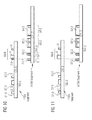
- FIG. 11 In this figure the injection 7 . 0 is now missing in packet G 4 . 0 of the cylinder Cy 10 .
- the method thus features a number of steps that are executed: Computation and grouping of injections into packets (distribution), normalization (adjusting the number) and collision correction, e.g. by shifting injections. This can also take account of requirements, according to which certain injections are not of interest if they were shifted too greatly and should thus rather be omitted.
- FIG. 12 is a schematic of the sequence of the method.
- the grouping or distribution of injections into packets is undertaken in a block 50 , with predetermined variables (e.g. the duration of the injections or pulses and the position of the injection or pulses) being accessed.
- predetermined variables e.g. the duration of the injections or pulses and the position of the injection or pulses
- the possible number of packets and number of injections per packet are adjusted and limited and in block 52 the collisions are corrected, e.g. by shifting injections.
- the data is made available for activation purposes via an interface and a control device (block 53 ) performs the activation of the actuators (block 54 ).
- the method can be advantageously implemented as a computer program.
- the subprocesses could be arranged as subprogram modules.
- the method described above can also be integrated advantageously into an application-specific integrated circuit (ASIC).
- ASIC application-specific integrated circuit
- the network can execute the method in one of its embodiments.
- a computer program has program code means to execute the method in one of its embodiments when the program is executed on a computer or computer network.
- the program code means can be stored on a computer-readable data medium.
- a data medium has a data structure stored which, after it is loaded into a working and/or main memory of a computer or computer network, can execute the method in one of its embodiments.
- a computer program product with program code means stored on a machine-readable medium may execute the method in one of its embodiments if the program is executed on a computer or computer network.
- the term computer program product is to be understood as a marketable product. It can basically be available in any form, for example on paper or a computer-readable medium, and can especially be distributed over a data transmission network.
Landscapes
- Engineering & Computer Science (AREA)
- Chemical & Material Sciences (AREA)
- Combustion & Propulsion (AREA)
- Mechanical Engineering (AREA)
- General Engineering & Computer Science (AREA)
- Electrical Control Of Air Or Fuel Supplied To Internal-Combustion Engine (AREA)
Applications Claiming Priority (4)
| Application Number | Priority Date | Filing Date | Title |
|---|---|---|---|
| DE102007005361 | 2007-02-02 | ||
| DE102007005361A DE102007005361B3 (de) | 2007-02-02 | 2007-02-02 | Vorrichtung und Verfahren zur Steuerung der Kraftstoffeinspritzung |
| DE102007005361.6 | 2007-02-02 | ||
| PCT/EP2008/050969 WO2008092827A1 (de) | 2007-02-02 | 2008-01-28 | Vorrichtung und verfahren zur steuerung der kraftstoffeinspritzung |
Publications (2)
| Publication Number | Publication Date |
|---|---|
| US20100114459A1 US20100114459A1 (en) | 2010-05-06 |
| US8095295B2 true US8095295B2 (en) | 2012-01-10 |
Family
ID=39356641
Family Applications (1)
| Application Number | Title | Priority Date | Filing Date |
|---|---|---|---|
| US12/524,294 Expired - Fee Related US8095295B2 (en) | 2007-02-02 | 2008-01-28 | Device and method for controlling fuel injection |
Country Status (4)
| Country | Link |
|---|---|
| US (1) | US8095295B2 (de) |
| CN (1) | CN101600873B (de) |
| DE (1) | DE102007005361B3 (de) |
| WO (1) | WO2008092827A1 (de) |
Cited By (2)
| Publication number | Priority date | Publication date | Assignee | Title |
|---|---|---|---|---|
| US20120101709A1 (en) * | 2009-06-18 | 2012-04-26 | Martin Brandt | Method and apparatus for operating an internal combustion engine |
| US20130112172A1 (en) * | 2011-11-08 | 2013-05-09 | Hitachi Automotive Systems, Ltd. | Fuel Injection Control Device for Internal Combustion Engine |
Families Citing this family (7)
| Publication number | Priority date | Publication date | Assignee | Title |
|---|---|---|---|---|
| DE102008047384A1 (de) * | 2008-09-16 | 2010-04-15 | Continental Automotive Gmbh | Verfahren zum Definieren oder Vergeben von Einspritz-Zeitabschnitten für Kraftstoffinjektoren, sowie Verfahren zum Ansteuern von Kraftstoffinjektoren |
| DE102009007792B4 (de) | 2009-02-06 | 2016-03-03 | Continental Automotive Gmbh | Verfahren und Vorrichtung zum Betreiben einer Brennkraftmaschine |
| JP5519410B2 (ja) | 2010-06-01 | 2014-06-11 | 本田技研工業株式会社 | 内燃機関の燃料供給装置 |
| JP5400817B2 (ja) * | 2011-01-31 | 2014-01-29 | 本田技研工業株式会社 | 内燃機関の燃料噴射制御装置 |
| DE102016207036B4 (de) | 2016-04-26 | 2018-01-25 | Continental Automotive Gmbh | Verfahren und Vorrichtung zur Steuerung der Kraftstoffeinspritzung bei einer Brennkraftmaschine |
| DE102016217306A1 (de) * | 2016-09-12 | 2018-03-15 | Robert Bosch Gmbh | Verfahren zur Steuerung von Mehrfacheinspritzungen bei einem Einspritzsystem |
| DE102016217308A1 (de) * | 2016-09-12 | 2018-03-15 | Robert Bosch Gmbh | Verfahren zur Steuerung von Mehrfacheinspritzungen bei einem Einspritzsystem |
Citations (14)
| Publication number | Priority date | Publication date | Assignee | Title |
|---|---|---|---|---|
| US3702601A (en) * | 1971-06-11 | 1972-11-14 | Gen Motors Corp | Electronic fuel injection system |
| US4387429A (en) * | 1978-07-21 | 1983-06-07 | Hitachi, Ltd. | Fuel injection system for internal combustion engine |
| US4688536A (en) * | 1985-06-28 | 1987-08-25 | Toyota Jidosha Kabushiki Kaisha | Drive circuit for an electrostrictive actuator in a fuel injection valve |
| US5130598A (en) * | 1990-05-08 | 1992-07-14 | Caterpillar Inc. | Apparatus for driving a piezoelectric actuator |
| US5402760A (en) * | 1992-05-21 | 1995-04-04 | Nippondenso Co., Ltd. | Fuel injection control apparatus for internal combustion engine |
| US5479910A (en) * | 1994-05-04 | 1996-01-02 | Robert Bosch Gmbh | Method and device for controlling an internal combustion engine |
| US6044823A (en) * | 1997-05-22 | 2000-04-04 | Mitsubishi Denki Kabushiki Kaisha | Fuel injector control system for cylinder injection type internal combustion engine |
| DE10033343A1 (de) | 2000-07-08 | 2002-01-17 | Bosch Gmbh Robert | Kraftstoffeinspritzanlage für einen Verbrennungsmotor |
| DE10041448A1 (de) | 2000-08-23 | 2002-03-07 | Bosch Gmbh Robert | Verfahren und Vorrichtung zur Steuerung einer Brennkraftmaschine |
| DE10114039A1 (de) | 2001-03-22 | 2002-09-26 | Bosch Gmbh Robert | Verfahren und Vorrichtung zur Steuerung der Kraftstoffeinspritzung |
| EP1497544A1 (de) | 2002-04-09 | 2005-01-19 | Robert Bosch Gmbh | Verfahren zum betrieb einer kraftstoffeinspritzanlage für einen verbrennungsmotor |
| US6862515B2 (en) * | 2000-10-18 | 2005-03-01 | Robert Bosch Gmbh | Method, computer program and control arrangement for operating an internal combustion engine |
| US20050229898A1 (en) | 2004-04-14 | 2005-10-20 | Denso Corporation | Fuel injection system executing overlap injection operation |
| US7944117B2 (en) * | 2006-04-10 | 2011-05-17 | Renault S.A.S | Device and method for driving an ultrasound piezoelectric actuator |
Family Cites Families (1)
| Publication number | Priority date | Publication date | Assignee | Title |
|---|---|---|---|---|
| JP4148128B2 (ja) * | 2003-12-12 | 2008-09-10 | 株式会社デンソー | 燃料噴射装置 |
-
2007
- 2007-02-02 DE DE102007005361A patent/DE102007005361B3/de active Active
-
2008
- 2008-01-28 WO PCT/EP2008/050969 patent/WO2008092827A1/de active Application Filing
- 2008-01-28 US US12/524,294 patent/US8095295B2/en not_active Expired - Fee Related
- 2008-01-28 CN CN2008800036148A patent/CN101600873B/zh not_active Expired - Fee Related
Patent Citations (18)
| Publication number | Priority date | Publication date | Assignee | Title |
|---|---|---|---|---|
| US3702601A (en) * | 1971-06-11 | 1972-11-14 | Gen Motors Corp | Electronic fuel injection system |
| US4387429A (en) * | 1978-07-21 | 1983-06-07 | Hitachi, Ltd. | Fuel injection system for internal combustion engine |
| US4688536A (en) * | 1985-06-28 | 1987-08-25 | Toyota Jidosha Kabushiki Kaisha | Drive circuit for an electrostrictive actuator in a fuel injection valve |
| US5130598A (en) * | 1990-05-08 | 1992-07-14 | Caterpillar Inc. | Apparatus for driving a piezoelectric actuator |
| US5402760A (en) * | 1992-05-21 | 1995-04-04 | Nippondenso Co., Ltd. | Fuel injection control apparatus for internal combustion engine |
| US5479910A (en) * | 1994-05-04 | 1996-01-02 | Robert Bosch Gmbh | Method and device for controlling an internal combustion engine |
| US6044823A (en) * | 1997-05-22 | 2000-04-04 | Mitsubishi Denki Kabushiki Kaisha | Fuel injector control system for cylinder injection type internal combustion engine |
| US6564771B2 (en) | 2000-07-08 | 2003-05-20 | Robert Bosch Gmbh | Fuel injection system for an internal combustion engine |
| DE10033343A1 (de) | 2000-07-08 | 2002-01-17 | Bosch Gmbh Robert | Kraftstoffeinspritzanlage für einen Verbrennungsmotor |
| US20020046731A1 (en) | 2000-07-08 | 2002-04-25 | Johannes-Jorg Rueger | Fuel injection system for an internal combustion engine |
| DE10041448A1 (de) | 2000-08-23 | 2002-03-07 | Bosch Gmbh Robert | Verfahren und Vorrichtung zur Steuerung einer Brennkraftmaschine |
| US20040030488A1 (en) | 2000-08-23 | 2004-02-12 | Juergen Moessinger | Method and device for controlling an internal combustion engine |
| US6865473B2 (en) | 2000-08-23 | 2005-03-08 | Robert Bosch Gmbh | Method and device for controlling an internal combustion engine |
| US6862515B2 (en) * | 2000-10-18 | 2005-03-01 | Robert Bosch Gmbh | Method, computer program and control arrangement for operating an internal combustion engine |
| DE10114039A1 (de) | 2001-03-22 | 2002-09-26 | Bosch Gmbh Robert | Verfahren und Vorrichtung zur Steuerung der Kraftstoffeinspritzung |
| EP1497544A1 (de) | 2002-04-09 | 2005-01-19 | Robert Bosch Gmbh | Verfahren zum betrieb einer kraftstoffeinspritzanlage für einen verbrennungsmotor |
| US20050229898A1 (en) | 2004-04-14 | 2005-10-20 | Denso Corporation | Fuel injection system executing overlap injection operation |
| US7944117B2 (en) * | 2006-04-10 | 2011-05-17 | Renault S.A.S | Device and method for driving an ultrasound piezoelectric actuator |
Non-Patent Citations (2)
| Title |
|---|
| German Office Action, German application No. 10 2007 005 361.6-26, 3 pages, Jul. 30, 2007. |
| International PCT Search Report, PCT/EP2008/050969, 11 pages, Mailed May 27, 2008. |
Cited By (3)
| Publication number | Priority date | Publication date | Assignee | Title |
|---|---|---|---|---|
| US20120101709A1 (en) * | 2009-06-18 | 2012-04-26 | Martin Brandt | Method and apparatus for operating an internal combustion engine |
| US8812216B2 (en) * | 2009-06-18 | 2014-08-19 | Continental Automotive Gmbh | Method and apparatus for operating an internal combustion engine |
| US20130112172A1 (en) * | 2011-11-08 | 2013-05-09 | Hitachi Automotive Systems, Ltd. | Fuel Injection Control Device for Internal Combustion Engine |
Also Published As
| Publication number | Publication date |
|---|---|
| US20100114459A1 (en) | 2010-05-06 |
| WO2008092827A1 (de) | 2008-08-07 |
| DE102007005361B3 (de) | 2008-10-09 |
| CN101600873A (zh) | 2009-12-09 |
| CN101600873B (zh) | 2013-04-03 |
Similar Documents
| Publication | Publication Date | Title |
|---|---|---|
| US8095295B2 (en) | Device and method for controlling fuel injection | |
| US20070162215A1 (en) | Method for balancing out the differences in the injection quantities between the cylinders in an internal combustion engine | |
| EP2492478A1 (de) | Injektoransteuerschaltung | |
| JPH10510027A (ja) | 内燃機関の制御方法及び装置 | |
| US20110126801A1 (en) | Method and device for operating an internal combustion engine | |
| DE10301298A1 (de) | Einspritzsteuergerät eines Motors für einen zu Benzin alternativen Kraftstoff | |
| JP5746331B2 (ja) | 内燃機関内で燃料を供給する方法及び装置 | |
| US8186204B2 (en) | Method and device for dynamically determining a segment for an angular spread, inside which fuel is injected into an internal combustion engine | |
| US9869263B2 (en) | Method of controlling a solenoid valve | |
| US7027907B2 (en) | Sequence scheduling control for a fuel injected engine | |
| JPH04504453A (ja) | エンジンシリンダに対する燃料供給を減少させる方法 | |
| US20100005785A1 (en) | Method for Reducing Emissions in a Motor Vehicle by Controlling the Generator Output | |
| US11118554B2 (en) | Internal combustion engine and control of the energization to an ignition coil and energization to an injector | |
| US20180080358A1 (en) | Fuel Apportionment Strategy for In-Cylinder Dosing | |
| CN106133298B (zh) | 将燃料喷射到内燃发动机中的方法 | |
| US20160069311A1 (en) | Injector drive device | |
| CN102803690B (zh) | 用于操作内燃机的方法和设备 | |
| KR20010039696A (ko) | 내연기관의 연료분사 제어장치 | |
| US11852095B2 (en) | Method for dividing a fuel injection | |
| JP5093050B2 (ja) | 直噴火花点火式エンジンの燃料噴射制御装置 | |
| US11840977B2 (en) | Method of controlling fuel injection after cranking | |
| US11982244B1 (en) | System and method for in-cylinder dosing (ICD) for an engine | |
| AU2012211828B2 (en) | Fuel injection control device | |
| DE102013214828A1 (de) | Verfahren zum Betrieb eines Einspritzsystems einer dreizylindrigen Brennkraftmaschine, insbesondere eines Kraftfahrzeugs | |
| JP2000027697A (ja) | 内燃機関の燃料噴射制御方法 |
Legal Events
| Date | Code | Title | Description |
|---|---|---|---|
| AS | Assignment |
Owner name: CONTINENTAL AUTOMOTIVE GMBH,GERMANY Free format text: ASSIGNMENT OF ASSIGNORS INTEREST;ASSIGNORS:ENGELMANN, JOACHIM, DR.;GRACIANO, JOAO;SIGNING DATES FROM 20090706 TO 20090720;REEL/FRAME:023007/0233 Owner name: CONTINENTAL AUTOMOTIVE GMBH,GERMANY Free format text: ASSIGNMENT OF ASSIGNORS INTEREST;ASSIGNOR:VALERO-BERTRAND, DIEGO;REEL/FRAME:023007/0270 Effective date: 20090709 Owner name: CONTINENTAL AUTOMOTIVE GMBH, GERMANY Free format text: ASSIGNMENT OF ASSIGNORS INTEREST;ASSIGNOR:VALERO-BERTRAND, DIEGO;REEL/FRAME:023007/0270 Effective date: 20090709 Owner name: CONTINENTAL AUTOMOTIVE GMBH, GERMANY Free format text: ASSIGNMENT OF ASSIGNORS INTEREST;ASSIGNORS:ENGELMANN, JOACHIM, DR.;GRACIANO, JOAO;SIGNING DATES FROM 20090706 TO 20090720;REEL/FRAME:023007/0233 |
|
| FEPP | Fee payment procedure |
Free format text: PAYOR NUMBER ASSIGNED (ORIGINAL EVENT CODE: ASPN); ENTITY STATUS OF PATENT OWNER: LARGE ENTITY |
|
| STCF | Information on status: patent grant |
Free format text: PATENTED CASE |
|
| FPAY | Fee payment |
Year of fee payment: 4 |
|
| FEPP | Fee payment procedure |
Free format text: MAINTENANCE FEE REMINDER MAILED (ORIGINAL EVENT CODE: REM.); ENTITY STATUS OF PATENT OWNER: LARGE ENTITY |
|
| LAPS | Lapse for failure to pay maintenance fees |
Free format text: PATENT EXPIRED FOR FAILURE TO PAY MAINTENANCE FEES (ORIGINAL EVENT CODE: EXP.); ENTITY STATUS OF PATENT OWNER: LARGE ENTITY |
|
| STCH | Information on status: patent discontinuation |
Free format text: PATENT EXPIRED DUE TO NONPAYMENT OF MAINTENANCE FEES UNDER 37 CFR 1.362 |
|
| FP | Lapsed due to failure to pay maintenance fee |
Effective date: 20200110 |