US8071014B2 - Apparatus and method for closing or opening an opening, especially a bottom opening of a material hopper for a blast furnace, and blast furnace having such an apparatus - Google Patents
Apparatus and method for closing or opening an opening, especially a bottom opening of a material hopper for a blast furnace, and blast furnace having such an apparatus Download PDFInfo
- Publication number
- US8071014B2 US8071014B2 US12/134,623 US13462308A US8071014B2 US 8071014 B2 US8071014 B2 US 8071014B2 US 13462308 A US13462308 A US 13462308A US 8071014 B2 US8071014 B2 US 8071014B2
- Authority
- US
- United States
- Prior art keywords
- opening
- rotation
- flap plate
- plate
- lever
- Prior art date
- Legal status (The legal status is an assumption and is not a legal conclusion. Google has not performed a legal analysis and makes no representation as to the accuracy of the status listed.)
- Expired - Fee Related, expires
Links
Images


Classifications
-
- C—CHEMISTRY; METALLURGY
- C21—METALLURGY OF IRON
- C21B—MANUFACTURE OF IRON OR STEEL
- C21B7/00—Blast furnaces
-
- F—MECHANICAL ENGINEERING; LIGHTING; HEATING; WEAPONS; BLASTING
- F27—FURNACES; KILNS; OVENS; RETORTS
- F27B—FURNACES, KILNS, OVENS OR RETORTS IN GENERAL; OPEN SINTERING OR LIKE APPARATUS
- F27B1/00—Shaft or like vertical or substantially vertical furnaces
- F27B1/10—Details, accessories or equipment specially adapted for furnaces of these types
- F27B1/20—Arrangements of devices for charging
-
- C—CHEMISTRY; METALLURGY
- C21—METALLURGY OF IRON
- C21B—MANUFACTURE OF IRON OR STEEL
- C21B7/00—Blast furnaces
- C21B7/18—Bell-and-hopper arrangements
-
- C—CHEMISTRY; METALLURGY
- C21—METALLURGY OF IRON
- C21B—MANUFACTURE OF IRON OR STEEL
- C21B7/00—Blast furnaces
- C21B7/18—Bell-and-hopper arrangements
- C21B7/20—Bell-and-hopper arrangements with appliances for distributing the burden
-
- F—MECHANICAL ENGINEERING; LIGHTING; HEATING; WEAPONS; BLASTING
- F27—FURNACES; KILNS; OVENS; RETORTS
- F27D—DETAILS OR ACCESSORIES OF FURNACES, KILNS, OVENS OR RETORTS, IN SO FAR AS THEY ARE OF KINDS OCCURRING IN MORE THAN ONE KIND OF FURNACE
- F27D3/00—Charging; Discharging; Manipulation of charge
- F27D3/10—Charging directly from hoppers or shoots
- F27D2003/105—Charging directly from hoppers or shoots using shutters
Definitions
- Embodiments of the present invention relate to an apparatus and method for closing or opening an opening, especially a bottom opening of a material hopper for a blast furnace, and a blast furnace having such an apparatus.
- DE 103 27 276 A1 discloses an apparatus including a shut-off flap valve or furnace mouth flap valve, which is used to control the charging of a blast furnace with coke and burden material.
- the apparatus includes a flap plate which, for the purpose of closing or opening the bottom opening of a material hopper arranged above the mouth of a blast furnace, is movable into an open position and into a closed position.
- a drive mechanism is usually in articulated connection at the flap rim, by which it is ensured that, in the open position, the flap plate leaves the flow opening substantially completely clear.
- the flap plate is pivoted out relatively far away from the opening, so that the mouth of the blast furnace has to be correspondingly dimensioned in order to avoid a collision of the flap plate with loose material.
- One goal of the embodiments of the invention is to improve a closure apparatus so that low-maintenance operation is made possible in a simple manner, and to avoid premature wear on the sealing system. Another goal is furthermore to provide a blast furnace having such an apparatus and a method of closing or opening an opening, especially a bottom opening of a material hopper arranged above the mouth of a blast furnace.
- An apparatus for closing or opening an opening, especially a bottom opening of a material hopper arranged above the mouth of a blast furnace having a drivable flap plate, which is movable into an open position leaving the opening clear and into a closed position blocking off the opening and vice-versa.
- the flap plate is connected to a linkage arrangement in such away that the flap plate carries out, in the region of the opening, a linear movement substantially perpendicular to the plane of the opening and, distal to the opening, a pivoting movement.
- the pivoting movement of the flap plate includes, at least in the region of overlap of the flap plate with the opening, a translational movement parallel to the plane of the opening, on which there is superimposed a rotational movement.
- a translational movement parallel to the plane of the opening on which there is superimposed a rotational movement.
- the linkage arrangement includes a four-bar linkage, which couples the flap plate to a drive.
- a linkage arrangement of such a kind makes possible, in constructionally simple and robust manner, the linear movement of the flap plate in the region of the opening and also the pivoting movement distal to the opening.
- the linkage arrangement can include an actuation lever and a plate lever, which have axes of rotation arranged in a fixed position and spaced apart from one another.
- the actuation lever and the plate lever can be coupled together by a first rotation joint.
- the plate lever can have a first arm, rigidly connected to the flap plate, and a second arm, rotatably mounted on one of the axes of rotation, the first arm and the second arm being coupled together by a second rotation joint.
- a linkage arrangement of such a kind results in a compact mode of construction, which makes it possible for the flap plate to be pressed down onto or lifted off from the sealing seat of the opening in substantially frictionless manner.
- a relatively high application pressure is achieved with, at the same time, a low drive moment, resulting in improved sealing of the arrangement
- the first and second rotation joints are, in the closed position, arranged on a common vertical axis.
- the fixed-position axes of rotation can be arranged offset, relative to a vertical axis.
- the axis of rotation of the plate lever can be arranged closer than the axis of rotation of the actuation lever to a central axis of the opening.
- the offset arrangement of the axes of rotation results in different pivoting radii for the two levers so that an optimized movement path of the flap plate close to the housing of the opening, or of the material hopper, is brought about in a simple manner.
- the first and second rotation joints can be movable on different pivoting paths, the rotation joints being spaced further apart from one another in the open position than in the closed position. This too ensures that, distal to the opening, the flap plate performs a movement that is guided close to the housing of the opening, whilst in the proximity of the opening or in the region of the opening a linear movement of the flap plate is accomplished.
- Such an apparatus is also provided in the context of a blast furnace, as well as a method of closing or opening the opening, especially a bottom opening of a material hopper arranged above the mouth of a blast furnace.
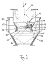
- FIG. 1 is a cross-section through an apparatus according to an example of an embodiment according to the invention with a flap plate in the closed position;
- FIG. 2 shows the apparatus according to FIG. 1 with the flap plate in the open position
- FIG. 3 shows an apparatus according to FIG. 1 , with the movement sequence of the flap plate and of the associated lever mechanism being shown in discrete steps;
- FIG. 4 shows the apparatus according to FIG. 1 in a section perpendicular to the section shown in FIG. 1 .
- FIGS. 1-4 show a furnace mouth flap valve having a flap plate 12 , which is intended for closing or opening a bottom opening 10 of a material hopper 11 arranged above the mouth of a blast furnace.
- a flap plate 12 As a result of opening the flap plate 12 , loose material, especially ores and burden material, is directed into the mouth of the blast furnace through the bottom opening 10 ( FIG. 2 ).
- the bottom opening 10 In the closed position, the bottom opening 10 is closed off in gas-tight manner by the flap plate 12 ( FIG. 1 ).
- the bottom opening 10 is arranged at the underneath of a funnel 23 , which is connected to the material hopper 11 .
- a sealing seat 24 having sealing elements.
- a corresponding circumferential sealing surface 25 on the flap rim of the flap plate 12 there is provided a corresponding circumferential sealing surface 25 , which in the closed position of the flap plate 12 co-operates with the sealing seat 24 to provide sealing.
- the flap plate 12 is movable into a closed position ( FIG. 1 ) and into an open position ( FIG. 2 ), the flap plate 12 in the open position being arranged in a space between the funnel 23 and the housing 26 of the furnace mouth and, therefore, outside the fluid flow.
- the flap plate 12 For the movement of the flap plate 12 into the open position and into the closed position and vice-versa the flap plate is connected to a linkage arrangement 13 .
- the linkage arrangement 13 therein is so adapted that the flap plate 12 carries out, in the region of the bottom opening 10 , a linear movement substantially perpendicular to the plane of the opening and, distal to the bottom opening 10 , a pivoting movement.
- the pivoting movement can be seen especially in FIG. 3 .
- the flap plate 12 is therefore moved plane-parallel to the plane of the opening, that is to say to the plane passing through the bottom opening 10 . Only then, that is to say when there is no contact between the flap plate 12 and the sealing seat 24 and any relative movements across the flow direction S are non-critical, is the flap plate 12 pivoted to the side and moved into the intermediate space between the funnel 23 and the furnace mouth housing 26 .
- the linkage arrangement 13 includes a four-bar linkage, or four-member rotation joint linkage. This makes it possible for the linkage arrangement to be constructed in especially compact and robust manner.
- the plate lever 16 is of U-shaped construction and passes underneath the flap plate 12 .
- the plate lever 16 is fixedly connected to the flap plate 12 and forms a rigid unit with the latter. In this arrangement, the plate lever 16 engages the flap plate 12 centrally, as a result of which centered introduction of the application force into the flap plate 12 and accordingly a uniform application pressure is achieved.
- the actuation lever 15 and the plate lever 16 are in each case rotatably mounted on axes of rotation 17 , 18 arranged in a fixed position.
- the axes of rotation 17 , 18 are disposed spaced apart from one another, the axis of rotation 18 of the plate lever 16 being provided below the axis of rotation 17 of the actuation lever 15 .
- the two axes of rotation 17 , 18 are furthermore arranged offset from one another, more specifically in relation to a vertical axis, the axis of rotation 18 of the plate lever 16 being arranged closer than the axis of rotation 17 of the actuation lever 15 to the center-line M of the bottom opening 10 .
- the actuation lever 15 has a first rotation joint 19 , which in the closed position is arranged at the same height as the axis of rotation 17 of the actuation lever 15 .
- the rotation joint 19 and the axis of rotation 17 are in each case arranged in the region of the shorter leg of the L-shaped portion of the actuation lever 15 .
- the rotation joint 19 is arranged on the center-line M of the funnel 23 and bottom opening 10 .
- the rotation joint 19 forms an articulated connection between the actuation lever 15 and the plate lever 16 .
- the short leg of the L-shaped cranked actuation lever 15 would in itself be sufficient.
- connection of the two L-shaped parts of the actuation lever 15 on both sides of the bottom opening 10 and therefore the combined U-L shape of the actuation lever 15 is advantageous.
- the drive 14 it is possible, as shown in FIG. 4 , for the drive 14 to be provided on only one side of the linkage arrangement 13 .
- the plate lever 16 has a first arm 20 and a second arm 21 , the first arm 20 being rigidly connected to the flap plate 12 .
- the first arm 20 is of U-shaped construction, as shown in FIG. 4 , and on both sides of the bottom opening 10 is coupled in articulated manner to the second arm 21 by a second rotation joint 22 .
- the second arm is mounted in rotatable manner and connected to the housing.
- the linkage arrangement 13 shown in FIG. 1 results in the fact that the second arm 21 , mounted on the fixed-position axis of rotation 18 , of opposite plate lever 16 is shorter than the short leg (which in the closed position according to FIG. 1 is arranged parallel thereto) of the L-shaped portion of the actuation lever 15 .
- FIG. 3 shows the spatial movement sequence of the flap plate 12 and of the associated lever mechanism in discrete steps, the end points of the movement being defined by the closed position of the flap plate 12 on the one hand ( FIG. 1 ) and its open position on the other hand ( FIG. 2 ).
- the actuation lever 15 or the longer leg of the L-shaped portion of the actuation lever 15 , is initially arranged behind the plate lever 16 in the pivoting direction, that is to say the former runs behind the latter. Whilst the flap plate 12 is still located in the region of overlap with the bottom opening 10 , the actuation lever 15 overtakes the plate lever 16 until the actuation lever 15 has performed about half the pivoting movement. Then the plate lever 16 overtakes the actuation lever 15 until the end position, that is to say the open position of the flap plate 12 , has been reached. In the open position according to FIG. 2 , the actuation lever 15 and the plate lever 16 re-assume the original arrangement relative to one another, wherein the actuation lever 15 is arranged behind the plate lever 16 in the pivoting direction (from the closed position to the open position).
Landscapes
- Engineering & Computer Science (AREA)
- Chemical & Material Sciences (AREA)
- Metallurgy (AREA)
- Manufacturing & Machinery (AREA)
- General Engineering & Computer Science (AREA)
- Materials Engineering (AREA)
- Mechanical Engineering (AREA)
- Organic Chemistry (AREA)
- Blast Furnaces (AREA)
- Vertical, Hearth, Or Arc Furnaces (AREA)
- Filling Or Emptying Of Bunkers, Hoppers, And Tanks (AREA)
- Furnace Charging Or Discharging (AREA)
- Lift Valve (AREA)
- Mechanically-Actuated Valves (AREA)
Applications Claiming Priority (3)
| Application Number | Priority Date | Filing Date | Title |
|---|---|---|---|
| DE102007026509A DE102007026509A1 (de) | 2007-06-08 | 2007-06-08 | Vorrichtung und Verfahren zum Verschließen oder Öffnen einer Öffnung, insbesondere Bodenöffnung eines Materialbunkers für einen Hochofen und Hochofen mit einer derartigen Vorrichtung |
| DE102007026509 | 2007-06-08 | ||
| DE102007026509.5 | 2007-06-08 |
Publications (2)
| Publication Number | Publication Date |
|---|---|
| US20080302796A1 US20080302796A1 (en) | 2008-12-11 |
| US8071014B2 true US8071014B2 (en) | 2011-12-06 |
Family
ID=39870594
Family Applications (1)
| Application Number | Title | Priority Date | Filing Date |
|---|---|---|---|
| US12/134,623 Expired - Fee Related US8071014B2 (en) | 2007-06-08 | 2008-06-06 | Apparatus and method for closing or opening an opening, especially a bottom opening of a material hopper for a blast furnace, and blast furnace having such an apparatus |
Country Status (10)
| Country | Link |
|---|---|
| US (1) | US8071014B2 (de) |
| EP (1) | EP2000547B1 (de) |
| JP (1) | JP5612812B2 (de) |
| KR (1) | KR101507918B1 (de) |
| CN (1) | CN101319255A (de) |
| BR (1) | BRPI0803002B1 (de) |
| CA (1) | CA2633670C (de) |
| DE (1) | DE102007026509A1 (de) |
| RU (1) | RU2466191C2 (de) |
| UA (1) | UA100838C2 (de) |
Cited By (1)
| Publication number | Priority date | Publication date | Assignee | Title |
|---|---|---|---|---|
| US11498712B2 (en) * | 2018-01-11 | 2022-11-15 | Windmöller & Hölscher Kg | Filling device and method for filling upwardly open packaging containers, and form-fill-seal device |
Families Citing this family (9)
| Publication number | Priority date | Publication date | Assignee | Title |
|---|---|---|---|---|
| DE102007026509A1 (de) * | 2007-06-08 | 2008-12-11 | Z & J Technologies Gmbh | Vorrichtung und Verfahren zum Verschließen oder Öffnen einer Öffnung, insbesondere Bodenöffnung eines Materialbunkers für einen Hochofen und Hochofen mit einer derartigen Vorrichtung |
| LU91583B1 (en) | 2009-07-03 | 2011-01-04 | Wurth Paul Sa | Sealing valve arrangement for a shaft furnace charging installation |
| CN103072766A (zh) * | 2013-01-09 | 2013-05-01 | 河南陆德筑机股份有限公司 | 一种防卡阻放料门 |
| CA2931946C (en) * | 2013-12-23 | 2022-05-03 | Bayer Cropscience Lp | Bin outlet inserts, and bin assembly systems and method employing such inserts |
| DE102015116195B4 (de) | 2015-09-24 | 2020-11-19 | TDCo GmbH | Dichtklappe für einen Gichtverschluss |
| LU93298B1 (en) * | 2016-11-10 | 2018-06-13 | Wurth Paul Sa | Sealing Valve Arrangement For A Shaft Furnace Charging Installation |
| DE102017106809A1 (de) * | 2017-03-29 | 2018-10-04 | TDCo GmbH | Neue Dichtklappe für einen Gichtverschluss |
| CN115231143B (zh) * | 2022-07-11 | 2023-10-03 | 韩亚半导体材料(贵溪)有限公司 | 一种具有密封性的配氨罐 |
| CN117284796B (zh) * | 2023-11-23 | 2024-01-30 | 四川朗晟新能源科技有限公司 | 一种匣钵倒料翻转装置 |
Citations (10)
| Publication number | Priority date | Publication date | Assignee | Title |
|---|---|---|---|---|
| DE613328C (de) | 1935-05-17 | Fried Krupp Grusonwerk Akt Ges | Abschlussvorrichtung zum Schliessen einer in geneigter Ebene liegenden OEffnung | |
| US3704992A (en) * | 1970-03-05 | 1972-12-05 | Demag Ag | Charging apparatus construction for a blast furnace |
| BE849156A (fr) | 1976-12-08 | 1977-04-01 | Systeme a gueulard pour fours a cuve metallurgiques | |
| US4844292A (en) * | 1987-03-24 | 1989-07-04 | Paul Wurth S.A. | Mechanism for actuating an opening and shut-off valve |
| US5285811A (en) * | 1992-07-16 | 1994-02-15 | Trinity Industries, Inc. | Hopper gate valve |
| EP0997698A1 (de) | 1998-10-30 | 2000-05-03 | Paul Wurth S.A. | Gutabsperrklappe für einen Fülltrichter |
| US6543747B2 (en) * | 1999-11-30 | 2003-04-08 | Henry Pratt Company | Valve actuator apparatus |
| US6792973B2 (en) * | 2000-05-30 | 2004-09-21 | Paul Wurth S.A. | Gas tight shut off valve for a material charging or discharging lock |
| DE10327276A1 (de) | 2003-06-17 | 2005-01-05 | Z & J Technologies Gmbh | Vorrichtung zum Verschließen oder Öffnen einer Öffnung, insbesondere Bodenöffnung eines Materialbunkers für einen Hochofen |
| US6897412B1 (en) * | 2004-01-27 | 2005-05-24 | Agilent Technologies, Inc. | Inward opening oven intake for gas chromatographic oven |
Family Cites Families (13)
| Publication number | Priority date | Publication date | Assignee | Title |
|---|---|---|---|---|
| JPS6028670Y2 (ja) * | 1980-11-06 | 1985-08-30 | 石川島播磨重工業株式会社 | 高炉炉頂装入装置用原料分配装置 |
| RU2017827C1 (ru) * | 1991-12-10 | 1994-08-15 | Мариупольский концерн "Азовмаш" | Уплотнительный клапан загрузочного устройства доменной печи |
| LU88231A1 (fr) * | 1993-03-04 | 1994-10-03 | Wurth Paul Sa | Dispositif de chargement avec organe de réglage du débit |
| RU2100444C1 (ru) * | 1996-06-20 | 1997-12-27 | Акционерное общество "Гипромез" | Газоуплотнительный клапан загрузочного устройства доменной печи |
| JPH10339582A (ja) * | 1997-06-05 | 1998-12-22 | Ishikawajima Harima Heavy Ind Co Ltd | 原料予熱槽の頂部開閉ゲート装置 |
| JPH11210924A (ja) * | 1998-01-28 | 1999-08-06 | Junten Engineering:Kk | リンク機構を備えた弁装置 |
| JP2000337546A (ja) * | 1999-05-28 | 2000-12-05 | Tokyo Electron Ltd | ゲートバルブ |
| LU90452B1 (fr) * | 1999-09-27 | 2001-03-28 | Wurth Paul Sa | Dispositif d'-tanch-it- |
| JP4659167B2 (ja) * | 1999-11-24 | 2011-03-30 | 正俊 今中 | ホッパ装置 |
| RU2164950C1 (ru) * | 2000-08-04 | 2001-04-10 | Закрытое акционерное общество "Научно-производственный и коммерческий центр "ТОТЕМ" | Газоуплотнительный клапан загрузочного устройства доменной печи |
| JP3840088B2 (ja) * | 2001-10-23 | 2006-11-01 | 株式会社松井製作所 | 粉粒体用の開閉弁装置 |
| JP3116436U (ja) * | 2005-08-19 | 2005-12-08 | 株式会社エイシン | ホッパ下部に取り付けられるスイング式開閉弁 |
| DE102007026509A1 (de) * | 2007-06-08 | 2008-12-11 | Z & J Technologies Gmbh | Vorrichtung und Verfahren zum Verschließen oder Öffnen einer Öffnung, insbesondere Bodenöffnung eines Materialbunkers für einen Hochofen und Hochofen mit einer derartigen Vorrichtung |
-
2007
- 2007-06-08 DE DE102007026509A patent/DE102007026509A1/de not_active Withdrawn
-
2008
- 2008-05-29 EP EP08157147.3A patent/EP2000547B1/de not_active Not-in-force
- 2008-06-05 CA CA2633670A patent/CA2633670C/en not_active Expired - Fee Related
- 2008-06-06 US US12/134,623 patent/US8071014B2/en not_active Expired - Fee Related
- 2008-06-06 CN CNA2008100986833A patent/CN101319255A/zh active Pending
- 2008-06-07 RU RU2008122707/02A patent/RU2466191C2/ru not_active IP Right Cessation
- 2008-06-09 BR BRPI0803002A patent/BRPI0803002B1/pt not_active IP Right Cessation
- 2008-06-09 UA UAA200807829A patent/UA100838C2/uk unknown
- 2008-06-09 KR KR20080053580A patent/KR101507918B1/ko not_active Expired - Fee Related
- 2008-06-09 JP JP2008150265A patent/JP5612812B2/ja not_active Expired - Fee Related
Patent Citations (11)
| Publication number | Priority date | Publication date | Assignee | Title |
|---|---|---|---|---|
| DE613328C (de) | 1935-05-17 | Fried Krupp Grusonwerk Akt Ges | Abschlussvorrichtung zum Schliessen einer in geneigter Ebene liegenden OEffnung | |
| US3704992A (en) * | 1970-03-05 | 1972-12-05 | Demag Ag | Charging apparatus construction for a blast furnace |
| BE849156A (fr) | 1976-12-08 | 1977-04-01 | Systeme a gueulard pour fours a cuve metallurgiques | |
| US4844292A (en) * | 1987-03-24 | 1989-07-04 | Paul Wurth S.A. | Mechanism for actuating an opening and shut-off valve |
| US5285811A (en) * | 1992-07-16 | 1994-02-15 | Trinity Industries, Inc. | Hopper gate valve |
| EP0997698A1 (de) | 1998-10-30 | 2000-05-03 | Paul Wurth S.A. | Gutabsperrklappe für einen Fülltrichter |
| US6543747B2 (en) * | 1999-11-30 | 2003-04-08 | Henry Pratt Company | Valve actuator apparatus |
| US6792973B2 (en) * | 2000-05-30 | 2004-09-21 | Paul Wurth S.A. | Gas tight shut off valve for a material charging or discharging lock |
| DE10327276A1 (de) | 2003-06-17 | 2005-01-05 | Z & J Technologies Gmbh | Vorrichtung zum Verschließen oder Öffnen einer Öffnung, insbesondere Bodenöffnung eines Materialbunkers für einen Hochofen |
| US7156371B2 (en) | 2003-06-17 | 2007-01-02 | Z&J Technologies Gmbh | Device for opening or closing an opening, in particular a bottom opening of a material bunker for a blast furnace |
| US6897412B1 (en) * | 2004-01-27 | 2005-05-24 | Agilent Technologies, Inc. | Inward opening oven intake for gas chromatographic oven |
Cited By (1)
| Publication number | Priority date | Publication date | Assignee | Title |
|---|---|---|---|---|
| US11498712B2 (en) * | 2018-01-11 | 2022-11-15 | Windmöller & Hölscher Kg | Filling device and method for filling upwardly open packaging containers, and form-fill-seal device |
Also Published As
| Publication number | Publication date |
|---|---|
| JP5612812B2 (ja) | 2014-10-22 |
| JP2008308338A (ja) | 2008-12-25 |
| EP2000547A3 (de) | 2008-12-17 |
| KR101507918B1 (ko) | 2015-04-03 |
| UA100838C2 (uk) | 2013-02-11 |
| CN101319255A (zh) | 2008-12-10 |
| CA2633670C (en) | 2016-02-16 |
| RU2466191C2 (ru) | 2012-11-10 |
| RU2008122707A (ru) | 2009-12-20 |
| BRPI0803002A2 (pt) | 2010-06-15 |
| US20080302796A1 (en) | 2008-12-11 |
| BRPI0803002B1 (pt) | 2015-09-08 |
| EP2000547A2 (de) | 2008-12-10 |
| DE102007026509A1 (de) | 2008-12-11 |
| EP2000547B1 (de) | 2015-03-11 |
| KR20080108058A (ko) | 2008-12-11 |
| CA2633670A1 (en) | 2008-12-08 |
Similar Documents
| Publication | Publication Date | Title |
|---|---|---|
| US8071014B2 (en) | Apparatus and method for closing or opening an opening, especially a bottom opening of a material hopper for a blast furnace, and blast furnace having such an apparatus | |
| US8424843B2 (en) | Shuttle valve having two drives | |
| KR101702830B1 (ko) | 고로 장입 설비를 위한 실링 밸브 장치 | |
| CA1039258A (en) | Swing valve | |
| EP1106879B1 (de) | Drehbarer Schieber | |
| KR20120016030A (ko) | 웨이스트 게이트 또는 가변 터빈 구조 장치용 액츄에이터 및 가변 터빈 구조 장치용 액츄에이터의 용도 | |
| US20110135425A1 (en) | Charging installation for a shaft furnace and lower sealing valve assembly therefore | |
| EP2263896B1 (de) | Offene Dachkonstruktion für ein Fahrzeug | |
| MX2010012779A (es) | Puerta deslizante para un vehiculo. | |
| CA2555072A1 (en) | A surface sweeping machine with a dump door and chute actuating mechanism | |
| WO2020053397A1 (en) | A top charging apparatus for charging material in a blast furnace and a method for opening and closing a bottom opening of a hopper of a blast furnace top charging apparatus | |
| US12103070B2 (en) | Slide gate on the spout of a metallurgical vessel | |
| KR890001075B1 (ko) | 용기배출구로 부터의 용융금속 흐름을 제어하기 위한 밸브기구 | |
| US4457459A (en) | Valve suitable for controlling teeming from furnace tapholes | |
| JPH08257724A (ja) | インゴット加熱装置の下扉機構 |
Legal Events
| Date | Code | Title | Description |
|---|---|---|---|
| AS | Assignment |
Owner name: Z & J TECHNOLOGIES GMBH, GERMANY Free format text: ASSIGNMENT OF ASSIGNORS INTEREST;ASSIGNOR:IRNICH, FRANZ-JOSEF;REEL/FRAME:021408/0062 Effective date: 20080702 |
|
| STCF | Information on status: patent grant |
Free format text: PATENTED CASE |
|
| FPAY | Fee payment |
Year of fee payment: 4 |
|
| SULP | Surcharge for late payment | ||
| FEPP | Fee payment procedure |
Free format text: MAINTENANCE FEE REMINDER MAILED (ORIGINAL EVENT CODE: REM.); ENTITY STATUS OF PATENT OWNER: LARGE ENTITY |
|
| LAPS | Lapse for failure to pay maintenance fees |
Free format text: PATENT EXPIRED FOR FAILURE TO PAY MAINTENANCE FEES (ORIGINAL EVENT CODE: EXP.); ENTITY STATUS OF PATENT OWNER: LARGE ENTITY |
|
| STCH | Information on status: patent discontinuation |
Free format text: PATENT EXPIRED DUE TO NONPAYMENT OF MAINTENANCE FEES UNDER 37 CFR 1.362 |
|
| FP | Lapsed due to failure to pay maintenance fee |
Effective date: 20191206 |