US8023273B2 - Electric device having a plastic plug part arranged on a circuit support - Google Patents
Electric device having a plastic plug part arranged on a circuit support Download PDFInfo
- Publication number
- US8023273B2 US8023273B2 US12/224,634 US22463407A US8023273B2 US 8023273 B2 US8023273 B2 US 8023273B2 US 22463407 A US22463407 A US 22463407A US 8023273 B2 US8023273 B2 US 8023273B2
- Authority
- US
- United States
- Prior art keywords
- plug part
- plastic plug
- rivet
- circuit support
- electric device
- Prior art date
- Legal status (The legal status is an assumption and is not a legal conclusion. Google has not performed a legal analysis and makes no representation as to the accuracy of the status listed.)
- Expired - Fee Related, expires
Links
Images


Classifications
-
- H—ELECTRICITY
- H05—ELECTRIC TECHNIQUES NOT OTHERWISE PROVIDED FOR
- H05K—PRINTED CIRCUITS; CASINGS OR CONSTRUCTIONAL DETAILS OF ELECTRIC APPARATUS; MANUFACTURE OF ASSEMBLAGES OF ELECTRICAL COMPONENTS
- H05K5/00—Casings, cabinets or drawers for electric apparatus
- H05K5/0026—Casings, cabinets or drawers for electric apparatus provided with connectors and printed circuit boards [PCB], e.g. automotive electronic control units
- H05K5/0047—Casings, cabinets or drawers for electric apparatus provided with connectors and printed circuit boards [PCB], e.g. automotive electronic control units having a two-part housing enclosing a PCB
- H05K5/006—Casings, cabinets or drawers for electric apparatus provided with connectors and printed circuit boards [PCB], e.g. automotive electronic control units having a two-part housing enclosing a PCB characterized by features for holding the PCB within the housing
-
- H—ELECTRICITY
- H01—ELECTRIC ELEMENTS
- H01R—ELECTRICALLY-CONDUCTIVE CONNECTIONS; STRUCTURAL ASSOCIATIONS OF A PLURALITY OF MUTUALLY-INSULATED ELECTRICAL CONNECTING ELEMENTS; COUPLING DEVICES; CURRENT COLLECTORS
- H01R12/00—Structural associations of a plurality of mutually-insulated electrical connecting elements, specially adapted for printed circuits, e.g. printed circuit boards [PCB], flat or ribbon cables, or like generally planar structures, e.g. terminal strips, terminal blocks; Coupling devices specially adapted for printed circuits, flat or ribbon cables, or like generally planar structures; Terminals specially adapted for contact with, or insertion into, printed circuits, flat or ribbon cables, or like generally planar structures
- H01R12/70—Coupling devices
- H01R12/71—Coupling devices for rigid printing circuits or like structures
- H01R12/72—Coupling devices for rigid printing circuits or like structures coupling with the edge of the rigid printed circuits or like structures
- H01R12/722—Coupling devices for rigid printing circuits or like structures coupling with the edge of the rigid printed circuits or like structures coupling devices mounted on the edge of the printed circuits
- H01R12/724—Coupling devices for rigid printing circuits or like structures coupling with the edge of the rigid printed circuits or like structures coupling devices mounted on the edge of the printed circuits containing contact members forming a right angle
-
- H—ELECTRICITY
- H05—ELECTRIC TECHNIQUES NOT OTHERWISE PROVIDED FOR
- H05K—PRINTED CIRCUITS; CASINGS OR CONSTRUCTIONAL DETAILS OF ELECTRIC APPARATUS; MANUFACTURE OF ASSEMBLAGES OF ELECTRICAL COMPONENTS
- H05K5/00—Casings, cabinets or drawers for electric apparatus
- H05K5/0026—Casings, cabinets or drawers for electric apparatus provided with connectors and printed circuit boards [PCB], e.g. automotive electronic control units
- H05K5/0069—Casings, cabinets or drawers for electric apparatus provided with connectors and printed circuit boards [PCB], e.g. automotive electronic control units having connector relating features for connecting the connector pins with the PCB or for mounting the connector body with the housing
-
- H—ELECTRICITY
- H05—ELECTRIC TECHNIQUES NOT OTHERWISE PROVIDED FOR
- H05K—PRINTED CIRCUITS; CASINGS OR CONSTRUCTIONAL DETAILS OF ELECTRIC APPARATUS; MANUFACTURE OF ASSEMBLAGES OF ELECTRICAL COMPONENTS
- H05K5/00—Casings, cabinets or drawers for electric apparatus
- H05K5/0026—Casings, cabinets or drawers for electric apparatus provided with connectors and printed circuit boards [PCB], e.g. automotive electronic control units
- H05K5/0082—Casings, cabinets or drawers for electric apparatus provided with connectors and printed circuit boards [PCB], e.g. automotive electronic control units specially adapted for transmission control units, e.g. gearbox controllers
Definitions
- the invention relates to an electric device, in particular a control device for a motor vehicle, having a plate-shaped circuit support that is fastened to a metallic housing baseplate and on which on a side facing away from the housing baseplate is arranged a plastic plug part.
- Electric devices employed in motor-vehicle engineering for example for controlling a gear consist mostly of a plate-shaped circuit support accommodated in a housing and fastened to a housing baseplate.
- a cable is connected via a plastic plug part led through a duct in the housing.
- the plastic plug part's electric contacts are connected to printed conductors on the circuit support.
- Electric devices employed in a motor vehicle are exposed to harsh ambient conditions. High acceleration forces can occur during operation. Connected cables therein transmit vibrations to the solder connections inside the housing via the plug part. Even slight alternating stresses on said solder connections can severely affect the electronic device's reliability. It is consequently endeavored to keep the mechanical stresses introduced by a connecting cable as far away as possible from electric connections, solder connections, and pc-board plug-in connections, meaning that the mechanical connection between the plastic plug part, circuit support, and housing baseplate has to be implemented as being as structurally stable as possible.
- Rivet joints are an economical implementation for a stable connection.
- the problem therein arises that if the plastic plug part is arranged on a side of the circuit support facing away from the housing baseplate then the plastic plug part will not be able to take up the mechanical forces necessary for producing the rivet joint without being damaged. Cracks which after the motor vehicle has been in use for a certain length of time can cause breaking in the plastic plug part.
- the electric connection between the connecting cable and printed conductors on the circuit support will as a further consequence be adversely affected. Inadequate fastening of the plastic plug part can thus cause the entire electric device to fail.
- the object of the invention is to provide an electric device in the case of which the mechanical fastening between a plastic plug part, a plate-shaped circuit support, and a metallic housing baseplate is as stable as possible, simple to implement, and economical to produce.
- the invention proceeds from using a supporting part to take up the surface pressure occurring during a riveting operation so that a plug part made of plastic can also be riveted to a circuit support and metallic baseplate without being damaged.
- the inventive electric device is hence characterized in that for the common fastening between the plastic plug part, circuit support, and metallic baseplate fastening means are provided that stand out from the baseplate like a tenon and are led through corresponding recesses in the circuit support and plastic plug part. Formed on the extremity of the end piece is a reshaped part that is supported by means of a supporting part on the plastic plug part. What is achieved thereby is that the surface pressure acting upon the plastic plug part while the rivet joint is being produced will be less. The plastic plug part will as a result be subjected to less strain while the mechanical connection is being produced. The plastic plug part will no longer be damaged. It will no longer be necessary for different fastening means to be kept ready during production.
- the separate procedural steps during the connection's production will therefore also be obviated.
- the production operation will as a result be simpler and can be performed by an automatic tool.
- the circuit support is during production placed together with the plastic plug part arranged thereon onto the housing baseplate by means of an automatic handling system in such a way that the fastening means standing out like a tenon project through corresponding recesses in the circuit support and plastic housing part.
- Each deformation section that is passed through is in a directly ensuing work operation deformed at its head side so that a stable fastening will be provided between the plastic plug part, circuit support, and housing baseplate. That results in a stable fastening able to cope also with a mechanical stress of the kind occurring while a motor vehicle is operating.
- each tenon-shaped fastening element prefferably embodied as a rivet peg produced as a single piece with the housing's baseplate.
- Each fastening means will hence be an integral constituent of the baseplate and can be produced jointly therewith in a single operation, for example through extrusion.
- the supporting part is embodied as a rivet sleeve having on its extremity a flange oriented radially outward and on an end facing the baseplate a flange oriented radially inward.
- the rivet spigot's closing head will as a result be encompassed around its external circumference by the sleeve.
- the bearing pressure occurring during riveting will be kept away from the plug part's less stressable plastic.
- a preferred embodiment variant is characterized in that the rivet sleeve is held in a frictionally engaged manner in a bore hole in the plug part. That will make the rivet sleeve an unlosable constituent of the plug.
- the plug will be supplied to the electric-device manufacturer as a single article together with the rivet sleeve.
- the rivet pegs It is favorable for manufacturing purposes for the rivet pegs to be deformed at their extremity in a single work operation. If the closing head is formed on the rivet sleeve's flange oriented radially inward during deforming, then the rivet peg's height can be kept low if the rivet sleeve is embodied accordingly. That will be favorable when the rivet pegs are extruded.
- the rivet sleeve is made preferably from high-strength sheet steel through deep-drawing.
- FIG. 1 shows a control device for a motor vehicle viewed onto the plastic plug part
- FIG. 2 shows the control device as shown in FIG. 1 viewed onto the plastic plug part's pc-board plug-in contacts;
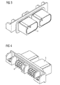
- FIG. 3 shows the plastic plug part with a view onto the plug shaft's opening
- FIG. 4 shows the plastic plug part with a view onto the pc-board plug-in contacts
- FIGS. 5 a, b show the fastening between the plastic plug part, circuit support, and housing baseplate in an enlarged sectional representation
- FIG. 6 shows the rivet sleeve in an enlarged, three-dimensional representation
- FIG. 7 shows the housing baseplate in a three-dimensional representation.
- FIGS. 1 and 2 show in each case as an exemplary embodiment of the invention a perspective view of a control device for a motor vehicle.
- a circuit support 2 Fastened onto a flat housing baseplate 1 is a circuit support 2 that can be seen through the transparently shown housing cover.
- Fastened onto the circuit support 2 is a plastic plug part 3 that is shown in FIG. 3 with a view onto the plug shaft.
- FIG. 4 shows the plastic plug part 3 with a view onto the pc-board plug-in contacts 4 .
- the pc-board plug-in contacts 4 establish the electric connection to printed conductors 14 on the circuit support 2 .
- FIGS. 5 a and 5 b show in a sectional drawing by way of example the fastening between the plastic plug part 3 , circuit support 2 , and housing baseplate 1 .
- Hollow cylindrical, thin-walled rivet pegs 8 have been formed on the housing baseplate 1 through extrusion. Said rivet pegs 8 form—as explained in more detail below—a mechanical connection between the plastic housing part 3 , circuit support 2 , and housing baseplate 1 or, as the case may be, between the circuit support 2 and housing baseplate 1 .
- Each rivet peg 8 has for fastening the plastic plug part 3 been passed through a corresponding recess 12 in the circuit support 2 or, as the case may be, a recess 13 in the plastic plug part 3 .
- the circuit support 2 is also fastened onto the baseplate 1 by means of rivet pegs 8 (only one rivet peg 8 has been drawn in FIGS. 5 a and 5 b ).
- a clump-shaped thickening is in the assembled condition formed at each end of a rivet peg 8 .
- Said thickening forms a closing head 9 of a rivet joint.
- the closing head 9 is formed in a single operation for all rivet pegs 8 when the control device is being produced.
- a hollow cylindrical supporting part 5 is inventively provided to prevent the plastic plug part 3 from being damaged while the closing head 9 is being produced. Said supporting part 5 ( FIG.
- the screw 6 consists of a rivet sleeve 5 produced from high-strength sheet steel through deep-drawing.
- the wall is 0.5 mm thick.
- the rivet sleeve 5 is held in a frictionally engaged manner in the recess 13 embodied as a bore hole. Said sleeve is hence unlosably joined to the plug part 3 , meaning it is an integral constituent of the plastic plug part 3 .
- the plastic plug part 3 is produced through injection molding.
- the rivet sleeve 5 can, though, also be at least partially extrusion coated with the polymeric material of the plug part 3 .
- the rivet sleeve 5 will in that case be inserted into the injection-molding tool as an insert when the plastic plug part 3 is being produced.
- the rivet sleeve 5 is pot-shaped in cross-section with a hole in its base. It has a flange 6 oriented radially outward and a flange 7 oriented radially inward ( FIG. 6 ). The flange 6 oriented radially outward is supported on a shoulder 11 formed in a cavity 10 of the plastic plug part 3 . The closing head 9 is supported on the flange 7 oriented radially inward.
- Said rivet sleeve 5 acts as a rigid intermediate press-on part while the rivet joint is being produced. It insures that neither the deforming forces being applied nor the bearing pressure occurring while the closing head 9 is being formed can damage the plastic plug part 3 during the rivet joint's production. If vibrations are transmitted from the connecting cable to the plastic plug part while the motor vehicle is operating, then said mechanical connection will insure that the electric connection between the pc-board plug-in contacts 4 of the plug part 3 and the printed conductors 12 on the side 15 of the pc board 2 will not be adversely affected.
- FIG. 7 is a perspective view of the housing baseplate 1 for the exemplary embodiment shown.
- Rivet pegs 8 standing out like a tenon can be seen on a side of the housing baseplate 1 adjacent in the assembled condition to the circuit support 2 .
- Said rivet pegs 8 are located in the region of corrugation-like protuberances 16 .
- Said protuberances 16 serve to stiffen the housing baseplate 1 .
- the plastic plug part 3 shown separately in FIG. 3 and FIG. 4 is fastened by means of two opposite rivet pegs identified in FIG. 7 by the reference numeral 8 ′.
- the housing baseplate 1 is made from an aluminum alloy.
- the rivet pegs 8 are higher than their diameter; the height is preferably about 1.5 to six times the diameter of a rivet peg 8 .
- the rivet pegs have been produced in a single operation by extrusion together with the housing baseplate 1 .
- the procedure while the control device is being produced is now for the circuit support 2 together with the plastic plug part 3 thereon that is held by the plugged-in pc-board plug-in contacts 4 to be placed over said rivet pegs 8 and centered by them.
- a closing head 9 is in a directly ensuing work step formed simultaneously on the extremities of all rivet pegs 8 by means of an automatic tool. That produces a secure mechanical connection between the plastic plug part 3 and plate-shaped circuit support 2 on the one hand and—depending on the number/arrangement of the rivet pegs 8 —simultaneously a rivet joint between the circuit support 2 and housing baseplate 1 .
- the plastic plug part 3 can thanks to the rivet sleeve 5 be riveted without sustaining damage.
- the rivet sleeve 5 enables the closing head 9 to be close to the housing baseplate 1 .
- the height of the rivet pegs 8 can be kept low thereby, which is favorable for cold extrusion.
- the electric connection between the contacts 4 of the plastic plug part 3 and the printed conductors 14 on the circuit support 2 will be less fault-prone because the plastic plug part will not be damaged while the rivet joint is being formed.
- the reliability of the electric device can as a result be maintained at a high level over a long period of use even if high acceleration forces act upon the electric device or, as the case may be, strong vibrations are transmitted to the plug 3 via the cable.
Landscapes
- Engineering & Computer Science (AREA)
- Microelectronics & Electronic Packaging (AREA)
- Coupling Device And Connection With Printed Circuit (AREA)
- Connection Of Plates (AREA)
- Details Of Connecting Devices For Male And Female Coupling (AREA)
- Cookers (AREA)
- Motor Or Generator Frames (AREA)
Applications Claiming Priority (3)
| Application Number | Priority Date | Filing Date | Title |
|---|---|---|---|
| AT0035506A AT502834B1 (de) | 2006-03-02 | 2006-03-02 | Elektrisches gerät mit einem auf einem schaltungsträger angeordneten kunststoffsteckerteil |
| AT355/2006 | 2006-03-02 | ||
| PCT/EP2007/050207 WO2007098972A1 (de) | 2006-03-02 | 2007-01-10 | Elektrisches gerät mit einem auf einem schaltungsträger angeordneten kunststoffsteckerteil |
Publications (2)
| Publication Number | Publication Date |
|---|---|
| US20090180265A1 US20090180265A1 (en) | 2009-07-16 |
| US8023273B2 true US8023273B2 (en) | 2011-09-20 |
Family
ID=38117145
Family Applications (1)
| Application Number | Title | Priority Date | Filing Date |
|---|---|---|---|
| US12/224,634 Expired - Fee Related US8023273B2 (en) | 2006-03-02 | 2007-01-10 | Electric device having a plastic plug part arranged on a circuit support |
Country Status (7)
| Country | Link |
|---|---|
| US (1) | US8023273B2 (pl) |
| EP (1) | EP1989934B1 (pl) |
| AT (2) | AT502834B1 (pl) |
| DE (1) | DE502007006101D1 (pl) |
| ES (1) | ES2357978T3 (pl) |
| PL (1) | PL1989934T3 (pl) |
| WO (1) | WO2007098972A1 (pl) |
Cited By (9)
| Publication number | Priority date | Publication date | Assignee | Title |
|---|---|---|---|---|
| US20100255732A1 (en) * | 2007-11-29 | 2010-10-07 | Yoshihiko Kohmura | Metal-resin compound member |
| US20130034975A1 (en) * | 2011-08-01 | 2013-02-07 | Kabushiki Kaisha Toyota Jidoshokki | Connector and structure for connecting circuit board and external connector |
| US20140227908A1 (en) * | 2013-02-08 | 2014-08-14 | Hitachi Metals, Ltd. | Connector supporting structure and connector-equipped electronic device |
| US20140285985A1 (en) * | 2013-03-22 | 2014-09-25 | Mitsubish Electric Corporation | Electronic control device and method of manufacturing electronic control device |
| US20150111435A1 (en) * | 2012-11-09 | 2015-04-23 | Nsk Ltd. | Connector |
| US20150214676A1 (en) * | 2014-01-24 | 2015-07-30 | Eberspächer Climate Control Systems GmbH & Co. KG | Control device for a vehicle heater |
| US9293870B1 (en) * | 2015-03-10 | 2016-03-22 | Continental Automotive Systems, Inc. | Electronic control module having a cover allowing for inspection of right angle press-fit pins |
| US20180177067A1 (en) * | 2016-12-21 | 2018-06-21 | Robert Bosch Llc | Printed Circuit Board Housing including Guiding Ribs |
| US20190204518A1 (en) * | 2017-12-28 | 2019-07-04 | Kui-Hsien Huang | Fiber transmission device |
Families Citing this family (14)
| Publication number | Priority date | Publication date | Assignee | Title |
|---|---|---|---|---|
| DE102009045565A1 (de) * | 2009-10-12 | 2011-04-14 | Robert Bosch Gmbh | Adapterplatte zur Befestigung eines Gehäuses in einem Fahrzeug und korrespondierendes Steuergerät |
| DE102012202342B4 (de) * | 2012-02-16 | 2017-10-12 | Osram Gmbh | Leuchtvorrichtung mit Leiterplatte und Strukturbauteil |
| WO2014095171A1 (de) * | 2012-12-17 | 2014-06-26 | Continental Automotive Gmbh | Gehäuse eines elektronischen steuergeräts |
| DE102013208984B4 (de) * | 2013-05-15 | 2022-06-30 | Zf Friedrichshafen Ag | Steuergerät |
| KR101575265B1 (ko) * | 2014-09-30 | 2015-12-07 | 현대오트론 주식회사 | 고정 부재를 이용한 차량의 전자 제어 장치 및 그 제조 방법 |
| JP2017098332A (ja) * | 2015-11-19 | 2017-06-01 | 株式会社ジェイテクト | 電子回路装置 |
| JP6096336B1 (ja) | 2016-01-18 | 2017-03-15 | タイコエレクトロニクスジャパン合同会社 | コネクタハウジング |
| FR3048155B1 (fr) * | 2016-02-19 | 2018-03-23 | Continental Automotive France | Plaque de base pour boitier de protection de circuit imprime munie d'une ebauche de rivet portee par un filtre d'aeration |
| DE102016110052B4 (de) * | 2016-05-31 | 2018-10-04 | Endress+Hauser SE+Co. KG | Feldgerät mit einer gekapselten Leiterplatte sowie Verfahren zur Kapselung einer Leiterplatte eines solchen Feldgerätes |
| DE102016216177A1 (de) | 2016-08-29 | 2018-03-01 | Robert Bosch Gmbh | Steckerleiste für ein Steuergerät |
| KR102030824B1 (ko) * | 2017-11-01 | 2019-10-10 | 현대오트론 주식회사 | 전자 제어 장치 |
| JP7044736B2 (ja) * | 2019-06-10 | 2022-03-30 | 矢崎総業株式会社 | 電子部品ユニット |
| US11233363B2 (en) * | 2019-09-23 | 2022-01-25 | Ford Global Technologies, Llc | Aluminum alloy header plate with ceramic coating for battery assembly |
| IT202000025363A1 (it) * | 2020-10-27 | 2022-04-27 | Marelli Europe Spa | Modulo elettronico sigillato munito di mezzi di fissaggio perfezionati, e relativo metodo di assemblaggio |
Citations (9)
| Publication number | Priority date | Publication date | Assignee | Title |
|---|---|---|---|---|
| EP0250097A1 (en) | 1986-06-19 | 1987-12-23 | The Whitaker Corporation | Electrical connector for easy assembly onto a circuit board and eyelets therefor |
| US5231561A (en) | 1992-02-18 | 1993-07-27 | Motorola, Inc. | Mounting method and apparatus for PWA shielding |
| US6034876A (en) * | 1996-06-27 | 2000-03-07 | Japan Aviation Electronics Industry, Limited | Electronic device comprising structure fixing electrical connector directly to device case through no printed circuit board having the electrical connector |
| US6042392A (en) * | 1996-10-28 | 2000-03-28 | Yazaki Corporation | Printed circuit board connector fitting structure |
| US6628523B2 (en) * | 2001-02-08 | 2003-09-30 | Denso Corporation | Casing for electronic control unit |
| US6707678B2 (en) * | 1999-09-17 | 2004-03-16 | Denso Corporation | Casing for electronic control devices |
| US6717051B2 (en) * | 2001-02-21 | 2004-04-06 | Denso Corporation | Electronic control unit for use in automotive vehicle |
| JP2004303504A (ja) | 2003-03-31 | 2004-10-28 | Yazaki Corp | コネクタ付き電子ユニット及びその製造方法 |
| US7616448B2 (en) * | 2007-09-14 | 2009-11-10 | Delphi Technologies, Inc. | Wrap-around overmold for electronic assembly |
Family Cites Families (1)
| Publication number | Priority date | Publication date | Assignee | Title |
|---|---|---|---|---|
| DE20113884U1 (de) * | 2001-08-22 | 2003-01-02 | ITT Manufacturing Enterprises, Inc., Wilmington, Del. | Elektrischer Verbinder für eine Leiterplatte |
-
2006
- 2006-03-02 AT AT0035506A patent/AT502834B1/de not_active IP Right Cessation
-
2007
- 2007-01-10 ES ES07703754T patent/ES2357978T3/es active Active
- 2007-01-10 DE DE502007006101T patent/DE502007006101D1/de active Active
- 2007-01-10 WO PCT/EP2007/050207 patent/WO2007098972A1/de not_active Ceased
- 2007-01-10 US US12/224,634 patent/US8023273B2/en not_active Expired - Fee Related
- 2007-01-10 EP EP07703754A patent/EP1989934B1/de not_active Not-in-force
- 2007-01-10 PL PL07703754T patent/PL1989934T3/pl unknown
- 2007-01-10 AT AT07703754T patent/ATE493872T1/de active
Patent Citations (10)
| Publication number | Priority date | Publication date | Assignee | Title |
|---|---|---|---|---|
| EP0250097A1 (en) | 1986-06-19 | 1987-12-23 | The Whitaker Corporation | Electrical connector for easy assembly onto a circuit board and eyelets therefor |
| US5231561A (en) | 1992-02-18 | 1993-07-27 | Motorola, Inc. | Mounting method and apparatus for PWA shielding |
| US6034876A (en) * | 1996-06-27 | 2000-03-07 | Japan Aviation Electronics Industry, Limited | Electronic device comprising structure fixing electrical connector directly to device case through no printed circuit board having the electrical connector |
| US6042392A (en) * | 1996-10-28 | 2000-03-28 | Yazaki Corporation | Printed circuit board connector fitting structure |
| US6707678B2 (en) * | 1999-09-17 | 2004-03-16 | Denso Corporation | Casing for electronic control devices |
| US6628523B2 (en) * | 2001-02-08 | 2003-09-30 | Denso Corporation | Casing for electronic control unit |
| US6717051B2 (en) * | 2001-02-21 | 2004-04-06 | Denso Corporation | Electronic control unit for use in automotive vehicle |
| US6927337B2 (en) * | 2001-02-21 | 2005-08-09 | Denso Corporation | Electronic control unit for use in automotive vehicle |
| JP2004303504A (ja) | 2003-03-31 | 2004-10-28 | Yazaki Corp | コネクタ付き電子ユニット及びその製造方法 |
| US7616448B2 (en) * | 2007-09-14 | 2009-11-10 | Delphi Technologies, Inc. | Wrap-around overmold for electronic assembly |
Cited By (16)
| Publication number | Priority date | Publication date | Assignee | Title |
|---|---|---|---|---|
| US8357015B2 (en) * | 2007-11-29 | 2013-01-22 | Ngk Spark Plug Co., Ltd. | Metal-resin compound member |
| US20100255732A1 (en) * | 2007-11-29 | 2010-10-07 | Yoshihiko Kohmura | Metal-resin compound member |
| US8814576B2 (en) * | 2011-08-01 | 2014-08-26 | Kabushiki Kaisha Toyota Jidoshokki | Connector and structure for connecting circuit board and external connector |
| US20130034975A1 (en) * | 2011-08-01 | 2013-02-07 | Kabushiki Kaisha Toyota Jidoshokki | Connector and structure for connecting circuit board and external connector |
| US9099800B2 (en) * | 2012-11-09 | 2015-08-04 | Nsk Ltd. | Connector |
| US20150111435A1 (en) * | 2012-11-09 | 2015-04-23 | Nsk Ltd. | Connector |
| US20140227908A1 (en) * | 2013-02-08 | 2014-08-14 | Hitachi Metals, Ltd. | Connector supporting structure and connector-equipped electronic device |
| US9197002B2 (en) * | 2013-02-08 | 2015-11-24 | Hitachi Metals, Ltd. | Connector supporting structure and connector-equipped electronic device |
| US20140285985A1 (en) * | 2013-03-22 | 2014-09-25 | Mitsubish Electric Corporation | Electronic control device and method of manufacturing electronic control device |
| US10010006B2 (en) * | 2013-03-22 | 2018-06-26 | Mitsubishi Electric Corporation | Electronic control device and method of manufacturing electronic control device |
| US20150214676A1 (en) * | 2014-01-24 | 2015-07-30 | Eberspächer Climate Control Systems GmbH & Co. KG | Control device for a vehicle heater |
| US9472906B2 (en) * | 2014-01-24 | 2016-10-18 | Eberspächer Climate Control Systems GmbH & Co. KG | Control device for a vehicle heater |
| US9293870B1 (en) * | 2015-03-10 | 2016-03-22 | Continental Automotive Systems, Inc. | Electronic control module having a cover allowing for inspection of right angle press-fit pins |
| US20180177067A1 (en) * | 2016-12-21 | 2018-06-21 | Robert Bosch Llc | Printed Circuit Board Housing including Guiding Ribs |
| US10251297B2 (en) * | 2016-12-21 | 2019-04-02 | Robert Bosch Llc | Printed circuit board housing including guiding ribs |
| US20190204518A1 (en) * | 2017-12-28 | 2019-07-04 | Kui-Hsien Huang | Fiber transmission device |
Also Published As
| Publication number | Publication date |
|---|---|
| WO2007098972A1 (de) | 2007-09-07 |
| DE502007006101D1 (de) | 2011-02-10 |
| US20090180265A1 (en) | 2009-07-16 |
| EP1989934B1 (de) | 2010-12-29 |
| ATE493872T1 (de) | 2011-01-15 |
| AT502834B1 (de) | 2007-06-15 |
| ES2357978T3 (es) | 2011-05-04 |
| AT502834A4 (de) | 2007-06-15 |
| EP1989934A1 (de) | 2008-11-12 |
| PL1989934T3 (pl) | 2011-05-31 |
Similar Documents
| Publication | Publication Date | Title |
|---|---|---|
| US8023273B2 (en) | Electric device having a plastic plug part arranged on a circuit support | |
| US8337251B2 (en) | Tolerance-compensating current distribution board | |
| JP5261645B2 (ja) | 自動車用制御装置 | |
| CN101469734A (zh) | 用于将铆螺母结合到塑料部件内的系统 | |
| JP2023510118A (ja) | バッテリシェル、トラクションバッテリ、および自動車 | |
| US8916079B2 (en) | Method for producing an electronic component | |
| US7506633B2 (en) | Press-fit of sensor assembly in electronic throttle control application | |
| JPH1117204A (ja) | 太陽電池モジュール用端子箱及び太陽電池モジュール | |
| EP2000364A8 (en) | A dashboard assembly for a motor vehicle provided with a connector for connecting a portable electronic device | |
| EP2774820B1 (en) | Housing for a windscreen wiper motor, method for producing a housing for a windscreen wiper motor, and windscreen wiper motor | |
| KR101750116B1 (ko) | 후크 터미널 | |
| CN101855784A (zh) | 用于俘获容置螺钉在连接器端子中的装置及方法 | |
| CN107110193A (zh) | 用于将扭矩导入塑料外壳的金属固定件 | |
| JP2009505883A (ja) | 乗物の壁に物体を取り付けるための装置および方法 | |
| US20210352815A1 (en) | Housing Assembly and Housing Assembly Method | |
| US20130063903A1 (en) | Arrangement comprising an electric and/or electronic module and a circuit carrier | |
| US10851823B2 (en) | Device for fastening to a fastening projection of a carrier component | |
| KR20130049156A (ko) | 캐리어 플레이트에 트랜스미션 제어 모듈용 제어 장치의 고정 | |
| CN215596149U (zh) | 一种传感器螺栓预安装防脱落结构 | |
| CN111299453B (zh) | 车辆备件的制造方法 | |
| US6683257B1 (en) | Attachment clip | |
| US9151319B2 (en) | Mounting structure | |
| CN207009789U (zh) | 线材接头结构 | |
| US20080156961A1 (en) | Vibration isolation mount for a motor assembly | |
| KR200409576Y1 (ko) | 와이어 하네스 조립용 지그 |
Legal Events
| Date | Code | Title | Description |
|---|---|---|---|
| AS | Assignment |
Owner name: SIEMENS AG OSTERREICH, AUSTRIA Free format text: ASSIGNMENT OF ASSIGNORS INTEREST;ASSIGNORS:CHLUMSKY, LUBOMIR;HELLINGER, LEOPOLD;KOCEVAR, ANTON;AND OTHERS;REEL/FRAME:021507/0405;SIGNING DATES FROM 20080626 TO 20080821 Owner name: SIEMENS AG OSTERREICH, AUSTRIA Free format text: ASSIGNMENT OF ASSIGNORS INTEREST;ASSIGNORS:CHLUMSKY, LUBOMIR;HELLINGER, LEOPOLD;KOCEVAR, ANTON;AND OTHERS;SIGNING DATES FROM 20080626 TO 20080821;REEL/FRAME:021507/0405 |
|
| AS | Assignment |
Owner name: MELECS EWS GMBH & CO KG,AUSTRIA Free format text: ASSIGNMENT OF ASSIGNORS INTEREST;ASSIGNOR:SIEMENS AG OSTERREICH;REEL/FRAME:024291/0981 Effective date: 20100331 Owner name: MELECS EWS GMBH & CO KG, AUSTRIA Free format text: ASSIGNMENT OF ASSIGNORS INTEREST;ASSIGNOR:SIEMENS AG OSTERREICH;REEL/FRAME:024291/0981 Effective date: 20100331 |
|
| REMI | Maintenance fee reminder mailed | ||
| LAPS | Lapse for failure to pay maintenance fees | ||
| STCH | Information on status: patent discontinuation |
Free format text: PATENT EXPIRED DUE TO NONPAYMENT OF MAINTENANCE FEES UNDER 37 CFR 1.362 |
|
| FP | Lapsed due to failure to pay maintenance fee |
Effective date: 20150920 |