US8002539B2 - Injection stretch blow molding system with rotating and linear conveying functions - Google Patents
Injection stretch blow molding system with rotating and linear conveying functions Download PDFInfo
- Publication number
- US8002539B2 US8002539B2 US12/468,173 US46817309A US8002539B2 US 8002539 B2 US8002539 B2 US 8002539B2 US 46817309 A US46817309 A US 46817309A US 8002539 B2 US8002539 B2 US 8002539B2
- Authority
- US
- United States
- Prior art keywords
- bottleneck
- seat
- mold
- rotating
- operating position
- Prior art date
- Legal status (The legal status is an assumption and is not a legal conclusion. Google has not performed a legal analysis and makes no representation as to the accuracy of the status listed.)
- Expired - Fee Related, expires
Links
Images


Classifications
-
- B—PERFORMING OPERATIONS; TRANSPORTING
- B29—WORKING OF PLASTICS; WORKING OF SUBSTANCES IN A PLASTIC STATE IN GENERAL
- B29C—SHAPING OR JOINING OF PLASTICS; SHAPING OF MATERIAL IN A PLASTIC STATE, NOT OTHERWISE PROVIDED FOR; AFTER-TREATMENT OF THE SHAPED PRODUCTS, e.g. REPAIRING
- B29C49/00—Blow-moulding, i.e. blowing a preform or parison to a desired shape within a mould; Apparatus therefor
- B29C49/28—Blow-moulding apparatus
- B29C49/30—Blow-moulding apparatus having movable moulds or mould parts
- B29C49/32—Blow-moulding apparatus having movable moulds or mould parts moving "to and fro"
-
- B—PERFORMING OPERATIONS; TRANSPORTING
- B29—WORKING OF PLASTICS; WORKING OF SUBSTANCES IN A PLASTIC STATE IN GENERAL
- B29C—SHAPING OR JOINING OF PLASTICS; SHAPING OF MATERIAL IN A PLASTIC STATE, NOT OTHERWISE PROVIDED FOR; AFTER-TREATMENT OF THE SHAPED PRODUCTS, e.g. REPAIRING
- B29C49/00—Blow-moulding, i.e. blowing a preform or parison to a desired shape within a mould; Apparatus therefor
- B29C49/02—Combined blow-moulding and manufacture of the preform or the parison
- B29C49/06—Injection blow-moulding
- B29C49/061—Injection blow-moulding with parison holding means displaceable between injection and blow stations
-
- B—PERFORMING OPERATIONS; TRANSPORTING
- B29—WORKING OF PLASTICS; WORKING OF SUBSTANCES IN A PLASTIC STATE IN GENERAL
- B29D—PRODUCING PARTICULAR ARTICLES FROM PLASTICS OR FROM SUBSTANCES IN A PLASTIC STATE
- B29D22/00—Producing hollow articles
- B29D22/003—Containers for packaging, storing or transporting, e.g. bottles, jars, cans, barrels, tanks
-
- B—PERFORMING OPERATIONS; TRANSPORTING
- B29—WORKING OF PLASTICS; WORKING OF SUBSTANCES IN A PLASTIC STATE IN GENERAL
- B29C—SHAPING OR JOINING OF PLASTICS; SHAPING OF MATERIAL IN A PLASTIC STATE, NOT OTHERWISE PROVIDED FOR; AFTER-TREATMENT OF THE SHAPED PRODUCTS, e.g. REPAIRING
- B29C49/00—Blow-moulding, i.e. blowing a preform or parison to a desired shape within a mould; Apparatus therefor
- B29C49/02—Combined blow-moulding and manufacture of the preform or the parison
- B29C2049/023—Combined blow-moulding and manufacture of the preform or the parison using inherent heat of the preform, i.e. 1 step blow moulding
-
- B—PERFORMING OPERATIONS; TRANSPORTING
- B29—WORKING OF PLASTICS; WORKING OF SUBSTANCES IN A PLASTIC STATE IN GENERAL
- B29L—INDEXING SCHEME ASSOCIATED WITH SUBCLASS B29C, RELATING TO PARTICULAR ARTICLES
- B29L2031/00—Other particular articles
- B29L2031/712—Containers; Packaging elements or accessories, Packages
- B29L2031/7158—Bottles
Definitions
- the present invention relates to an injection stretch blow molding system, more particularly to an injection stretch blow molding system with rotating and linear conveying functions.
- An injection stretch blow molding art is commonly used for a hollow semi-sealed container and is processed through an injection stretch blow molding apparatus, nowadays containers for beverages, perfumes or medicines are often made by an injection stretch blow molding apparatus.
- injection stretch blow molding is that a polymer material is adopted and is formed as a hollow preform with a means of injection molding through a preform mold of an injecting mechanism, then the preform is placed in a bottle blowing mold of an extending and blowing mechanism, then an bottle inflating means is processed so the heated and softened preform is expanded till right next to the inner wall of the bottle blowing mold, then the shaped bottle member is released through a pushing mechanism. So in an injection stretch blow molding operation, the thread section of the bottleneck is often served as a section to be clamped.
- a transversal (horizontal) blow molding apparatus with two operating positions of injecting and extending and blowing has been developed by skilled people in the art
- a mobile mold sheet and a rotary mold sheet are installed in parallel with a right/left arraying means
- the left end of the rotary mold sheet is connected to an axial core of a rotation seat of a supporting rack
- the mobile mold sheet is provided with a core mold and an extending rod
- the rotary mold sheet is provided with two identical bottleneck seat sets
- a retaining mold sheet is provided with an injection mold and a bottle blowing mold
- the core mold and the injection mold are correspondingly arrayed with respect to one of the two bottleneck seat sets, so a preform is able to be injected and formed
- the extending rod and the bottle blowing mold are correspondingly arrayed with respect to the other bottleneck seat set so the preform is able to be extended and blown to form a bottle member
- the rotary mold sheet is up/down 180-degree rotated through the rotation seat so
- the size of the bottle blowing mold is limited because of the size of the rotary mold sheet (rotating plate); so only a bottle member with small size can be made by the bottle blowing mold.
- operations of opening and engaging the bottle blowing mold are performed through a gas cylinder because the space around the bottle blowing mold is limited, so a mold locking capacity may not be larger enough and an unqualified bottle member may be produced.
- the applicant of the present invention has devoted himself to design and commercially distribute injection stretch blow molding apparatuses, with a hope to overcome disadvantages that the described blow molding apparatus with two or more operating positions can only produce small sized bottle members due to the limitation of the size of the rotating plate; an art has been designed by the applicant which is that after an injected preform is rotated from a first operating position to a second operating position through the lifting and rotating mechanism, the preform is then conveyed to an extending and blowing mechanism located at a third operating position through a linear convey means provided by a conveying mechanism, so that the extending and blowing mechanism is provided with a variety of modifications, after try and error the present invention “Injection Stretch Blow Molding System with Rotating and Linear Conveying Functions” is provided.
- One object of the present invention is to provide an injection stretch blow molding system with rotating and linear conveying functions, in which an extending and blowing mechanism is provided at a lateral end of a lifting and rotating mechanism in a radial direction, so after a preform is rotated from a first operating position to a second operating position by the lifting and rotating mechanism, the preform is then conveyed to an extending and blowing mechanism located at a third position through a linear convey means provided by a conveying mechanism, an operation of extending and blowing is therefore able to be proceeded.
- Another object of the present invention is to provide an injection stretch blow molding system with rotating and linear conveying functions with a space design of an injecting mechanism and an extending and blowing mechanism, the size of the injection stretch blow molding system is able to be reduced and space around the extending and blowing mechanism is enlarged, so an engaging driving device with a better mold locking capacity is able to be adopted for opening or engaging molds, e.g. a hydraulic cylinder, a bottle member having a larger size is able to be extended and blown, thus the extending and blowing mechanism is provided with a variety of modifications.
- one solution provided by the present invention is to provide an injection stretch blow molding system with rotating and linear conveying functions, comprises: a lifting and rotating mechanism, having a lifting seat that is able to ascend/descend on a machine body, a rotating plate is pivotally provided in the lifting seat, two bottleneck seats are oppositely and radially provided on the bottom surface of the rotating plate, each of the bottleneck seats has at least one bottleneck mold, with the rotation of the rotating plate, positions of the two bottleneck seats are able to be interchanged between a first and a second operating positions; an injecting mechanism installed at the first operating position, the injecting mechanism has a female mold installed below the rotating plate and at least one core mold installed on the lifting seat and able to be longitudinally moved, the core mold is able to pass through the rotating plate and the bottleneck mold of the bottleneck seat and enter the female mold, so a preform injecting operation is able to be proceeded; a conveying mechanism installed at the second operating position, the conveying mechanism has a conveying seat
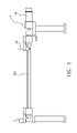
- FIG. 1 is a front view of the injection stretch blow molding system with rotating and linear conveying functions provided by the present invention
- FIG. 2 is a top view of the injection stretch blow molding system of the present invention
- FIG. 3 is a right side view of the injection stretch blow molding system of the present invention.
- FIG. 4 is a left side view of the injection stretch blow molding system of the present invention.
- FIG. 5 is a schematic view of the conveying mechanism of the present invention.
- FIG. 6 is a schematic view of the lifting and rotating mechanism and the extending and blowing mechanism of the present invention.
- FIG. 7 to FIG. 10 are flowcharts of operations of conveying, extending and blowing, and pushing of the injection stretch blow molding system of the present invention
- FIG. 11 and FIG. 12 are schematic views of the lifting and rotating mechanism and the conveying mechanism of another embodiment of the present invention.
- FIG. 13 and FIG. 14 are a right side view and a left side view of the lifting and rotating mechanism and the conveying mechanism of another embodiment of the present invention.
- the injection stretch blow molding system with rotating and linear conveying functions provided by the present invention is composed by a lifting and rotating mechanism 1 , an injecting mechanism 2 , a conveying mechanism 3 , an extending and blowing mechanism 4 and a pushing mechanism 5 .
- a rotating plate 12 is pivotally installed in a lifting seat 11 , the lifting seat 11 is driven by a lifting driving device 13 , e.g. a hydraulic cylinder or a gas cylinder, and the listing seat 11 is installed on plural supporting racks 14 provided in a machine body and is able to be longitudinally moved thereon, and the rotating plate 12 is synchronously driven to longitudinally moved.
- a transmission device 15 e.g.
- a servo motor is installed on a top end of the rotating plate 12 so positions of a first and a second bottleneck seats 121 , 122 oppositely and radially provided on a bottom surface of the rotating plate 12 are able to be interchanged with an angle of 180 degree, in other words a first operating position and a second operating position are interchanged.
- the first and the second bottleneck seats 121 , 122 are provided with one or more bottleneck molds 123 , and the first and the second bottleneck seats 121 , 122 are respectively defined as a half of a mold, in other words the first and the second bottleneck seats 121 , 122 are respectively composed by a half mold, and a resilient device, e.g.
- a tightening spring is served to tighten the two half molds when the two half molds are engaged, two ends of each of the first and the second bottleneck seats 121 , 122 respectively have an inwardly-beveled surface, so an inwardly-beveled concave section is defined when the first and the second bottleneck seats 121 , 122 are engaged.
- each of the two bottleneck seats 121 , 122 are respectively provided in a pair of retaining sliding rails 16 .
- a latching device 17 is therefore provided at an outer end of one of each pair of retaining sliding rails 16 , a buckling tenon 171 provided one end of the latching device 17 passes through the retaining sliding rail 16 and is buckled in a buckling slot 124 preset on the bottleneck seat 121 or 122 , so each of the bottleneck seats 121 , 122 are individually positioned and retained.
- the injecting mechanism 2 is composed by a female mold 21 and a core mold 22 , the female mold 21 is fastened on the machine body and is disposed below the rotating plate 12 of the lifting and rotating mechanism 1 , and the core mold 22 is provided on top of the lifting seat 11 , so that after the core mold 22 passes through the rotating plate 12 downwardly driven by the lifting seat 11 and passes through a bottleneck mold 123 provided on the first bottleneck seat 121 or the second bottleneck seat 122 , the core mold 22 enters the female mold 21 for forming a mold engaging status.
- a melted plastic material is injected into the female mold 21 through an injecting pipe 24 of an injecting machine so as to obtain a preform; after an operation of mold opening is processed, in other words the core mold 22 and the rotating plate 12 of the lifting seat 11 are lifted and the preform is released from the female mold 21 and is clamped by the bottleneck mold 123 of the first bottleneck seat 121 (as shown in FIG. 3 ), thus the preform is at the first operating position where the injecting mechanism 2 is provided.
- a hydraulic cylinder protrudes and pushes a resilient section 172 provided on the other end of the latching device 17 so the buckling tenon 171 is inwardly retracted and the first bottleneck seat 121 is released from a latching status, so the first bottleneck seat 121 and the preform clamped by the bottleneck mold 123 thereof are able to be conveyed to a third operating position through the conveying mechanism 3 , as shown in FIG. 8 , the position is where the extending and blowing mechanism 4 is placed.
- the first bottleneck seat 121 provided below the rotating plate 12 is rotated from the first operating position to the second operating position, and the second bottleneck seat 122 is rotated from the second operating position to the first operating position, the two bottleneck seats 121 , 122 are descended with the decent movement of the rotating plate 12 so the second bottleneck seat 122 is disposed on top of the female mold 21 , meanwhile the core mold 22 is descended and provided in the female mold 21 so as to form a mold engaging status, an injecting operation of preform is therefore able to be processed.
- a connection is formed between a connecting pin 32 protrudingly provided on a conveying seat 31 and a pin hole 125 provided at an end section of the first bottleneck seat 121 ; and through operations of a convey driving device 33 , e.g. a servo motor, the conveying seat 31 pivotally connected to plural screw rods 331 is driven to move towards the extending and blowing mechanism 4 located at the third operating position.
- a convey driving device 33 e.g. a servo motor
- a pair of extending sliding rails 34 are installed on top of a bottle blowing mold 41 of the extending and blowing mechanism 4 , the pair of extending sliding rails 34 is provided adjacent to one of the pairs of retaining sliding rails 16 of the rotating plate 12 , so with transversal movements of the conveying seat 31 and the connecting pin 32 , the first bottleneck seat 121 is able to be moved to the extending and blowing mechanism 4 located at the third operating position along the pair of extending sliding rails 34 .
- Reciprocal-type members of the conveying mechanism 3 are not limited to the described convey driving device 33 and the screw rods 331 , the reciprocal-type members can also be conventional retracting driving devices, e.g. gas cylinders or hydraulic cylinders, so that a linear conveying function is obtained.
- the extending and blowing mechanism 4 is composed by the bottle blowing mold 41 and the extending rod 42 extending from the top end of the bottle blowing mold 41 ; after the first bottleneck seat 121 and the preform clamped by the bottleneck mold 123 thereof that are conveyed by the conveying mechanism 3 enter the bottle blowing mold 41 which is in an open status, engaging driving devices 43 , e.g. hydraulic cylinders, provided at two ends are processed with an engaging operation, meanwhile the extending rod 42 is descended with an operation of a retracting driving device 44 , e.g.
- engaging driving devices 43 e.g. hydraulic cylinders
- the extending rod 42 is retracted and the bottle blowing mold 41 is opened by the engaging driving devices 43 , the first bottleneck seat 121 and the bottle member clamped by the bottleneck mold 123 are conveyed to the second operating position through the conveying mechanism 3 , so the buckling tenon 171 of the latching device 17 is automatically buckled in the buckling slot 124 of the first bottleneck seat 121 , a positioning status is therefore obtained.
- the pushing mechanism 5 has a bottle releasing device 51 which is a pushing blades 511 having a beveled-craft thickness and being formed as in a flat sharp shape, e.g. screw knifes, and are provided at two ends of a connecting rod 512 driven by a retracting driving device 52 for performing an ascent/descent movement.
- a bottle releasing device 51 which is a pushing blades 511 having a beveled-craft thickness and being formed as in a flat sharp shape, e.g. screw knifes, and are provided at two ends of a connecting rod 512 driven by a retracting driving device 52 for performing an ascent/descent movement.
- the pair of pushing blades 511 reach the concave surfaces formed on the two beveled surfaces provided at the two lateral ends of the first bottleneck seat 121 and the bottleneck mold 23 is outwardly expanded, a pushing rod 53 provided on the connecting rod 512 enters the bottleneck mold 123 of the first bottleneck seat 121 , so the bottleneck of the bottle member is extruded and the bottle member after being expanded and blown is facilitated to fall, then the pair of pushing blades 511 retract to original positions with the connecting rod 512 , the fallen bottle member is then conveyed by a convey belt 6 to the exterior of the machine body.
- the rotating plate 12 when being conveyed from the second operating position to the third operating position, the rotating plate 12 has to descend with the descent movement of the lifting seat 11 , so that the pin hole 125 of the first or the second bottleneck seat 121 or 122 serving to clamp the preform is able to be connected to the connecting pin 32 of the conveying seat 31 , so the bottleneck seat 121 or 122 can be conveyed; during this procedure, the bottle blowing mold 41 is in an open status and an engaging operation thereof may consume 1 to 2 seconds, such consumed time may be considered as a negative factor for an automated continuous production.
- an extending sheet 111 is integratedly provided to the lifting seat 11 towards the direction of the extending and blowing mechanism 4 located at the third operating position, the top surface thereof is served to install the extending and blowing mechanism 4 , the bottom surface thereof is provided with a pair of extending sliding rails 34 that is adjacent to one of the pairs of retaining sliding rails 16 of the rotating plate 12 , so the first or the second bottleneck seats 121 , 122 can be conveyed by the conveying mechanism 3 installed at the outer end of the second operating position through the lifting seat 11 .
- a connecting pin 32 e.g. an air cylinder, is provided on a conveying seat 31 of the conveying mechanism 3 , when a preform is clamped by either of the bottleneck seats 121 , 122 that is in an ascent status and is rotated from the first operating position to the second operating position, the connecting pin 32 immediately protrudes and inserts into the pin hole 125 of the bottleneck seat so as to form a connection.
- the conveying seat 31 pivotally connected to at least one screw rod 331 is moved towards the extending and blowing mechanism 4 located at the third operating position.
- the lifting seat 11 is descended so the first bottleneck seat 121 is provided on the bottle blowing mold 41 and the preform is directly inserted into the bottle blowing mold 41 which is in an engaging status;
- the second bottleneck seat 122 is provided on the female mold 21 and the core mold 22 passes through the second bottleneck seat 122 and the bottleneck mold 123 and is inserted into the female mold 21 , so operations of extending and blowing and injecting can be respectively processed; so the engaging time of the bottle blowing mold 41 can be reduced and the production capacity is increased.
- the extending and blowing mechanism is provided at a lateral end of the lifting and rotating mechanism in a radial direction, so after the preform is rotated from the first operating position to the second operating position through the lifting and rotating mechanism, the preform is conveyed to the extending and blowing mechanism located at the third operating position through a linear convey of the conveying mechanism; because space around the extending and blowing mechanism is enlarged, engaging driving devices with better mold-locking capacities are able to be adopted, e.g.
Landscapes
- Engineering & Computer Science (AREA)
- Mechanical Engineering (AREA)
- Manufacturing & Machinery (AREA)
- Blow-Moulding Or Thermoforming Of Plastics Or The Like (AREA)
Applications Claiming Priority (3)
| Application Number | Priority Date | Filing Date | Title |
|---|---|---|---|
| TW97209400U | 2008-05-29 | ||
| TW097209400 | 2008-05-29 | ||
| TW097209400U TWM344969U (en) | 2008-05-29 | 2008-05-29 | Bottle-blowing system having rotational and linear transfer |
Publications (2)
| Publication Number | Publication Date |
|---|---|
| US20090297654A1 US20090297654A1 (en) | 2009-12-03 |
| US8002539B2 true US8002539B2 (en) | 2011-08-23 |
Family
ID=41380157
Family Applications (1)
| Application Number | Title | Priority Date | Filing Date |
|---|---|---|---|
| US12/468,173 Expired - Fee Related US8002539B2 (en) | 2008-05-29 | 2009-05-19 | Injection stretch blow molding system with rotating and linear conveying functions |
Country Status (4)
| Country | Link |
|---|---|
| US (1) | US8002539B2 (zh) |
| JP (1) | JP3152733U (zh) |
| KR (1) | KR200462557Y1 (zh) |
| TW (1) | TWM344969U (zh) |
Cited By (1)
| Publication number | Priority date | Publication date | Assignee | Title |
|---|---|---|---|---|
| US11135746B2 (en) | 2017-07-05 | 2021-10-05 | Tsai-Shun Chang | Rapid mold replacing device for use in molding machine |
Families Citing this family (11)
| Publication number | Priority date | Publication date | Assignee | Title |
|---|---|---|---|---|
| TWM344969U (en) | 2008-05-29 | 2008-11-21 | Zai-Shun Zhang | Bottle-blowing system having rotational and linear transfer |
| KR101612410B1 (ko) * | 2015-03-18 | 2016-04-14 | 이제관 | 완성품 변형방지용 보호캡을 구비한 블로우 사출성형기의 완성품 배출장치 |
| JP6602971B2 (ja) * | 2015-06-26 | 2019-11-06 | シンウ コステック カンパニー リミテッド | 容器製造装置 |
| KR101597608B1 (ko) * | 2015-06-26 | 2016-02-26 | 신우코스텍(주) | 용기 제조 장치용 용기 반출 모듈 |
| CN106842354B (zh) * | 2016-12-27 | 2018-12-25 | 东莞市朗信机械有限公司 | 一种封口检测装置及检测方法 |
| CN107953501B (zh) * | 2017-10-17 | 2023-10-20 | 福建鸿龙机械有限公司 | 一种转盘式eva鞋底二次发泡成型机及其成型方法 |
| TWI741859B (zh) * | 2020-10-28 | 2021-10-01 | 張再順 | 用於成型機的快速換模裝置(三) |
| CN113198091B (zh) * | 2021-04-15 | 2022-11-22 | 上海中医药大学附属龙华医院 | 药线制作系统及药线制作方法 |
| CN113650237B (zh) * | 2021-07-07 | 2023-09-08 | 宁波均胜群英汽车系统股份有限公司 | 一种用于生产汽车空调叶片组件的模内装配模具 |
| CN114772264A (zh) * | 2022-04-29 | 2022-07-22 | 永康中奥自动化科技有限公司 | 一种带取放机械手的保温杯加工液压拉伸整形设备 |
| KR102497146B1 (ko) | 2022-08-05 | 2023-02-07 | 주식회사 네오블로 | 사출연신블로우머신의 플라스틱 용기 제조를 위한 턴 테이블 어셈블리 |
Citations (4)
| Publication number | Priority date | Publication date | Assignee | Title |
|---|---|---|---|---|
| US4726756A (en) * | 1984-05-22 | 1988-02-23 | Katashi Aoki | Temperature control blow molding equipment in injection stretch blow molding machine |
| US4744742A (en) * | 1982-12-28 | 1988-05-17 | Katashi Aoki | Molder for molding double-layered preforms in an injection, stretching and blow molding machine |
| US5213822A (en) * | 1989-07-31 | 1993-05-25 | Nissei Asb Machine Co., Ltd. | Injection stretch blow molding apparatus |
| US5516274A (en) * | 1994-09-23 | 1996-05-14 | Electra Form, Inc. | Stretch blow molding machine with movable blow mold assembly |
Family Cites Families (1)
| Publication number | Priority date | Publication date | Assignee | Title |
|---|---|---|---|---|
| TWM344969U (en) | 2008-05-29 | 2008-11-21 | Zai-Shun Zhang | Bottle-blowing system having rotational and linear transfer |
-
2008
- 2008-05-29 TW TW097209400U patent/TWM344969U/zh not_active IP Right Cessation
-
2009
- 2009-05-08 KR KR2020090005602U patent/KR200462557Y1/ko not_active IP Right Cessation
- 2009-05-13 JP JP2009003115U patent/JP3152733U/ja not_active Expired - Lifetime
- 2009-05-19 US US12/468,173 patent/US8002539B2/en not_active Expired - Fee Related
Patent Citations (5)
| Publication number | Priority date | Publication date | Assignee | Title |
|---|---|---|---|---|
| US4744742A (en) * | 1982-12-28 | 1988-05-17 | Katashi Aoki | Molder for molding double-layered preforms in an injection, stretching and blow molding machine |
| US4726756A (en) * | 1984-05-22 | 1988-02-23 | Katashi Aoki | Temperature control blow molding equipment in injection stretch blow molding machine |
| US5213822A (en) * | 1989-07-31 | 1993-05-25 | Nissei Asb Machine Co., Ltd. | Injection stretch blow molding apparatus |
| US5516274A (en) * | 1994-09-23 | 1996-05-14 | Electra Form, Inc. | Stretch blow molding machine with movable blow mold assembly |
| US5516274B1 (en) * | 1994-09-23 | 1997-03-18 | Electra Form Inc | Stretch blow molding machine with movable blow mold assembly |
Cited By (1)
| Publication number | Priority date | Publication date | Assignee | Title |
|---|---|---|---|---|
| US11135746B2 (en) | 2017-07-05 | 2021-10-05 | Tsai-Shun Chang | Rapid mold replacing device for use in molding machine |
Also Published As
| Publication number | Publication date |
|---|---|
| KR200462557Y1 (ko) | 2012-09-14 |
| JP3152733U (ja) | 2009-08-13 |
| KR20090012414U (ko) | 2009-12-03 |
| US20090297654A1 (en) | 2009-12-03 |
| TWM344969U (en) | 2008-11-21 |
Similar Documents
| Publication | Publication Date | Title |
|---|---|---|
| US8002539B2 (en) | Injection stretch blow molding system with rotating and linear conveying functions | |
| US7713603B2 (en) | Molded article method, and apparatus for providing an undercut molding feature in a mold tool | |
| CN109501208B (zh) | 吹塑机 | |
| US20040052892A1 (en) | Device for blow-molding containers | |
| US5840349A (en) | Rotary blow molding machine | |
| US6808674B1 (en) | Enclosed area on a blow molded article and method of making the same | |
| US8197744B2 (en) | Method and apparatus for blow molding | |
| WO2016073242A1 (en) | Blow molding machine with molds moved mechanically and without the aid of electrical, hydraulic or pneumatic devices | |
| CN109501209B (zh) | 用于瓶子生产的吹塑机 | |
| US20230081398A1 (en) | Molding systems and related methods | |
| JP2005096452A (ja) | 深いパントを持ったローラーボトルを取り出すためのエアーアシストの使用 | |
| WO2008090324A2 (en) | Moulding apparatus and methods | |
| US9688012B2 (en) | Blow mold assembly | |
| CN112757537A (zh) | 一种pet瓶坯模具 | |
| JP5207881B2 (ja) | 中空樹脂成形品の製造装置 | |
| JP5171415B2 (ja) | 中空樹脂成形品の製造装置 | |
| CN214645802U (zh) | 应用于双向拉伸中空吹塑成型模具上的模腔结构 | |
| US20210023761A1 (en) | Vertically added processing for blow molding machine | |
| US20170282437A1 (en) | Blow mold assembly | |
| CN107645982A (zh) | 用于通过塑料吹塑生产具有凸缘的大体积容器的方法和装置 | |
| CN202517702U (zh) | 一种吹瓶机的自动脱模装置 | |
| CN116214894A (zh) | 一种用于生产医用药瓶吹塑模具 | |
| CA3009000A1 (en) | Blow mold assembly | |
| WO2012044431A1 (en) | Blow needle for extrusion blow molding pet and method of blow molding an article from a parison comprising epet | |
| JP2009101614A (ja) | 圧縮成形装置 |
Legal Events
| Date | Code | Title | Description |
|---|---|---|---|
| ZAAA | Notice of allowance and fees due |
Free format text: ORIGINAL CODE: NOA |
|
| ZAAB | Notice of allowance mailed |
Free format text: ORIGINAL CODE: MN/=. |
|
| STCF | Information on status: patent grant |
Free format text: PATENTED CASE |
|
| FPAY | Fee payment |
Year of fee payment: 4 |
|
| MAFP | Maintenance fee payment |
Free format text: PAYMENT OF MAINTENANCE FEE, 8TH YR, SMALL ENTITY (ORIGINAL EVENT CODE: M2552); ENTITY STATUS OF PATENT OWNER: SMALL ENTITY Year of fee payment: 8 |
|
| FEPP | Fee payment procedure |
Free format text: MAINTENANCE FEE REMINDER MAILED (ORIGINAL EVENT CODE: REM.); ENTITY STATUS OF PATENT OWNER: SMALL ENTITY |
|
| LAPS | Lapse for failure to pay maintenance fees |
Free format text: PATENT EXPIRED FOR FAILURE TO PAY MAINTENANCE FEES (ORIGINAL EVENT CODE: EXP.); ENTITY STATUS OF PATENT OWNER: SMALL ENTITY |
|
| STCH | Information on status: patent discontinuation |
Free format text: PATENT EXPIRED DUE TO NONPAYMENT OF MAINTENANCE FEES UNDER 37 CFR 1.362 |
|
| FP | Lapsed due to failure to pay maintenance fee |
Effective date: 20230823 |