US7945015B2 - X-ray imaging apparatus and control method thereof - Google Patents
X-ray imaging apparatus and control method thereof Download PDFInfo
- Publication number
- US7945015B2 US7945015B2 US12/395,773 US39577309A US7945015B2 US 7945015 B2 US7945015 B2 US 7945015B2 US 39577309 A US39577309 A US 39577309A US 7945015 B2 US7945015 B2 US 7945015B2
- Authority
- US
- United States
- Prior art keywords
- ray
- unit
- slit
- generating unit
- focus
- Prior art date
- Legal status (The legal status is an assumption and is not a legal conclusion. Google has not performed a legal analysis and makes no representation as to the accuracy of the status listed.)
- Expired - Fee Related, expires
Links
Images


Classifications
-
- A—HUMAN NECESSITIES
- A61—MEDICAL OR VETERINARY SCIENCE; HYGIENE
- A61B—DIAGNOSIS; SURGERY; IDENTIFICATION
- A61B6/00—Apparatus for radiation diagnosis, e.g. combined with radiation therapy equipment
-
- A—HUMAN NECESSITIES
- A61—MEDICAL OR VETERINARY SCIENCE; HYGIENE
- A61B—DIAGNOSIS; SURGERY; IDENTIFICATION
- A61B6/00—Apparatus for radiation diagnosis, e.g. combined with radiation therapy equipment
- A61B6/06—Diaphragms
-
- A—HUMAN NECESSITIES
- A61—MEDICAL OR VETERINARY SCIENCE; HYGIENE
- A61B—DIAGNOSIS; SURGERY; IDENTIFICATION
- A61B6/00—Apparatus for radiation diagnosis, e.g. combined with radiation therapy equipment
- A61B6/40—Apparatus for radiation diagnosis, e.g. combined with radiation therapy equipment with arrangements for generating radiation specially adapted for radiation diagnosis
- A61B6/4021—Apparatus for radiation diagnosis, e.g. combined with radiation therapy equipment with arrangements for generating radiation specially adapted for radiation diagnosis involving movement of the focal spot
- A61B6/4028—Apparatus for radiation diagnosis, e.g. combined with radiation therapy equipment with arrangements for generating radiation specially adapted for radiation diagnosis involving movement of the focal spot resulting in acquisition of views from substantially different positions, e.g. EBCT
-
- A—HUMAN NECESSITIES
- A61—MEDICAL OR VETERINARY SCIENCE; HYGIENE
- A61B—DIAGNOSIS; SURGERY; IDENTIFICATION
- A61B6/00—Apparatus for radiation diagnosis, e.g. combined with radiation therapy equipment
- A61B6/42—Apparatus for radiation diagnosis, e.g. combined with radiation therapy equipment with arrangements for detecting radiation specially adapted for radiation diagnosis
- A61B6/4208—Apparatus for radiation diagnosis, e.g. combined with radiation therapy equipment with arrangements for detecting radiation specially adapted for radiation diagnosis characterised by using a particular type of detector
- A61B6/4233—Apparatus for radiation diagnosis, e.g. combined with radiation therapy equipment with arrangements for detecting radiation specially adapted for radiation diagnosis characterised by using a particular type of detector using matrix detectors
-
- A—HUMAN NECESSITIES
- A61—MEDICAL OR VETERINARY SCIENCE; HYGIENE
- A61B—DIAGNOSIS; SURGERY; IDENTIFICATION
- A61B6/00—Apparatus for radiation diagnosis, e.g. combined with radiation therapy equipment
- A61B6/02—Devices for diagnosis sequentially in different planes; Stereoscopic radiation diagnosis
- A61B6/03—Computerised tomographs
-
- A—HUMAN NECESSITIES
- A61—MEDICAL OR VETERINARY SCIENCE; HYGIENE
- A61B—DIAGNOSIS; SURGERY; IDENTIFICATION
- A61B6/00—Apparatus for radiation diagnosis, e.g. combined with radiation therapy equipment
- A61B6/40—Apparatus for radiation diagnosis, e.g. combined with radiation therapy equipment with arrangements for generating radiation specially adapted for radiation diagnosis
- A61B6/4021—Apparatus for radiation diagnosis, e.g. combined with radiation therapy equipment with arrangements for generating radiation specially adapted for radiation diagnosis involving movement of the focal spot
Definitions
- the present invention relates to an X-ray imaging apparatus that uses a multiple X-ray source, and in particular to an apparatus that provides an X-ray tomographic image.
- a multiple X-ray source that uses carbon nanotubes as cold cathodes is known.
- This publicly-known X-ray emission apparatus forms a two-dimensional X-ray source by using multiple X-ray tubes utilizing carbon nanotubes as cathodes that emit electrons and disposing X-ray radiation windows, for collecting the X-rays from the X-ray tube, in a two-dimensional arrangement.
- the X-rays emitted from the two-dimensional X-ray source of the X-ray emission apparatus pass through a subject and are irradiated upon an X-ray image detector.
- the X-ray image detector generates an image signal of the X-ray image based on the intensity of the irradiated X-rays.
- a collimater in which capillaries are arranged two-dimensionally in a sieve-like form, is disposed between the two-dimensional X-ray source of the X-ray emission apparatus and the subject, so that the axial direction of the capillaries follows the same direction as the direction between the two-dimensional X-ray source and the subject (see Japanese Patent Laid-Open No. 2004-089445 (called “Patent Document 1” hereinafter)).
- a technique whereby a tomographic image of a subject is calculated based on transmitted X-ray images created using multiple X-ray sources is known.
- a radiation source that irradiates a target surface with an electron beam, causing the emission of X-rays, and forms the X-rays into beam form by passing them through a collimater hole, is used.
- Many collimater holes are provided on the surface.
- the X-rays that pass through the subject are sequentially detected by a radiation detector, while scanning the electron beam and sequentially switching the collimater hole.
- a transmitted image forming means obtains transmitted image information based on the detection signals from the radiation detector that hold subject image information for each pixel point.
- Patent Document 2 Japanese Patent Laid-Open No. 2000-060835
- the X-ray imaging system disclosed in Patent Document 2 is formed in a quadrangular cone shape, as viewed in the direction extending from the focal point to the detector.
- the detection target is therefore captured over a wide range in regions close to the detector, and over a narrow range in regions far from the detector.
- projection data of the detection target cannot be acquired in the pitch interval between multiple X-ray sources.
- data missing regions arise in the pitch areas between X-ray sources. This problem becomes more marked the larger the enlargement rate of the imaging system is.
- an X-ray imaging apparatus comprising: a multi X-ray generating unit in which multiple X-ray foci are disposed in two-dimensional form at a predetermined pitch in a first direction; a slit unit having multiple slit members each disposed opposite to its respective X-ray focus, and each slit member having multiple slits arranged in the first direction, each of the slits forming an X-ray from the X-ray focus opposite thereto into a slice-formed X-ray beam whose lengthwise direction is a second direction that is different from the first direction; a two-dimensional detection unit that detects the X-ray intensity of the X-ray beams formed by the slit unit at the detection surface; a moving unit that moves the multi X-ray generating unit and the slit unit in the first direction while keeping the relative positional relationship therebetween; an executing unit that executes X-ray imaging at multiple positions while the moving unit moves the multi X-ray
- an X-ray imaging apparatus comprising: a multi X-ray generating unit in which multiple X-ray foci are disposed in two-dimensional form at a predetermined pitch in a first direction; a slit unit having multiple slit members each disposed opposite to its respective X-ray focus, and each slit member having multiple slits arranged in the first direction, each of the slits forming an X-ray from the X-ray focus opposite thereto into a slice-formed X-ray beam whose lengthwise direction is a second direction that is different from the first direction; a two-dimensional detection unit that detects the X-ray intensity of the X-ray beams formed by the slit unit at the detection surface; a moving unit that moves the multi X-ray generating unit and the slit unit in the first direction while changing the relative positional relationship therebetween; an executing unit that executes X-ray imaging at multiple positions while the moving unit moves the multi X-ray
- a control method for an X-ray imaging apparatus including: a multi X-ray generating unit in which multiple X-ray foci are disposed in two-dimensional form at a predetermined pitch in a first direction; a slit unit having multiple slit members each disposed opposite to its respective X-ray focus, and each slit member having multiple slits arranged in the first direction, each of the slits forming an X-ray from the X-ray focus opposite thereto into a slice-formed X-ray beam whose lengthwise direction is a second direction that is different from the first direction; and a two-dimensional detection unit that detects the X-ray intensity of the X-ray beams formed by the slit unit at the detection surface, the method comprising the steps of: moving the multi X-ray generating unit and the slit unit in the first direction while keeping the relative positional relationship therebetween; executing X-ray imaging at multiple positions while the step
- a control method for an X-ray imaging apparatus including: a multi X-ray generating unit in which multiple X-ray foci are disposed in two-dimensional form at a predetermined pitch in a first direction; a slit unit having multiple slit members each disposed opposite to its respective X-ray focus, and each slit member having multiple slits arranged in the first direction, each of the slits forming an X-ray from the X-ray focus opposite thereto into a slice-formed X-ray beam whose lengthwise direction is a second direction that is different from the first direction; and a two-dimensional detection unit that detects the X-ray intensity of the X-ray beams formed by the slit unit at the detection surface, the method comprising the steps of: moving the multi X-ray generating unit and the slit unit in the first direction while changing the relative positional relationship therebetween; executing X-ray imaging at multiple positions while the step
- FIG. 1 is a diagram illustrating an imaging system in an X-ray imaging apparatus according to a first embodiment.
- FIG. 2 is a diagram illustrating the XZ-plane of the imaging system according to the first embodiment.
- FIG. 3 is a diagram illustrating the YZ-plane of the imaging system according to the first embodiment.
- FIG. 4 is a diagram of the XY-plane of the imaging system according to the first embodiment, and illustrates the structure of a slit unit in detail.
- FIG. 5 is a block diagram illustrating an exemplary structure of an imaging system in an X-ray imaging apparatus according to a first embodiment.
- FIG. 6 is a conceptual diagram illustrating scattering ray correction according to the first embodiment.
- FIG. 7A is a diagram illustrating a relationship between a reconstruction space and data loss according to the first embodiment.
- FIG. 7B is a diagram illustrating a relationship between a reconstruction space and data loss according to the first embodiment.
- FIG. 8 is a diagram illustrating X-ray images formed upon a two-dimensional detection unit 14 by respective X-ray sources Xmn in the case where switched exposures are made according to the first embodiment.
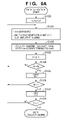
- FIG. 9A is a flowchart illustrating a data collection process according to the first embodiment.
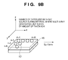
- FIG. 9B is a diagram illustrating an example of a two-dimensional array of X-ray sources according to the first embodiment.
- FIG. 10 is a flowchart illustrating a data reconstruction process according to the first embodiment.
- FIG. 11 is a diagram illustrating the XZ-plane of the imaging system according to a second embodiment.
- FIG. 1 is a diagram illustrating an example of the configuration of an X-ray imaging system according to a first embodiment.
- a multi X-ray generating unit 16 includes multiple X-ray sources 12 , serving as X-ray foci, that emit X-ray beams 13 , and collimaters 20 that form the X-ray beams 13 from the X-ray sources 12 primarily (see FIG. 2 ).
- Each X-ray source 12 is structured so as to generate X-rays by accelerating electrons from a cold cathode such as carbon nanotubes and causing them to collide with a target.
- the X-ray sources 12 are arranged two-dimensionally inside the multi X-ray generating unit 16 in, for example, a grid form that has 26 rows, 26 columns, and a grid pitch of 15 mm, resulting in 676 sources. Note, however, that the X-ray sources 12 are not limited to sources that utilize cold cathodes, and may instead utilize thermoelectron sources.
- Each X-ray beam 13 is formed secondarily by a slit unit 17 .
- the slit unit 17 is an assemblage of slit boards 21 , serving as slit members, provided for each of the X-ray sources 12 (this shall be described later with reference to FIG. 4 ).
- a slit board 21 is allocated to each individual X-ray source 12 .
- the slit boards 21 are fabricated and disposed so that the X-ray beams 13 that do not reach the detection surface of a two-dimensional detection unit 14 do not pass through the slit boards 21 . This is to prevent X-ray beams 13 that do not contribute to the imaging of a subject from being output.
- the cone-shaped X-ray beams 13 that enter into the slit boards 21 are transformed into multiple slice beams by multiple slits provided in the slit boards 21 .
- the formation of the X-ray beams by the slit unit 17 is not limited to such formation of slice beams; the X-ray beams may be formed into grid form as well.
- the X-ray percolation openings in the slit boards 21 are configured of grooves (slits), whereas when the X-ray beams 13 are to be formed in grid form, the X-ray percolation openings in the slit boards 21 are configured of rows of small holes.
- the slit unit 17 includes multiple slit boards 21 , each disposed opposite to its respective X-ray focus, and each of the multiple slit boards 21 includes multiple slits arranged in the X direction, or a first direction.
- Each of these multiple slits forms X-rays from opposing X-ray foci into a slice-formed X-ray beam whose longitudinal direction is the Y direction, or a second direction, which is different from the abovementioned first direction.
- the two-dimensional detection unit 14 detects the X-ray intensity of the X-ray beams formed by the slit means at the detection surface.
- the purpose of the slit unit 17 is to reduce scattering rays.
- This scattering ray removing grid is normally fabricated so as to include an imaging focus, and the imaging system is adjusted so that the focus of the X-ray beam and the imaging focus of the scattering ray removing grid match.
- an imaging system such as that described in the present embodiment, where multiple X-ray beam foci exist, such a scattering ray removing grid cannot be used.
- the lead slits of which the scattering ray removing grid is configured also have an adverse effect of dampening valid X-ray beams 13 as well.
- scattering rays are reduced through calculations.
- the X-ray beams 13 are formed in slice form or grid form, and a region into which X-rays do not enter is set in the two-dimensional detection unit 14 .
- scattering rays enter into even this region into which X-rays do not enter. It is thus possible for this region to detect only the scattering ray signals.
- the distribution of scattering rays across the entirety of the two-dimensional detection unit 14 can therefore be predicted through an interpolation process based on those scattering ray signals.
- the scattering rays can be reduced by subtracting the interpolated scattering ray signals from the signal values of the region into which the X-rays have entered as detected by the two-dimensional detection unit 14 . This process shall be described further with reference to FIG. 6 .
- Signal G 0 in FIG. 6 represents an ideal profile signal occurring when an X-ray beam 13 emitted from a single X-ray source passes through a slit in the slit unit 17 , passes through the subject, and is detected by the two-dimensional detection unit 14 . This also represents a signal obtained through ideal correction. However, the two-dimensional detection unit 14 actually outputs a signal value such as that represented by G 1 , due to scattering within the subject. Reducing, to zero, the regions of signal G 1 in which the direct components of the X-ray beam 13 enter results in signal G 2 ; signal G 2 represents only the scattering rays.
- Signal G 3 indicates the result of predicting scattering rays in the regions in which the direct components of the X-ray beam 13 enter based on signal G 2 . Note that it is necessary to carry out the prediction calculations having reduced the influence of regions nearby the regions in which the direct components of the X-ray beam 13 enter in signal G 2 .
- the range of nearby regions may be determined empirically, or may be determined based on the size of the signal value in the regions in which the direct components enter. Subtracting the predicted scattering signal G 3 from signal G 1 results in signal G 4 , which is a signal for which the scattering has been corrected.
- the scattering signal prediction can be performed by removing the regions in which the direct components of the X-ray beam 13 enter and carrying out polynomial interpolation, or by reducing the weight of the regions in which the direct components of the X-ray beam 13 enter and using a weighted average.
- the two-dimensional detection unit 14 is configured of multiple pixels disposed in grid form.
- each pixel (detector) is configured of a semiconductor detector, but other photoelectric conversion elements may be used.
- the pixel size of the detector is determined by the size of the lesion to be detected. Mammography for detecting calcifications of several millimeters requires a pixel size of approximately 100 microns, whereas chest imaging for detecting nodules of approximately 1 centimeter requires a pixel size of approximately 200 to 400 microns.
- the external size of the two-dimensional detection unit 14 is also dependent on the subject of the imaging. Mammography requires an external size of approximately 200 by 240 millimeters, whereas chest imaging requires a size of approximately 430 by 430 millimeters.
- a rectangular coordinate system 15 for imaging shall be described next.
- the X and Y axes represent the directions in which the grids of the multi X-ray generating unit 16 and the two-dimensional detection unit 14 are disposed, while the Z-axis represents the direction in which the X-ray beams 13 are emitted.
- the X-axis represents the direction in which the movement mechanisms of the multi X-ray generating unit 16 and the slit unit 17 slide those respective units.
- the mechanism for moving the multi X-ray generating unit 16 is a multi X-ray moving unit 18
- the mechanism for moving the slit unit 17 is a slit moving unit 19 .
- a physician observes an image s/he observes the image with the body axis of the person following the vertical direction. Because the human eye has a higher resolution in the horizontal direction, it is preferable to increase the resolution in the horizontal direction for diagnostic images as well. Accordingly, when, as shown in FIG. 1 , a human body is arranged so that the body axis direction and the X-axis direction match, X-ray beam slices that extend in the Y-axis direction are more advantageous in terms of resolution. In other words, an imaging system in which the X-ray beam slices extending in the Y-axis direction slide along the X-axis direction is desirable.
- FIG. 4 is a diagram viewing the slit unit 17 from the multi X-ray generating unit 16 that is positioned thereabove in the Z-axis direction.
- Multiple X-ray sources 12 are disposed in grid form in the multi X-ray generating unit 16 , and slit boards 21 , corresponding to each of the X-ray sources 12 , are provided in the slit unit 17 .
- the slit board 21 has a configuration in which multiple slits for shaping the X-ray beams 13 are provided in a lead plate that has high X-ray shielding efficiency.
- the slits When the X-ray beams 13 are to be formed in slice form, the slits have a rectangular shape extending in the Y direction, as shown in FIG. 4 .
- the slit board 21 has small square slits disposed in grid form.
- FIG. 2 illustrates the XZ-plane of the imaging system in the case where the slit unit 17 shown in FIG. 4 is used.
- three X-ray sources, or i, j, and k are illustrated as performing X-ray exposures at the same time; however, in reality, the X-ray sources 12 do not perform exposure at the same time. Rather, the sources are controlled so as to make switched exposures at high speeds. Meanwhile, during the switched exposures, the multi X-ray generating unit 16 and slit unit 17 slide relative to the two-dimensional detection unit 14 while maintaining their positions relative to each other, using the multi X-ray moving unit 18 and the slit moving unit 19 .
- the distance of the slide is the same as the grid pitch p of the multi X-ray generating unit 16 .
- imaging is performed multiple times during the period in which the multi X-ray generating unit 16 and the slit unit 17 slide an amount equivalent to the grid pitch p, making it possible to collect a proper amount of data among the multiple X-ray sources 12 .
- X-ray beams i 1 , j 1 , and k 1 are formed as parallel beams, and the interval between each X-ray beam is roughly the same as the grid pitch p.
- the reason for describing this as “roughly” p is that the multi X-ray generating unit 16 moves for a time ⁇ t, which depends on the exposure interval of the X-ray sources i, j, and k. In other words, assuming that the multi X-ray generating unit 16 moves ⁇ L during each exposure interval of ⁇ t, the interval between the X-ray beams is ⁇ L+p.
- the interval between the parallel beams can be reduced to approximately half, or p/2, by sliding the multi X-ray generating unit 16 so that the X-ray source i performs exposure from an intermediate point 28 in the path to the X-ray source j (see FIG. 7B ). Having the X-ray source i take N number of images at equal intervals while moving to the position of the X-ray source j makes it possible to reduce the interval between parallel beams to p/N. Through this, missing regions in the projection data in an image reconstruction space 27 (that is, data missing regions 31 (see FIG. 7A )) can be eliminated.
- the data missing regions 31 in the image reconstruction space 27 shall be described using FIGS. 7A and B. First, the following assumptions are made:
- the width of each X-ray beam in the X-axis direction at the position in the image reconstruction space 27 that is closest to the X-ray sources 12 is approximately 8 mm (0.5 mm ⁇ an enlargement rate of 15x+0.5 mm).
- the data in the portions of FIG. 7A indicated by crosshatching that is, the data missing regions 31
- FIG. 7B collecting data in the intermediate positions while sliding (the intermediate points 28 ) eliminates the data missing regions 31 .
- X-ray imaging may be executed at multiple positions while moving the multi X-ray generating unit 16 and the slit unit 17 by a predetermined pitch (grid pitch p).
- grid pitch p a predetermined pitch
- N ⁇ 1 additional exposures (images) at each part when the grid pitch p has been divided into N equal parts (where N is a natural number of 2 or more).
- Making N ⁇ 1 additional exposures in the grid pitch p interval contributes to an improvement in the S/N ratio in the projection data, in addition to preventing the occurrence of the spatial data missing regions 31 shown in FIG. 7A .
- FIG. 3 illustrates the XY-plane of the imaging system according to the first embodiment.
- the system is configured so that the entire width of the two-dimensional detection unit 14 in the XY-plane is irradiated by the X-ray beams 13 from each of the X-ray sources 12 .
- three X-ray sources, or i, j, and k are illustrated as performing X-ray exposures at the same time, as described earlier, in reality, the multiple X-ray sources 12 do not perform X-ray exposure at the same time. Rather, the sources make switched exposures at high speeds.
- FIG. 8 illustrates X-ray images formed upon the two-dimensional detection unit 14 by each X-ray source Xmn when switched exposure is carried out.
- the X-ray sources Xmn may perform fast-scanning in either the direction in the X-axis or the direction in the Y-axis.
- the data from X-ray sources 12 aligned in the X-axis direction (X-ray image data) is to be simultaneously back-projected as parallel data
- FIG. 5 is a block diagram illustrating an example of the configuration of an X-ray imaging system according to the first embodiment.
- the system of the first embodiment is controlled in its entirety by a computer 11 and a program (not shown). Instructions to start imaging a subject, instructions to reconstruct images, and displaying images are performed via an operational unit 22 . When an instruction to start imaging is made through the operational unit 22 , a control unit 23 commences control of the various units of which the imaging system is configured.
- control unit 23 outputs a command to a data collection unit 25 , placing the two-dimensional detection unit 14 in a data-collectable state, in accordance with an instruction to start imaging.
- the control unit 23 then outputs a command to a high-voltage supply unit 24 , placing the multiple X-ray sources 12 in a sequential exposure state.
- the control unit 23 causes the two-dimensional detection unit 14 to collect the X-ray projection data of the subject in synchronization with each exposure.
- the two-dimensional detection unit 14 digitizes the X-ray projection data and transfers the digitized data to the data collection unit 25 .
- the control unit 23 then controls the multi X-ray moving unit 18 and the slit moving unit 19 in parallel with the stated multiple exposure data collections, and slides the multi X-ray generating unit 16 and the slit unit 17 while maintaining their relative positional relationship.
- FIG. 9A is a flowchart illustrating a data collection process performed by the data collection unit 25 .
- fast-scanning is performed in the X-axis direction.
- M represents the number of X-ray sources 12 disposed in the X-axis direction
- N represents the number of X-ray sources 12 disposed in the Y-axis direction
- K represents the number of exposures by each X-ray source (Xmn) during the period in which the multi X-ray generating unit 16 slides by an amount Sp.
- the data collection unit 25 resets the variables k, m, and n to 1.
- step S 101 the data collection unit 25 commences data collection through X-ray exposure performed by the X-ray sources Xmn, and also starts sliding the multi X-ray generating unit 16 and the slit unit 17 .
- the slit unit 17 and the multi X-ray generating unit 16 slide with their relative positions being held the same.
- step S 102 an image Imnk resulting from an exposure Xmnk is stored in the data collection unit 25 .
- k represents the number of exposures by each X-ray source Xmn during the period in which the multi X-ray generating unit 16 slides by the amount Sp.
- steps S 103 and S 104 the X-ray images resulting from sequentially driving M X-ray sources aligned in the X-axis direction are collected first.
- This process is repeated until the Nth row.
- the variables m and n are reset to 1
- k is incremented by 1, and the process returns to step S 101 .
- This process is repeated K number of times during the slide interval (steps S 107 and S 108 ).
- the projection data stored in the data collection unit 25 is sequentially transferred to an image reconstruction unit 26 , and three-dimensional volume data is reconstructed.
- filter correction back-projection is appropriate for the image reconstruction, successive approximation may be used for the image reconstruction as well.
- a characteristic of the present embodiment is that the projection data makes up the parallel data. As shown in FIG. 2 , the X-ray beams i 1 , j 1 , and k 1 and the X-ray beams i 2 , j 2 , and k 2 each create respective parallel beams. Similarly, as shown in FIG.
- the transmitted X-ray data is formed locally upon the two-dimensional detection unit 14 .
- the data cut-out process is performed after the scattering ray correction shown in FIG. 6 . Performing the scattering ray correction prior to the data cut-out process and the data sorting process makes it possible to reduce the amount of memory required for processing and reduce the number of memory accesses.
- the data cut-out process is a process for geometrically cutting out a region that has been irradiated by X-rays from the overall image on the two-dimensional detection unit 14 , such as that exemplified by X 11 - 1 in FIG. 8 .
- the position of the portion Xmn-h that has been irradiated by X-rays within the overall image on the two-dimensional detection unit 14 can be calculated based on the X-ray exposure timing.
- the reconstruction of the parallel data is not limited to putting the X-ray slice images Imn-h corresponding to the X-ray slices Xmn-h in sequence.
- L number of X-ray slice images can be constructed by slicing the X-ray slice image Imn-h in the X-axis direction and putting the resulting slices in sequence.
- Increasing the number of divisions makes it possible to increase how parallel the parallel data is.
- the image Imn-h is fan data, and is thus not strictly parallel data even if spliced together. Breaking the data down to two-dimensional detector element rows makes it possible to obtain more complete parallel data.
- the set of X-ray slice images I 11 - 1 , I 21 - 1 , and I 31 - 1 , the set of X-ray slice images I 11 - 2 , I 21 - 2 , and I 31 - 2 , and the set of X-ray slice images I 12 - 1 , I 22 - 1 , and I 32 - 1 shown in FIG. 8 each make up parallel data.
- the data sorting process is a process that focuses upon that fact, splicing together sets on a set-by-set basis (a unit-by-unit basis for parallel data) into a single image.
- FIG. 10 is a flowchart illustrating the data reconstruction process described above.
- M represents the number of X-ray sources 12 disposed in the X-axis direction
- N represents the number of X-ray sources 12 disposed in the Y-axis direction
- K represents the number of exposures by each X-ray source Xmn during the period in which the multi X-ray generating unit 16 slides by an amount Sp.
- the image reconstruction unit 26 executes the scattering ray correction described in FIG. 6 taking the image Imnk stored in the data collection unit 25 as the processing unit (in FIG. 8 , for example, the X-ray slice images I 11 - 1 to I 11 - 6 are taken as the processing unit).
- step S 205 the region corresponding to the hth slit is cut out from a corrected image I′mnk, obtained by performing the scattering ray correction on the image Imnk, and is taken as I′mnk-h.
- step S 210 the X-ray image from the same hth slit is cut out for each X-ray source 12 aligned in the X direction (that is, the X-ray image obtained from a slice beam formed by slits whose relative positional relationship with the X-ray source match).
- step S 210 a single image is then spliced together, focusing on the fact that the cut-out images I′mnk-h make up parallel data.
- the image that has been spliced together is transferred to the image reconstruction unit 26 , after which filter correction back projection processing is carried out.
- the number of slit positions H is not limited to the actual number of slits, and may be an integral multiple of the actual slit number. Increasing the number of slit positions H can improve how parallel the spliced image is. Repeating the above processing until n>N results in the data being reconstructed.
- the image reconstruction unit 26 then back-projects the image transferred from the data collection unit 25 into an internal 3D memory space.
- the back-projection algorithm can employ a known technique. With filter correction back projection processing, a filtering process that removes the direct components of the image transferred from the data collection unit 25 is first performed, after which the data is back-projected based on a geometric system obtained through data collection. In the preceding descriptions, a reconstruction method that performs back-projection after the data has been sorted as parallel data has been discussed, but the reconstruction method is not limited thereto, and direct reconstruction, where the fan data is reconstructed as-is, may be used as well.
- the first embodiment it is possible to collect projection data of high density with respect to a 3D space that makes up a subject region.
- X-ray beams are simultaneously constructed in slit form, making it possible to improve the accuracy of scattering ray correction through image processing.
- enabling scattering ray correction through image processing eliminates the need for a scattering ray correction grid, making it possible to reduce the amount of radiation the subject (a patient) is exposed to.
- FIG. 11 is a diagram illustrating an example of the configuration of an X-ray imaging system according to a second embodiment.
- the multi X-ray generating unit 16 and the slit unit 17 slide with their relative positional relationships matching.
- the multi X-ray generating unit 16 and the slit unit 17 slide so that their relative positional relationships change.
- the purpose of moving these units so their relative positions change is to increase the number of directions for the X-ray beam slices that irradiate the subject, thereby improving the image quality of the reconstructed image.
- FIG. 11 is a diagram illustrating an example of the configuration of an X-ray imaging system according to a second embodiment.
- the multi X-ray generating unit 16 moves by an amount equivalent to the grid pitch p relative to the two-dimensional detection unit 14 , until the imaging stops.
- the slit unit 17 makes a round-trip pass relative to the multi X-ray generating unit 16 .
- X-ray exposure is carried out only in the two relative positions, or (1) and (2), it should be noted that there are multiple situations in which the multi X-ray generating unit 16 and the slit unit 17 have a different relative positional relationship. In other words, X-ray exposure can be performed in three or more relative positional relationships as well. Note that the movement is equivalent to the pitch interval in the X direction of the slits. Furthermore, because it is difficult to ensure that the relative positions of the multi X-ray generating unit 16 and the slit unit 17 are the same for each X-ray source 12 , the direct method for back-projecting each projection image as-is is used as the reconstruction algorithm. Finally, the variation of the relative positions is not limited to the direction in which the multi X-ray generating unit 16 slides, the projection data from different irradiation angles can be collected even if the variation occurs in the direction perpendicular to the slide direction.
- the second embodiment it is possible to improve the number of the various irradiation angles with respect to a 3D space that makes up a subject region, making it possible to improve the resolution of the reconstructed image and the S/N ratio.
- Embodiments of the present invention have been described in detail above, but the present invention can take the form of a system, apparatus, method, program, storage medium, and so on. Specifically, the present invention may be applied to a system configured of multiple devices or to an apparatus configured of a single device.
- the supplied program is a computer program that corresponds to the flowchart indicated in the drawings in the embodiments.
- the program code itself installed in a computer so as to realize the functional processing of the present invention through a computer, also realizes the present invention.
- the computer program itself for realizing the functional processing of the present invention, is also included within the scope of the present invention.
- a program executed through an interpreter or object code, script data supplied to an OS, or the like may be used, as long as it has the functions of the program.
- Examples of the a computer readable storage medium that can be used to supply the computer program include Floppy® disks, hard disks, optical disks, magneto-optical disks, MOs, CD-ROMs, CD-Rs, CD-RWs, magnetic tape, non-volatile memory cards, ROMs, and DVDs (DVD-ROMs, DVD-Rs).
- a browser of a client computer to connect to an Internet homepage and downloading the computer program of the present invention to a storage medium such as a hard disk can be given as another method for supplying the program.
- the downloaded program may be a compressed file including a function for automatic installation.
- this method may be realized by dividing the program code that makes up the program of the present invention into multiple files and downloading each file from different homepages.
- a WWW server that allows multiple users to download the program files for realizing the functional processing of the present invention through a computer also falls within the scope of the present invention.
- the program of the present invention may be encrypted, stored in a storage medium such as a CD-ROM, and distributed to users.
- a user that has cleared a predetermined condition is allowed to download key information for removing the cryptography from a homepage via the Internet, use the key information to decrypt the program, and install the program on a computer.
- the functions of the embodiments may be realized, in addition to through the execution of a loaded program using a computer, through cooperation with an OS or the like running on the computer based on instructions of the program.
- the OS or the like performs part or all of the actual processing, and the functions of the above-described embodiments are realized by that processing.
- the functions of the aforementioned embodiments may be partially or completely implemented by writing the program that has been read out from the storage medium into the memory of a function expansion board installed in a computer or a function expansion unit connected to a computer.
- a CPU or the like included in the function expansion board or the function expansion unit performs part or all of the actual processing based on the instructions of the program.
Applications Claiming Priority (2)
| Application Number | Priority Date | Filing Date | Title |
|---|---|---|---|
| JP2008068355A JP5398157B2 (ja) | 2008-03-17 | 2008-03-17 | X線撮影装置及びその制御方法 |
| JP2008-068355 | 2008-03-17 |
Publications (2)
| Publication Number | Publication Date |
|---|---|
| US20090232272A1 US20090232272A1 (en) | 2009-09-17 |
| US7945015B2 true US7945015B2 (en) | 2011-05-17 |
Family
ID=41063029
Family Applications (1)
| Application Number | Title | Priority Date | Filing Date |
|---|---|---|---|
| US12/395,773 Expired - Fee Related US7945015B2 (en) | 2008-03-17 | 2009-03-02 | X-ray imaging apparatus and control method thereof |
Country Status (3)
| Country | Link |
|---|---|
| US (1) | US7945015B2 (ja) |
| JP (1) | JP5398157B2 (ja) |
| CN (2) | CN101536912B (ja) |
Cited By (8)
| Publication number | Priority date | Publication date | Assignee | Title |
|---|---|---|---|---|
| US8611500B2 (en) | 2010-07-30 | 2013-12-17 | Canon Kabushiki Kaisha | X-ray imaging apparatus and measurement method |
| US8817949B2 (en) | 2011-07-25 | 2014-08-26 | Canon Kabushiki Kaisha | Radiographic apparatus and control method therefor |
| US9020098B2 (en) | 2012-03-13 | 2015-04-28 | Canon Kabushiki Kaisha | Radiation imaging apparatus |
| US20150251018A1 (en) * | 2014-03-10 | 2015-09-10 | Fujifilm Corporation | Radiation image processing apparatus, method, and medium |
| US9402586B2 (en) | 2011-12-21 | 2016-08-02 | Canon Kabushiki Kaisha | Stereo X-ray imaging apparatus and stereo X-ray imaging method |
| US20170245814A1 (en) * | 2014-10-16 | 2017-08-31 | Adaptix Ltd | A method of designing an x-ray emitter panel |
| US10383587B2 (en) | 2015-06-30 | 2019-08-20 | Canon Kabushiki Kaisha | Radiation CT apparatus and method of controlling the same |
| US20200182807A1 (en) * | 2018-12-10 | 2020-06-11 | KUB Technologies, Inc. | System and method for cabinet x-ray systems with stationary x-ray source array |
Families Citing this family (23)
| Publication number | Priority date | Publication date | Assignee | Title |
|---|---|---|---|---|
| JP5294653B2 (ja) * | 2008-02-28 | 2013-09-18 | キヤノン株式会社 | マルチx線発生装置及びx線撮影装置 |
| JP5361336B2 (ja) * | 2008-11-06 | 2013-12-04 | キヤノン株式会社 | X線乳房撮影装置 |
| JP5247363B2 (ja) * | 2008-11-11 | 2013-07-24 | キヤノン株式会社 | X線撮影装置 |
| JP5576631B2 (ja) * | 2009-09-09 | 2014-08-20 | キヤノン株式会社 | 放射線撮影装置、放射線撮影方法、及びプログラム |
| JP2012066062A (ja) * | 2010-08-24 | 2012-04-05 | Fujifilm Corp | 放射線撮影システム及び放射線撮影方法 |
| US9424958B2 (en) * | 2011-06-06 | 2016-08-23 | Koninklijke Philips N.V. | Multiple focal spot X-ray radiation filtering |
| EP2775804A4 (en) * | 2011-11-02 | 2015-08-05 | Fuji Film Corp | RADIATION EMISSION DEVICE, RADIATION EMISSION METHOD, AND PROGRAM STORAGE MEDIUM |
| WO2014034244A1 (ja) * | 2012-08-27 | 2014-03-06 | ソニー株式会社 | X線出力装置 |
| JP6395373B2 (ja) * | 2013-11-29 | 2018-09-26 | キヤノン株式会社 | 放射線発生ユニットおよび放射線撮影装置 |
| GB2533632B (en) * | 2014-12-24 | 2018-01-03 | Gen Electric | Method and system for obtaining low dose tomosynthesis and material decomposition images |
| CN105310708A (zh) * | 2015-09-30 | 2016-02-10 | 李光磊 | 骨外科疾病全身诊断装置 |
| CN108882905B (zh) | 2016-03-25 | 2022-08-23 | 卡尔斯特里姆保健公司 | 具有弯曲检测器的cbct成像系统 |
| KR101875847B1 (ko) * | 2016-12-07 | 2018-07-06 | 주식회사 디알텍 | 방사선 촬영 장치 및 이를 이용한 방사선 촬영 방법 |
| US10888286B2 (en) * | 2017-03-22 | 2021-01-12 | Carestream Health, Inc. | CBCT imaging system with curved detector and curved grid |
| EP3459463A1 (en) * | 2017-09-26 | 2019-03-27 | Koninklijke Philips N.V. | Device and method for determining a volume of projection of a dual-axis computed tomography system |
| JP2021518217A (ja) * | 2018-03-19 | 2021-08-02 | センスラボ エルエルシーXenselab, Llc | X線断層撮影法 |
| JP6855406B2 (ja) * | 2018-03-23 | 2021-04-07 | 富士フイルム株式会社 | 画像処理装置、放射線画像撮影システム、画像処理方法、及び画像処理プログラム |
| JP2019180906A (ja) | 2018-04-11 | 2019-10-24 | 富士フイルム株式会社 | 画像処理装置、放射線画像撮影システム、画像処理方法、及び画像処理プログラム |
| CN109991247A (zh) * | 2018-11-27 | 2019-07-09 | 姚智伟 | 基于平板x射线源阵列的x射线成像系统及扫描成像方法 |
| JP7221825B2 (ja) * | 2019-07-26 | 2023-02-14 | 富士フイルム株式会社 | トモシンセシス撮影制御装置、トモシンセシス撮影制御装置の作動方法、トモシンセシス撮影制御装置の作動プログラム |
| EP3832690A1 (en) * | 2019-12-05 | 2021-06-09 | Koninklijke Philips N.V. | Estimation of full-field scattering for dax imaging |
| WO2021258785A1 (en) * | 2020-06-22 | 2021-12-30 | Shanghai United Imaging Healthcare Co., Ltd. | Systems and methods for x-ray imaging |
| WO2022156160A1 (zh) * | 2021-01-22 | 2022-07-28 | 上海涛影医疗科技有限公司 | 一种通过狭缝扫描的成像设备 |
Citations (5)
| Publication number | Priority date | Publication date | Assignee | Title |
|---|---|---|---|---|
| JP2000060835A (ja) | 1998-08-25 | 2000-02-29 | Fuji Photo Film Co Ltd | 放射線画像検出装置 |
| JP2004089445A (ja) | 2002-08-30 | 2004-03-25 | Konica Minolta Holdings Inc | X線発生装置およびx線画像撮像システム |
| US20070280408A1 (en) * | 2006-04-14 | 2007-12-06 | Tiezhi Zhang | Scanning slot cone-beam computed tomography and scanning focus spot cone-beam computed tomography |
| US20090232270A1 (en) | 2008-02-28 | 2009-09-17 | Canon Kabushiki Kaisha | Multi x-ray generating apparatus and x-ray imaging apparatus |
| US20090316860A1 (en) | 2006-03-03 | 2009-12-24 | Cannon Kabushiki Kaisha | Multi x-ray generator and multi x-ray imaging apparatus |
Family Cites Families (7)
| Publication number | Priority date | Publication date | Assignee | Title |
|---|---|---|---|---|
| JPH05269122A (ja) * | 1992-03-26 | 1993-10-19 | Toshiba Corp | X線ct装置 |
| JPH0614911A (ja) * | 1992-07-02 | 1994-01-25 | Toshiba Corp | X線診断方法及びその装置 |
| JP2005245559A (ja) * | 2004-03-02 | 2005-09-15 | Ge Medical Systems Global Technology Co Llc | X線ct装置およびx線装置 |
| US7542540B2 (en) * | 2005-07-15 | 2009-06-02 | Kabushiki Kaisha Toshiba | X-ray CT apparatus |
| JP2007044496A (ja) * | 2005-07-15 | 2007-02-22 | Toshiba Corp | X線ct装置 |
| WO2007034352A2 (en) * | 2005-09-19 | 2007-03-29 | Philips Intellectual Property & Standards Gmbh | Grid for selective absorption of electromagnetic radiation and method for its manufacture |
| JP2007195612A (ja) * | 2006-01-24 | 2007-08-09 | Shimadzu Corp | X線撮像装置 |
-
2008
- 2008-03-17 JP JP2008068355A patent/JP5398157B2/ja not_active Expired - Fee Related
-
2009
- 2009-03-02 US US12/395,773 patent/US7945015B2/en not_active Expired - Fee Related
- 2009-03-17 CN CN2009101194978A patent/CN101536912B/zh not_active Expired - Fee Related
- 2009-03-17 CN CN2011101652085A patent/CN102266234B/zh not_active Expired - Fee Related
Patent Citations (5)
| Publication number | Priority date | Publication date | Assignee | Title |
|---|---|---|---|---|
| JP2000060835A (ja) | 1998-08-25 | 2000-02-29 | Fuji Photo Film Co Ltd | 放射線画像検出装置 |
| JP2004089445A (ja) | 2002-08-30 | 2004-03-25 | Konica Minolta Holdings Inc | X線発生装置およびx線画像撮像システム |
| US20090316860A1 (en) | 2006-03-03 | 2009-12-24 | Cannon Kabushiki Kaisha | Multi x-ray generator and multi x-ray imaging apparatus |
| US20070280408A1 (en) * | 2006-04-14 | 2007-12-06 | Tiezhi Zhang | Scanning slot cone-beam computed tomography and scanning focus spot cone-beam computed tomography |
| US20090232270A1 (en) | 2008-02-28 | 2009-09-17 | Canon Kabushiki Kaisha | Multi x-ray generating apparatus and x-ray imaging apparatus |
Cited By (12)
| Publication number | Priority date | Publication date | Assignee | Title |
|---|---|---|---|---|
| US8611500B2 (en) | 2010-07-30 | 2013-12-17 | Canon Kabushiki Kaisha | X-ray imaging apparatus and measurement method |
| US8948342B2 (en) | 2010-07-30 | 2015-02-03 | Canon Kabushiki Kaisha | X-ray imaging apparatus and measurement method |
| US8817949B2 (en) | 2011-07-25 | 2014-08-26 | Canon Kabushiki Kaisha | Radiographic apparatus and control method therefor |
| US9402586B2 (en) | 2011-12-21 | 2016-08-02 | Canon Kabushiki Kaisha | Stereo X-ray imaging apparatus and stereo X-ray imaging method |
| US9020098B2 (en) | 2012-03-13 | 2015-04-28 | Canon Kabushiki Kaisha | Radiation imaging apparatus |
| US20150251018A1 (en) * | 2014-03-10 | 2015-09-10 | Fujifilm Corporation | Radiation image processing apparatus, method, and medium |
| US10045746B2 (en) * | 2014-03-10 | 2018-08-14 | Fujifilm Corporation | Radiation image processing apparatus, method, and medium |
| US20170245814A1 (en) * | 2014-10-16 | 2017-08-31 | Adaptix Ltd | A method of designing an x-ray emitter panel |
| US10524743B2 (en) * | 2014-10-16 | 2020-01-07 | Adaptix Ltd. | Method of designing an X-ray emitter panel |
| US10383587B2 (en) | 2015-06-30 | 2019-08-20 | Canon Kabushiki Kaisha | Radiation CT apparatus and method of controlling the same |
| US20200182807A1 (en) * | 2018-12-10 | 2020-06-11 | KUB Technologies, Inc. | System and method for cabinet x-ray systems with stationary x-ray source array |
| US11020066B2 (en) * | 2018-12-10 | 2021-06-01 | KUB Technologies, Inc. | System and method for cabinet x-ray systems with stationary x-ray source array |
Also Published As
| Publication number | Publication date |
|---|---|
| CN101536912A (zh) | 2009-09-23 |
| US20090232272A1 (en) | 2009-09-17 |
| CN102266234B (zh) | 2013-06-05 |
| JP5398157B2 (ja) | 2014-01-29 |
| CN101536912B (zh) | 2011-07-20 |
| JP2009219708A (ja) | 2009-10-01 |
| CN102266234A (zh) | 2011-12-07 |
Similar Documents
| Publication | Publication Date | Title |
|---|---|---|
| US7945015B2 (en) | X-ray imaging apparatus and control method thereof | |
| JP6242631B2 (ja) | 医用画像処理装置及びx線コンピュータ断層撮影装置 | |
| JP6571313B2 (ja) | 医用画像診断装置及び制御方法 | |
| EP2446821B1 (en) | Dynamic collimator for wide coverage and low dose cardiac CT imaging | |
| US20140177794A1 (en) | System and method for focal spot deflection | |
| JP2005013738A (ja) | トモシンセシス用途における対象物を走査するためのシステム及び方法 | |
| JP2005087618A (ja) | 放射線計算断層画像装置およびそれに用いる放射線検出器 | |
| JP2005087588A (ja) | 放射線計算断層画像装置および断層像データ生成方法 | |
| JP2008012206A (ja) | X線断層撮影装置 | |
| JP2007185358A (ja) | X線ct装置 | |
| JP2010540063A (ja) | コンピュータ断層撮影装置 | |
| EP3161792B1 (en) | Ct imaging apparatus with sparse angular sampling | |
| JP6985047B2 (ja) | X線ct装置 | |
| JP2002136510A (ja) | カバー範囲を拡大させたミリメートル未満のctスライスを得るための方法及び装置 | |
| JP5723432B2 (ja) | X線撮影装置及びその制御方法 | |
| JP2011227028A (ja) | 断層像再構成方法およびx線ct装置 | |
| JP2007151849A (ja) | X線ct撮影方法およびx線ct装置 | |
| CN100435732C (zh) | 图像重构方法及x射线ct装置 | |
| JP2004208799A (ja) | 透過x線データ獲得装置およびx線ct装置 | |
| EP3143591A1 (en) | Computerized tomographic image exposure and reconstruction method | |
| EP4087487B1 (en) | X-ray imaging systems for reducing artefacts associated with anti-scatter grids and methods of operating the same | |
| JP4610795B2 (ja) | スライス厚決定方法、スライス厚決定装置、プログラムおよびx線ct装置 | |
| US20230320686A1 (en) | Systems and methods for computed tomography | |
| JP4623858B2 (ja) | X線ct装置 | |
| JP6865543B2 (ja) | X線ct装置及びプログラム |
Legal Events
| Date | Code | Title | Description |
|---|---|---|---|
| AS | Assignment |
Owner name: CANON KABUSHIKI KAISHA, JAPAN Free format text: ASSIGNMENT OF ASSIGNORS INTEREST;ASSIGNORS:TSUJII, OSAMU;TSUCHIYA, KEIJI;OKUNUKI, MASAHIKO;REEL/FRAME:022437/0235;SIGNING DATES FROM 20090224 TO 20090226 Owner name: CANON KABUSHIKI KAISHA, JAPAN Free format text: ASSIGNMENT OF ASSIGNORS INTEREST;ASSIGNORS:TSUJII, OSAMU;TSUCHIYA, KEIJI;OKUNUKI, MASAHIKO;SIGNING DATES FROM 20090224 TO 20090226;REEL/FRAME:022437/0235 |
|
| STCF | Information on status: patent grant |
Free format text: PATENTED CASE |
|
| FPAY | Fee payment |
Year of fee payment: 4 |
|
| FEPP | Fee payment procedure |
Free format text: MAINTENANCE FEE REMINDER MAILED (ORIGINAL EVENT CODE: REM.); ENTITY STATUS OF PATENT OWNER: LARGE ENTITY |
|
| LAPS | Lapse for failure to pay maintenance fees |
Free format text: PATENT EXPIRED FOR FAILURE TO PAY MAINTENANCE FEES (ORIGINAL EVENT CODE: EXP.); ENTITY STATUS OF PATENT OWNER: LARGE ENTITY |
|
| STCH | Information on status: patent discontinuation |
Free format text: PATENT EXPIRED DUE TO NONPAYMENT OF MAINTENANCE FEES UNDER 37 CFR 1.362 |
|
| FP | Expired due to failure to pay maintenance fee |
Effective date: 20190517 |