US7922601B2 - Golf club head - Google Patents
Golf club head Download PDFInfo
- Publication number
- US7922601B2 US7922601B2 US12/355,326 US35532609A US7922601B2 US 7922601 B2 US7922601 B2 US 7922601B2 US 35532609 A US35532609 A US 35532609A US 7922601 B2 US7922601 B2 US 7922601B2
- Authority
- US
- United States
- Prior art keywords
- golf club
- club head
- face
- stair
- head according
- Prior art date
- Legal status (The legal status is an assumption and is not a legal conclusion. Google has not performed a legal analysis and makes no representation as to the accuracy of the status listed.)
- Active
Links
Images


Classifications
-
- A—HUMAN NECESSITIES
- A63—SPORTS; GAMES; AMUSEMENTS
- A63B—APPARATUS FOR PHYSICAL TRAINING, GYMNASTICS, SWIMMING, CLIMBING, OR FENCING; BALL GAMES; TRAINING EQUIPMENT
- A63B53/00—Golf clubs
- A63B53/04—Heads
- A63B53/047—Heads iron-type
-
- A—HUMAN NECESSITIES
- A63—SPORTS; GAMES; AMUSEMENTS
- A63B—APPARATUS FOR PHYSICAL TRAINING, GYMNASTICS, SWIMMING, CLIMBING, OR FENCING; BALL GAMES; TRAINING EQUIPMENT
- A63B53/00—Golf clubs
- A63B53/04—Heads
- A63B53/0408—Heads characterised by specific dimensions, e.g. thickness
-
- A—HUMAN NECESSITIES
- A63—SPORTS; GAMES; AMUSEMENTS
- A63B—APPARATUS FOR PHYSICAL TRAINING, GYMNASTICS, SWIMMING, CLIMBING, OR FENCING; BALL GAMES; TRAINING EQUIPMENT
- A63B53/00—Golf clubs
- A63B53/04—Heads
- A63B53/0445—Details of grooves or the like on the impact surface
-
- A—HUMAN NECESSITIES
- A63—SPORTS; GAMES; AMUSEMENTS
- A63B—APPARATUS FOR PHYSICAL TRAINING, GYMNASTICS, SWIMMING, CLIMBING, OR FENCING; BALL GAMES; TRAINING EQUIPMENT
- A63B53/00—Golf clubs
- A63B53/04—Heads
- A63B53/0466—Heads wood-type
Definitions
- the present invention relates to a golf club head and, more particularly, to score lines on the face.
- a plurality of straight grooves are formed parallel to each other in the toe-and-heel direction (e.g., Japanese Patent Laid-Open No. 10-248974). These grooves are called score lines, marking lines, face lines, or the like (to be referred to as score lines in this specification). These score lines have an effect of increasing the backspin amount of a shot.
- grass gets in between the face and a golf ball and the backspin amount of a shot decreases in the case of a shot from the rough. Therefore, it is desired to suppress a significant decrease in the backspin amount of a shot in the case of a shot from the rough.
- a golf club head comprising a plurality of score lines on a face, and a stair-shaped portion comprising a plurality of steps arranged on a side wall of said score line from a face side end in a depth direction of said score line.
- FIG. 1 is a view showing the outer appearance of a golf club head 1 according an embodiment of the present invention
- FIG. 2 shows a sectional view of a score line 20 in a direction perpendicular to the longitudinal direction (toe-and-heel direction) and its partially enlarged view;
- FIG. 3 is a view for explaining a two-circle rule
- FIG. 4 is a view for explaining an area rule
- FIGS. 5A to 5C are views for explaining examples of the method of forming the score lines 20 ;
- FIG. 6 is a table showing the specifications of score lines of Comparative Examples 1 and 2 and an example, the test results, and the conformance to the two-circle rule;
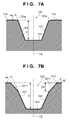
- FIG. 7A is a sectional view of a score line 120 of Comparative Example 1
- FIG. 7B is a sectional view of a score line 320 of Comparative Example 2.
- FIG. 1 is a view showing the outer appearance of a golf club head 1 according to an embodiment of the present invention.
- FIG. 1 shows an example in which the present invention is applied to an iron golf club head.
- the present invention is suitable for iron golf club heads, and particularly for middle iron golf club heads, short iron golf club heads, and wedge golf club heads. More specifically, the present invention is suitable for golf club heads with loft angles of 25° to 70° (both inclusive) and head weights of 240 g to 320 g (both inclusive). However, the present invention is also applicable to wood or utility (hybrid) golf club heads.
- the golf club head 1 has a plurality of score lines 20 formed on its face (hitting surface) 10 .
- the respective score lines 20 are straight grooves extending in the toe-and-heel direction and parallel to each other.
- the respective score lines 20 are arranged at an equal interval (equal pitch) but they may be arranged at different intervals.
- FIG. 2 shows a sectional view of the score line 20 in a direction perpendicular to the longitudinal direction (toe-and-heel direction) and its partially enlarged view (an enlarged view of a stair-shaped portion 211 ).
- the cross-sectional shapes of the score lines 20 are the same except in two end portions in the longitudinal direction.
- the score lines 20 have the same cross-sectional shape.
- the score line 20 has a pair of side walls 21 and a bottom wall 22 .
- the cross-sectional shape of the score line 20 is symmetric with regard to its center line CL.
- the cross-sectional shape of the score line 20 is almost trapezoidal, but it may be a V-shape or U-shape.
- a depth D is the length from the face 10 to the bottom wall 22 .
- the side wall 21 has the stair-shaped portion 211 including a plurality of steps arranged from the end of the side wall 21 on the face 10 side in the depth direction of the score line 20 .
- the number of steps of the stair-shaped portion 211 is seven in this embodiment, but the number of steps can be two or more.
- a plurality of edges Po is formed in the periphery of the boundary portion of the score line 20 and face 10 .
- these edges Po touch the golf ball, its backspin amount can be increased.
- the presence of a plurality of the edges Po improves the frictional force with respect to the golf ball. Accordingly, it is possible to suppress a significant decrease in the backspin amount.
- a plurality of the edges Po is positioned on a straight line L 1 .
- An angle ⁇ b is the angle between the straight line L 1 and face 10 .
- An angle ⁇ a is the angle between the face 10 and a portion of the side wall 21 without the stair-shaped portion 211 .
- a surface Sf of each step of the stair-shaped portion 211 is parallel to the face 10 , but it may not be parallel to the face 10 .
- the stair-shaped portion 211 is processed more easily when the surface Sf is set to be parallel to the face 10 .
- the step difference Sh exceeds a certain size, an amount by which a golf ball is caught does not change any longer. On the contrary, it may take time to form the steps depending on the processing method.
- the step difference Sh is preferably 30 ⁇ m or less. In this embodiment, the step difference Sh is the same in all steps, but it may differ in the respective steps.
- An area Ds indicates the area of the stair-shaped portion 211 in the depth direction of the score line 20 , which is the length from the face 10 to the deepest step of the stair-shaped portion 211 .
- the area Ds is preferably 1 ⁇ 2 or less of a depth D of the score line 20 , and more preferably 1 ⁇ 3 or less. Even if the area Ds is larger than 1 ⁇ 2 of the depth D, the number of the edges Po that touch a golf ball upon hitting does not largely change and a change in the backspin amount is small. On the contrary, since the number of steps of the stair-shaped portion 211 increases, it may take time to process the steps depending on the processing method. When the area Ds is set to 1 ⁇ 3 or less of the depth D, it is possible to reduce time required for processing the stair-shaped portion 211 while maintaining the effect of increasing the backspin amount.
- each edge of a score line must be positioned within a virtual circle with a radius of 0.011 inches concentric with a virtual circle with a radius of 0.010 inches which internally touches the side surface of the score line and the face (to be referred to as a two-circle rule, hereinafter).
- score lines are designed to satisfy the two-circle rule.
- FIG. 3 is a view for explaining the two-circle rule and shows an example in which the score line 20 is formed to satisfy the two-circle rule.
- a virtual circle C 1 is a circle with a radius of 0.010 inches.
- the position of the virtual circle C 1 is determined as follows. That is, assume that the virtual circle C 1 is virtually moved in a direction (a direction indicated by an arrow D 1 ) from a position away from the score line 20 to get close to the score line while the virtual circle C 1 internally touches the face 10 .
- the virtual circle C 1 first touches any one of edges Pi each on the opposite side of the edge Po (see FIG. 2 ) of each step of the stair-shaped portion 211 or a portion of the side wall 21 without the stair-shaped portion 211 .
- the example in FIG. 3 shows a case in which, of a plurality of edges Pi and a portion of the side wall 21 without the stair-shaped portion 211 , the virtual circle C 1 first touches an edge Pia.
- a virtual circle C 2 is an edge with a radius of 0.011 inches which is concentric with the virtual circle C 1 .
- the edge of the score line 20 (the boundary portion of the stair-shaped portion 211 and face 10 ) is positioned within the virtual circle C 2 , this example conforms to the two-circle rule.
- a width W and cross section area A of a score line and a distance S of adjacent score lines need to satisfy the cross section area A(inch 2 )/(W(inch)+S(inch)) ⁇ (to be referred to as an area rule, hereinafter).
- the metric system expresses the cross section area A(mm 2 )/(W(mm)+S(mm)) ⁇ 0.0762.
- score lines are designed to satisfy the area rule as well.
- FIG. 4 is a view for explaining the area rule.
- the width W of the score line 20 indicates the width measured based on the so-called 30 degrees measurement rule. That is, the width W indicates the distance between the contact points of the respective virtual lines inclined at an angle of 30° with respect to the face 10 and the respective edges of the score line 20 .
- the distance S between the score lines 20 indicates the distance between the contact points of the respective virtual lines inclined at an angle of 30° with respect to the face 10 and the respective edges of the score lines 20 adjacent to one another.
- the cross section area A indicates the cross-sectional area in a direction perpendicular to the longitudinal direction (toe-and-heel direction) of the score line 20 .
- the method of forming the score lines 20 will be described next.
- the score lines 20 may be formed such that grooves without the stair-shaped portions 211 are formed by a first process and then the stair-shaped portions 211 are formed by a second process.
- the first process may be different from the second process.
- the first process may be a forging process and the second process may be a cutting process.
- the stair-shaped portion 211 since the stair-shaped portion 211 includes fine steps, it is preferably formed by a cutting process.
- FIGS. 5A to 5C are views for explaining examples of the method of forming the score lines 20 , in which an NC (numerically controlled) milling machine is used.
- a golf club head 1 ′ without the score lines 20 is fixed to the NC milling machine via a jig 2 .
- a face member which forms the face 10 and the head body may be prepared as separate members and joined together.
- the face member is fixed to the NC milling machine to form the score lines 20 .
- the NC milling machine includes a spindle 4 which is rotatably driven around the axis Z.
- a cutting tool (end mill) 5 is attached to the lower end of the spindle 4 .
- the spindle 4 After setting the plane coordinates of the face 10 in the NC milling machine, the spindle 4 is rotatably driven.
- the face 10 (golf club head 1 ′) or cutting tool 5 is moved relatively in the formation direction of the score lines 20 to cut the face 10 so that grooves without the stair-shaped portions 211 are formed by the first process. Then, the cutting tool 5 is changed as needed and the stair-shaped portions 211 are processed.
- FIG. 5B shows an example of a state during processing of the stair-shaped portions 211 .
- FIG. 5B illustrates a case in which the stair-shaped portions 211 are formed one by one for the side walls 21 of a groove 20 ′ formed by the first process.
- FIG. 5C shows another example of a state during processing of the stair-shaped portions 211 .
- FIG. 5C illustrates a case in which the stair-shaped portions 211 are simultaneously formed in a pair of the side walls 21 of the groove 20 ′ formed by the first process.
- the surface hardness of the face 10 may decrease and the face 10 may be easily worn out. For this reason, it is desirable to perform treatment for increasing the surface hardness of the face 10 after forming the stair-shaped portion 211 .
- This treatment may be performed for the entire face 10 , or may be performed only for the vicinities of the stair-shaped portions 211 .
- surface treatment cementing, nitriding, soft nitriding, PVD (Physical Vepor Deposition), ion plating, DLC (Diamond Like Carbon) treatment, plating, or the like is available.
- surface treatment such as cementing or nitriding is preferable which reforms a surface without forming another metal layer on it.
- FIG. 6 is a table showing the specifications of score lines of Comparative Examples 1 and 2 and the example, the test results, and the conformance to the two-circle rule. All golf club heads of Comparative Examples 1 and 2 and the example were wedges with a loft angle of 58°.
- the stair-shaped portions were formed as shown in FIG. 2 .
- the number of steps of the stair-shaped portion was set to seven and the step difference Sh of each step was set to 20 ⁇ m.
- FIG. 7A shows the cross-sectional shape of a score line 120 of Comparative Example 1
- FIG. 7B shows the cross-sectional shape of a score line 220 of Comparative Example 2.
- the score line 120 of Comparative Example 1 has a pair of side walls 121 and a bottom wall 122 .
- the cross-sectional shape of the score line 120 is symmetric with regard to its virtual center line CL.
- the side walls 121 are formed to be flat, and each of edges 121 a of the score line 120 is rounded to have a radius of 0.05 mm.
- a depth D is the length from a face 110 to the bottom wall 122
- an angle ⁇ a is the angle between the face 110 and side wall 121 .
- the score line 320 of Comparative Example 2 has a pair of side walls 321 and a bottom wall 322 .
- the cross-sectional shape of the score line 320 is symmetric with regard to its center line CL.
- a flat portion 3211 with an angle of inclination different from that of the side wall 321 is formed in an area Ds′ ranging from the face 310 in the depth direction of the score line 320 .
- a depth D is the length from the face 310 to the bottom wall 322 .
- An angle ⁇ a is the angle between the face 310 and a portion of the side wall 321 other than the flat portion 3211 .
- An angle ⁇ b′ is the angle between the face 310 and the flat portion 3211 .
- angle ⁇ a indicates the angles ⁇ a shown in FIGS. 2 , 7 A, and 7 B.
- Angle ⁇ b indicates the angle ⁇ b shown in FIG. 2 , which is the angle between the face 10 and the straight line (L 1 ) passing through each edge (Po) of the stair-shaped portion. That is, the score line of the example has an arrangement in which the edges (Po) of the stair-shaped portion are positioned on the same straight line.
- Angle ⁇ b′ indicates the angle ⁇ b′ shown in FIG. 7B .
- “Width W” indicates the width of the score line measured based on the 30 degrees measurement rule described above with reference to FIG. 4 .
- “Depth D” indicates the depths D shown in FIGS. 2 , 7 A, and 7 B.
- “Area Ds” indicates the area Ds shown in FIG. 2 , which is the area of the stair-shaped portion in the depth direction of the score line.
- “Area Ds′” indicates the area Ds′ shown in FIG. 7B .
- the example and Comparative Example 2 are different only in presence/absence of a stair-shaped portion.
- the example corresponds to a golf club head obtained by forming stair-shaped portions respectively in the flat portions 3211 of Comparative Example 2.
- “Conformance to two-circle rule” indicates whether the golf club head conforms to the above-described two-circle rule. “NG” means “not conform” and “OK” means “conform”. Only Comparative Example 1 does not conform to the two-circle rule.
- backspin amount shows the average values of the actually measured values of backspin amounts obtained from a plurality of shots from the fairway and rough.
- BSf be the value shown in “backspin amount” in the case of a shot from the fairway
- BSr be the value shown in “backspin amount” in case of a shot from the rough
- Percentage of decrease is an index indicating a degree of decrease in the backspin amount of a shot from the rough with respect to a shot from the fairway. The smaller the absolute value, the smaller a decrease in the backspin amount in the case of a shot from the rough.
Landscapes
- Health & Medical Sciences (AREA)
- General Health & Medical Sciences (AREA)
- Physical Education & Sports Medicine (AREA)
- Golf Clubs (AREA)
Applications Claiming Priority (2)
| Application Number | Priority Date | Filing Date | Title |
|---|---|---|---|
| JP2008226310A JP5296461B2 (ja) | 2008-09-03 | 2008-09-03 | ゴルフクラブヘッド |
| JP2008-226310 | 2008-09-03 |
Publications (2)
| Publication Number | Publication Date |
|---|---|
| US20100056295A1 US20100056295A1 (en) | 2010-03-04 |
| US7922601B2 true US7922601B2 (en) | 2011-04-12 |
Family
ID=41726300
Family Applications (1)
| Application Number | Title | Priority Date | Filing Date |
|---|---|---|---|
| US12/355,326 Active US7922601B2 (en) | 2008-09-03 | 2009-01-16 | Golf club head |
Country Status (2)
| Country | Link |
|---|---|
| US (1) | US7922601B2 (ja) |
| JP (1) | JP5296461B2 (ja) |
Cited By (15)
| Publication number | Priority date | Publication date | Assignee | Title |
|---|---|---|---|---|
| US20100261538A1 (en) * | 2009-04-10 | 2010-10-14 | Nike, Inc. | Golf Club Having Hydrophobic And Hydrophilic Portions |
| US20100311518A1 (en) * | 2009-06-03 | 2010-12-09 | Tomio Kumamoto | Golf club head |
| US20120010017A1 (en) * | 2008-02-20 | 2012-01-12 | Solheim John A | Golf Club Heads With Grooves And Methods Of Manufacture |
| US8105180B1 (en) * | 2009-07-10 | 2012-01-31 | Callaway Golf Company | Iron-type golf club head with groove profile in ceramic face |
| US20120071269A1 (en) * | 2010-08-20 | 2012-03-22 | Nike, Inc. | Golf Clubs With Golf Club Heads Having Grooves Formed With Textured Surfaces |
| US8210966B2 (en) * | 2003-12-12 | 2012-07-03 | Acushnet Company | Golf club groove configuration |
| US20130260912A1 (en) * | 2012-04-03 | 2013-10-03 | Karsten Manufacturing Corporation | Golf club heads and methods of manufacturing golf club heads |
| US8845455B2 (en) | 2011-10-27 | 2014-09-30 | Bridgestone Sports Co., Ltd | Golf club head and method of manufacturing the same |
| CN104175067A (zh) * | 2014-07-16 | 2014-12-03 | 中山市长富五金制品有限公司 | 一种面板的制作方法 |
| US8979679B2 (en) | 2011-12-27 | 2015-03-17 | Nike, Inc. | Golf ball having hydrophilic and hydrophobic portions |
| US9522312B2 (en) * | 2003-12-12 | 2016-12-20 | Acushnet Company | Golf club groove configuration |
| US9844709B2 (en) | 2015-09-24 | 2017-12-19 | Acushnet Company | Golf club striking surface |
| US9987529B2 (en) | 2012-04-03 | 2018-06-05 | Karsten Manufacturing Corporation | Golf club heads and methods of manufacturing golf club heads |
| US20190175998A1 (en) * | 2017-12-13 | 2019-06-13 | Bridgestone Sports Co., Ltd. | Manufacturing method and golf club head |
| US10376753B2 (en) * | 2008-02-20 | 2019-08-13 | Karsten Manufacturing Corporation | Golf club heads with grooves and methods of manufacture |
Families Citing this family (3)
| Publication number | Priority date | Publication date | Assignee | Title |
|---|---|---|---|---|
| JP2010240262A (ja) * | 2009-04-08 | 2010-10-28 | Bridgestone Sports Co Ltd | ゴルフクラブヘッド |
| US8029384B2 (en) * | 2009-05-12 | 2011-10-04 | Fusheng Precision Co., Ltd. | Golf club head |
| US10406409B2 (en) * | 2017-02-13 | 2019-09-10 | Sumitomo Rubber Industries, Ltd. | Golf club head and method of manufacturing the same |
Citations (11)
| Publication number | Priority date | Publication date | Assignee | Title |
|---|---|---|---|---|
| US5029864A (en) * | 1990-06-11 | 1991-07-09 | Keener Michael B | Golf club head with grooved striking face |
| US5618239A (en) * | 1996-02-15 | 1997-04-08 | Rife; Guerin D. | Groove configuration for a golf club |
| US5755626A (en) * | 1997-03-26 | 1998-05-26 | Carbite, Inc. | Selective wear resistance enhancement of striking surface of golf clubs |
| US5785610A (en) * | 1995-11-21 | 1998-07-28 | Premier Golf, Inc. | Clubhead for golf club |
| JPH10248974A (ja) | 1997-03-07 | 1998-09-22 | Bridgestone Sports Co Ltd | ゴルフクラブヘッド |
| US6183379B1 (en) * | 1999-05-03 | 2001-02-06 | Sung-Chul Kim | Golf putter |
| US20020049095A1 (en) * | 1999-11-01 | 2002-04-25 | J Andrew Galloway | Contoured scorelines for the face of a golf club |
| US7014568B2 (en) * | 2001-11-19 | 2006-03-21 | David Pelz | Golf club |
| US7056226B2 (en) * | 2003-12-30 | 2006-06-06 | Callaway Golf Company | Golf club having stepped grooves |
| US20080171613A1 (en) * | 2003-12-12 | 2008-07-17 | Acushnet Company | Golf club head groove configuration |
| US7568983B2 (en) * | 2004-07-30 | 2009-08-04 | Acushnet Company | Golf club head groove configuration |
Family Cites Families (2)
| Publication number | Priority date | Publication date | Assignee | Title |
|---|---|---|---|---|
| JP4545178B2 (ja) * | 2006-06-28 | 2010-09-15 | アクシュネット カンパニー | ゴルフクラブヘッド |
| JP5170992B2 (ja) * | 2006-07-24 | 2013-03-27 | ブリヂストンスポーツ株式会社 | ゴルフクラブヘッド |
-
2008
- 2008-09-03 JP JP2008226310A patent/JP5296461B2/ja active Active
-
2009
- 2009-01-16 US US12/355,326 patent/US7922601B2/en active Active
Patent Citations (11)
| Publication number | Priority date | Publication date | Assignee | Title |
|---|---|---|---|---|
| US5029864A (en) * | 1990-06-11 | 1991-07-09 | Keener Michael B | Golf club head with grooved striking face |
| US5785610A (en) * | 1995-11-21 | 1998-07-28 | Premier Golf, Inc. | Clubhead for golf club |
| US5618239A (en) * | 1996-02-15 | 1997-04-08 | Rife; Guerin D. | Groove configuration for a golf club |
| JPH10248974A (ja) | 1997-03-07 | 1998-09-22 | Bridgestone Sports Co Ltd | ゴルフクラブヘッド |
| US5755626A (en) * | 1997-03-26 | 1998-05-26 | Carbite, Inc. | Selective wear resistance enhancement of striking surface of golf clubs |
| US6183379B1 (en) * | 1999-05-03 | 2001-02-06 | Sung-Chul Kim | Golf putter |
| US20020049095A1 (en) * | 1999-11-01 | 2002-04-25 | J Andrew Galloway | Contoured scorelines for the face of a golf club |
| US7014568B2 (en) * | 2001-11-19 | 2006-03-21 | David Pelz | Golf club |
| US20080171613A1 (en) * | 2003-12-12 | 2008-07-17 | Acushnet Company | Golf club head groove configuration |
| US7056226B2 (en) * | 2003-12-30 | 2006-06-06 | Callaway Golf Company | Golf club having stepped grooves |
| US7568983B2 (en) * | 2004-07-30 | 2009-08-04 | Acushnet Company | Golf club head groove configuration |
Cited By (26)
| Publication number | Priority date | Publication date | Assignee | Title |
|---|---|---|---|---|
| US9522312B2 (en) * | 2003-12-12 | 2016-12-20 | Acushnet Company | Golf club groove configuration |
| US8210966B2 (en) * | 2003-12-12 | 2012-07-03 | Acushnet Company | Golf club groove configuration |
| US8602911B2 (en) * | 2008-02-20 | 2013-12-10 | Karsten Manufacturing Corporation | Golf club heads with grooves and methods of manufacture |
| US20120010017A1 (en) * | 2008-02-20 | 2012-01-12 | Solheim John A | Golf Club Heads With Grooves And Methods Of Manufacture |
| US10716975B2 (en) * | 2008-02-20 | 2020-07-21 | Karsten Manufacturing Corporation | Golf club heads with grooves and methods of manufacture |
| US10376753B2 (en) * | 2008-02-20 | 2019-08-13 | Karsten Manufacturing Corporation | Golf club heads with grooves and methods of manufacture |
| US20100261538A1 (en) * | 2009-04-10 | 2010-10-14 | Nike, Inc. | Golf Club Having Hydrophobic And Hydrophilic Portions |
| US8147352B2 (en) * | 2009-04-10 | 2012-04-03 | Nike, Inc. | Golf club having hydrophobic and hydrophilic portions |
| US8475296B2 (en) | 2009-04-10 | 2013-07-02 | Nike, Inc. | Golf club having hydrophobic and hydrophilic portions |
| US8444503B2 (en) * | 2009-06-03 | 2013-05-21 | Sri Sports Limited | Golf club head |
| US20100311518A1 (en) * | 2009-06-03 | 2010-12-09 | Tomio Kumamoto | Golf club head |
| US8221262B1 (en) * | 2009-07-10 | 2012-07-17 | Callaway Golf Company | Iron-type golf club head with groove profile in ceramic face |
| US8105180B1 (en) * | 2009-07-10 | 2012-01-31 | Callaway Golf Company | Iron-type golf club head with groove profile in ceramic face |
| US20120071269A1 (en) * | 2010-08-20 | 2012-03-22 | Nike, Inc. | Golf Clubs With Golf Club Heads Having Grooves Formed With Textured Surfaces |
| US8845455B2 (en) | 2011-10-27 | 2014-09-30 | Bridgestone Sports Co., Ltd | Golf club head and method of manufacturing the same |
| US8979679B2 (en) | 2011-12-27 | 2015-03-17 | Nike, Inc. | Golf ball having hydrophilic and hydrophobic portions |
| US9050509B2 (en) * | 2012-04-03 | 2015-06-09 | Karsten Manufacturing Corporation | Golf club heads and methods of manufacturing golf club heads |
| US9504888B2 (en) * | 2012-04-03 | 2016-11-29 | Karsten Manufacturing Corporation | Golf club heads and methods of manufacturing golf club heads |
| US20150258392A1 (en) * | 2012-04-03 | 2015-09-17 | Karsten Manufacturing Corporation | Golf club heads and methods of manufacturing golf club heads |
| US9987529B2 (en) | 2012-04-03 | 2018-06-05 | Karsten Manufacturing Corporation | Golf club heads and methods of manufacturing golf club heads |
| US10434382B2 (en) | 2012-04-03 | 2019-10-08 | Karsten Manufacturing Corporation | Golf club heads and methods of manufacturing golf club heads |
| US20130260912A1 (en) * | 2012-04-03 | 2013-10-03 | Karsten Manufacturing Corporation | Golf club heads and methods of manufacturing golf club heads |
| US10960276B2 (en) | 2012-04-03 | 2021-03-30 | Karsten Manufacturing Corporation | Golf club heads and methods of manufacturing golf club heads |
| CN104175067A (zh) * | 2014-07-16 | 2014-12-03 | 中山市长富五金制品有限公司 | 一种面板的制作方法 |
| US9844709B2 (en) | 2015-09-24 | 2017-12-19 | Acushnet Company | Golf club striking surface |
| US20190175998A1 (en) * | 2017-12-13 | 2019-06-13 | Bridgestone Sports Co., Ltd. | Manufacturing method and golf club head |
Also Published As
| Publication number | Publication date |
|---|---|
| US20100056295A1 (en) | 2010-03-04 |
| JP2010057679A (ja) | 2010-03-18 |
| JP5296461B2 (ja) | 2013-09-25 |
Similar Documents
| Publication | Publication Date | Title |
|---|---|---|
| US7922601B2 (en) | Golf club head | |
| US7819756B2 (en) | Golf club head | |
| US7901297B2 (en) | Golf club head | |
| US8758162B2 (en) | Golf club head | |
| US8834291B2 (en) | Golf club head | |
| JP5592065B2 (ja) | ゴルフクラブヘッド | |
| JP5399787B2 (ja) | ゴルフクラブヘッド | |
| JP5380634B2 (ja) | ゴルフクラブヘッドの製造方法及びゴルフクラブヘッド | |
| JP5485780B2 (ja) | ゴルフクラブヘッド | |
| JP5296344B2 (ja) | ゴルフクラブヘッドの製造方法及びゴルフクラブヘッド | |
| US7749099B2 (en) | Golf club head | |
| US8409029B2 (en) | Golf club set | |
| US20090082129A1 (en) | Method of Manufacturing Golf Club Head and Golf Club Head | |
| JP7078466B2 (ja) | ゴルフクラブヘッド | |
| JP7029891B2 (ja) | ゴルフクラブヘッド | |
| JP5977065B2 (ja) | ゴルフクラブヘッド | |
| JP7120824B2 (ja) | ゴルフクラブヘッド | |
| JP2009066312A (ja) | ゴルフクラブヘッドの製造方法及びゴルフクラブヘッド | |
| JP6600168B2 (ja) | 製造方法 | |
| JP6871798B2 (ja) | ゴルフクラブヘッド |
Legal Events
| Date | Code | Title | Description |
|---|---|---|---|
| AS | Assignment |
Owner name: BRIDGESTONE SPORTS CO., LTD.,JAPAN Free format text: ASSIGNMENT OF ASSIGNORS INTEREST;ASSIGNORS:BAN, WATARU;SATO, FUMIAKI;WADA, KOZUE;REEL/FRAME:022499/0142 Effective date: 20090326 Owner name: BRIDGESTONE SPORTS CO., LTD., JAPAN Free format text: ASSIGNMENT OF ASSIGNORS INTEREST;ASSIGNORS:BAN, WATARU;SATO, FUMIAKI;WADA, KOZUE;REEL/FRAME:022499/0142 Effective date: 20090326 |
|
| STCF | Information on status: patent grant |
Free format text: PATENTED CASE |
|
| FEPP | Fee payment procedure |
Free format text: PAYOR NUMBER ASSIGNED (ORIGINAL EVENT CODE: ASPN); ENTITY STATUS OF PATENT OWNER: LARGE ENTITY |
|
| FPAY | Fee payment |
Year of fee payment: 4 |
|
| MAFP | Maintenance fee payment |
Free format text: PAYMENT OF MAINTENANCE FEE, 8TH YEAR, LARGE ENTITY (ORIGINAL EVENT CODE: M1552); ENTITY STATUS OF PATENT OWNER: LARGE ENTITY Year of fee payment: 8 |
|
| MAFP | Maintenance fee payment |
Free format text: PAYMENT OF MAINTENANCE FEE, 12TH YEAR, LARGE ENTITY (ORIGINAL EVENT CODE: M1553); ENTITY STATUS OF PATENT OWNER: LARGE ENTITY Year of fee payment: 12 |