US782858A - Cabinet-work for sewing-machine tables. - Google Patents
Cabinet-work for sewing-machine tables. Download PDFInfo
- Publication number
- US782858A US782858A US23178304A US1904231783A US782858A US 782858 A US782858 A US 782858A US 23178304 A US23178304 A US 23178304A US 1904231783 A US1904231783 A US 1904231783A US 782858 A US782858 A US 782858A
- Authority
- US
- United States
- Prior art keywords
- drawer
- case
- cabinet
- work
- sewing
- Prior art date
- Legal status (The legal status is an assumption and is not a legal conclusion. Google has not performed a legal analysis and makes no representation as to the accuracy of the status listed.)
- Expired - Lifetime
Links
Images

Classifications
-
- A—HUMAN NECESSITIES
- A47—FURNITURE; DOMESTIC ARTICLES OR APPLIANCES; COFFEE MILLS; SPICE MILLS; SUCTION CLEANERS IN GENERAL
- A47B—TABLES; DESKS; OFFICE FURNITURE; CABINETS; DRAWERS; GENERAL DETAILS OF FURNITURE
- A47B17/00—Writing-tables
- A47B17/04—Writing-tables with secret or fireproof compartments ; Trays or the like countersunk in the table top and obturable, e.g. by means of a roller or sliding shutter
Description
PATENTED FEB. 21, 1905.
, T. KUNDTZ'.
CABINET WORK FOR SEWING MACHINE TABLES.
APPLICATION FILED NOV. '7, 1904.
2 BHEET8-SEBBT 1.
HVVENTUR I MI, W
(R WITNES: M6
ATTORNEY-S No. 782,858. PATENTED FEB. 21, 1905.
T. KUNDTZ.
CABINET WORK FOR SEWING MACHINE TABLES.
APPLIOATION IILED NOV. 7, 1904.
2 SHEETSSHEBT 2.
I 1( "/1 l L 15 12 I l w t 16 in 1% lg 5 979a IIVVEIIVTOR BY ATTORNEY-S Patented February 21, 1905.
PATENT OFFICE.
THEODOR KUNDTZ, OF CLEVELAND, OHIO.
CABINET-WORK FOR- SEWING-MACHINE TABLES.
SPECIFICATION forming part of Letters Patent No. 782,858, dated February 21, 1905.
Application filed November 7,1904. Serial No, 231,783.
To all 1072 0772, it nuty concern:
Be it known that I, THEODOR KUNDTZ, a citizen of the United States of America, residing at Cleveland, in the county of Cuyahoga and State of Ohio, have invented certain new and useful Improvements in Cabinet-fork for Sewing-l/lachine Tables; and I herebydeclare the following to be a full, clear, and exact de scription of the invention, such as will enable others skilled in the art to which it pertains to make and use the same.
This invention relates to improvements in cabinet-work for sewing-machine tables.
One object of this invention is to have the upper ends of the drawer-cases of the cabinetwork and the fronts of the upper drawers of the said cases appear as participating in the thickness of the table-top of the cabinet-work and not only confer the appearance of massiveness to the table-top, but to materially improve the appearance of the entire cabinetwork of the sewing-machine table.
Another object is to improve the construction of the drawer-cases of the cabinet-work and their application to the table-top and to the stationary framework at the inner sides of and between the drawer-cases.
l/Vith these objects in view this invention consists in certain features of construction and combinations of parts hereinafter described, and pointed out in the claims.
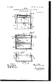
In the accompanying drawings, Figure 1 is a view in perspective of my improved cabinetwork for a sewing-machine table. Fig. 2 is a front side elevation of the right-hand end portion of the cabinet-work and shows the front of the drawer-case, which in the main forms the said end of the cabinet-Work. Fig. 3 is a front side elevation corresponding with Fig. 2 except that in Fig. 3 the drawer-case is removed. Fig. 4C is an inner side elevation of the said drawer-case. Fig. 5 is a vertical Section on line 5 5, Fig. 2, looking inwardly. Fig. 6 is a top plan in section on line 6 6, Fig. 5.
Referring to the drawings, A indicates the table-top of my improved cabinet-work. The table-top A extends over two drawer-cases B and B, arranged at opposite sides, respectively, of the cabinet-work and next below opposite ends, respectively, of the table-top. The drawer-cases B are arranged, therefore, a suitable distance apart longitudinally of the table-top A. A molding or upper front piece D bridges the space between the two drawercases B at the upper ends of the said cases and extends along the forward edge of the tabletop. The front (see Figs. 5 and 6) of the upper drawer I) of each drawer-case B is formed by a molding G, which corresponds with the molding D in width (see Figs. 1 and 2) and represents an extension of the said molding Dthat is, each drawer-front-forming molding G and the molding D are arranged in the same plane horizontally and correspond in I width. The drawer-front-representingmoldings G extend at their outer ends into contiguity or close proximity to moldings or side pieces K, which extend along the table-top at the outer sides of the upper drawers of the cases B. It will be observed, therefore, that my improved cabinet-work comprises moldings or side pieces K, extending forwardly and rearwardly along the side edges of the table-top A and representing rearward extensions of the drawer-front-representing moldings Gr.
Both ends of the cabinet-work and both drawer-cases correspond in construction, and a full illustration of one end of the cabinetwork, including one of the drawer-cases, is deemed to be sufficient. The molding or upper front piece D participates in the formation of the stationary framework of the cabinet between the two drawer-cases. The molding or side piece K at each end of the tabletop A participates in the formation of the drawer-case at the said end of the table-top and forms the outer side wall of the upper drawer compartment of the said drawercase. Notwithstanding the functions performed, as hereinbefore stated, by the moldings D, G, and K they all appear as participatingin the thickness of the table-top and not only confer the appearance of massiveness to the tabletop, but materially improve the appearance of the entire cabinet-work of the sewing-machine table.
A drawer-case is shown detached in Fig. 41, which, as already indicated, is an inner side view of the said case.
Each drawer-case (see Figs. 4, 5, and 6) comprises a top 10 and three shelves 12, arranged at suitable intervals vertically below the said top 10, and the top 10 and the shelves 152 participate in the formation of drawercompartments, with the upper drawer-compartment of the drawer-case formed between the top 10 and upper shelf 12, and the drawer b, which occupies the said compartment, is smaller vertically than the drawers 0 of the remaining compartments. The top 10 is removably attached to the table-top A by suitably-applied screws 8, as shown in Fig. 5. The said upper compartment has an outer side wall formed by a molding or side piece K, as already indicated, and also has a rear end wall L.
The top 10 and shelves 12 of each drawercase are suitably connected together by two upright wooden pieces P, arranged at the inner side of the case a suitable distance apart forwardly and rearwardly, and the top 10 and shelves 12 of thesaid case are glued or otherwise fastened to the said uprights. The forward upright P is located at the forward end of the drawer-case, and the drawer-front G of the upper drawer of the said case has its outer surface, as shown very clearly in Fig. 6, arranged flush at the inner end of the said front with the outer side of the molding D, and the said drawer-front at its outer end overlaps the forward end of the adjacent molding or side piece K, and the said upright is cut away, as at 13 (see also Fig. 4:) to accommodate the arrangement of the aforesaid molding G flush with the molding D.
At the outer side of each drawer-case, centrally between the ends of the case, (see Figs. 1, 4, and 6,) is arranged an upright piece Q, which engages recesses 14, formed in the shelves 11 and extends at its upper end into a mortise or hole 15, formed in the adjacent molding or side piece K at a point inwardly from the outer side of the said member K, and the said member K, the top 10,, and the shelves 12 of the said case are glued or otherwise attached to the said upright.
Each drawer-case is provided, preferably in the inner side of the forward of the inner uprights P of the said case, (see Figs. 1, 5. and 6,) with a groove 16, which extends from the upper end to the lower end of the case and is engaged by a correspondingly-arranged tongue 17, formed upon the stationary framework provided, as already indicated, between the two drawer-cases, which tongue is shown very clearly in Fig. 3.
By the construction hereinbefore described it will be observed that the outer upright Q of a drawer-case B extends into the molding or side piece K of the said drawer-case without being visible at the outer side of the said molding or side piece; that the upper end of the said drawer-case appears as participating in the formation of the table-top, and thereby materially adds to the attractiveness of the cabinet-work; that the said drawer-case is simple and inexpensive in construction, and that the tongue and groove connection formed between the drawer-case and the stationary framework at the inner side of the drawercase steadies the drawer-case.
What 1 claim is 1. Cabinet-work for a sewing-machine table, comprising a table-top; 'a suitably-supported drawer-case arranged next below one end of the table-top and comprising shelves arranged a suitable distance apart vertically below the table-top, with the compartment formed between the upper extremity of the drawer-case and the upper shelf smaller vertically than the remaining compartment or compartments of the drawer-case, said drawercase also comprising a side piece forming the outer side wall of the first-mentioned compartment and extending along the adjacent side edge of the table-top; the drawers in the drawer-compartments, with the upper drawer having a front which corresponds in width with the aforesaid side piece and extends inwardly along the forward edge of the tabletop from the forward end of the said side piece, and a front piece corresponding in width with the aforesaid drawer-front and extending along the forward edge of the tabletop from the inner end of the said drawerfront.
2. Cabinet-work for a sewing-machine table, comprising a table-top; a drawer-case arranged next below the table-top and comprising a top removably attached to the tabletop, shelves arranged a suitable distance apart vertically below the top of the drawer-case and a side piece forming the outer side wall of the compartment formed between the top of the drawer-case and the upper shelf, which side piece extends along the adjacent side edge of the table-top; the drawers in the drawercompartments, with the upper drawer having a front which corresponds in width with the aforesaid side piece and extends inwardly along the forward edge of the table-top from the forward end of the said side piece, and a front piece corresponding in width with the aforesaid drawer-front and extending along the forward edge of the table-top from the inner end of the said drawer-front.
3. Cabinet-work for a sewing-machine table, comprising a table-top; adrawer-case arranged next below one end of and attached to the table-top and comprising shelves arranged a suitable distance apart vertically below the table-top to form drawer-compartments, and a side piece which forms the outer side wall of the upper drawer-compartment and extends along the adjacent side edge of the table-top; the drawers in the drawer compartment, with the upper drawer having a front which corresponds in width with the aforesaid side piece and extends inwardly along the forward edge of the table-top from the forward end of the said side piece; stationary framework at the inner side of the drawer-case, and an upright tongue-and-groove connection between the d rawer-case and the said stationary framework.
4. Cabinet-work for a sewing-machine table comprising a table-top and a suitably-supported drawer-case arranged below and attached to the table-top and comprising the following: shelves arranged a suitable distance apart vertically; a side piece which forms the outer side wall of the drawer-compartment formed between the upper shelf and the upper extremity of the drawer-case and extends along the adjacent side edge of the table-top; uprights connecting together and suitably attached to the shelves of the drawer-case at the inner side of the case, and an upright arranged centrally between the ends of the drawer-case at the outer side of the case and connecting together and attached to the shelves of the said case and extending into and attached to the aforesaid side piece at a point inwardly from the outer side of the said side piece.
5. Cabinet-work for a sewing-machine table comprising a table-top, a drawer-case arranged next below the table-top and comprising the following: a top removably attached to the table-top, shelves arranged a suitable distance apart vertically below the top of the drawer-case with the compartment formed between the top of the drawercase and the upper shelf smaller vertically than the remaining compartment or compartments of the drawer-case, a side molding forming the outer side wall of the upper drawer-compartment and extending along the adjacent side edge of the table-top, uprights connecting together and suitably attached to the top and shelves of the drawer-case at the inner side of the case, and an upright arranged centrally between the ends of the drawer-case at the outer side of the case and connecting together and attached to the shelves of the said case and extending into and attached to the aforesaid side molding at a point inwardly from the outer side of the said molding.
6. Cabinet-work for a sewing-machine table, comprising a table-top; a drawer-compartment formed next below one end of the table-top; a side piece forming the outer side wall of the said compartment and extending along the adjacent side edge of the table-top;
the drawer in the said compartment, which drawer has a front which corresponds in width with the aforesaid side piece and extends inwardly along the forward edge of the tabletop from the forward end of the said side piece, and a front piece corresponding in width with the drawer-front and extending along the forward edge of the table-top from the inner end of the drawer-front.
7 Cabinet-work for a sewing-machine table, comprising a table-top; a drawer-compartment formed next below an end of the table-top; a side molding forming the outer side wall of the side edge of the table-top; the drawer in the said compartment, which drawer has a front formed by a molding which corresponds in width with the aforesaid side molding and extends inwardly along the forward edge of the table-top from and overlapping the forward end of the said side molding, and a molding corresponding in width with the aforesaid drawer front forming molding and extending along the forward edge of the table-top from theinner end of the said drawer-front-forming molding.
8. Cabinet-work for a sewing-machine table comprising a table-top; a drawer-compartment formed below an end of the tabletop; a side piece forming the outer side wall of the said drawer-compartment and extending along the adjacent side edge of the tabletop; the drawer in the said drawer-compartment, which drawer has a front which corresponds in width with the aforesaid side piece and extends inwardly along the forward edge of the table-top from and overlaps the forward end of the said side piece, and a front piece corresponding in width with the aforesaid drawer-front and extending along the forward edge of the table-top from the inner end of the said drawer-front and flush at its outer side with the outer side of the drawerfront.
9. Cabinet-work for a sewing-machine table comprising a table-top; shelves arranged a suitable distance apart vertically below an end of the table-top; a side piece forming the outer side wall of the drawer-compartment formed between the upper shelf and the tabletop and extending along the adjacent side edge of the table-top; the drawers in the drawer-compartments,with the upper drawer having a front which extends inwardly along the forward edge of the table-top from the forward end of the aforesaid side piece; uprights connecting together and suitably attached to the shelves at the inner side of the drawer-case comprising the said shelves and uprights; an upright arranged centrally between the rear and forward ends of the drawercase at the outer side of the case and connecting together and attached to the shelves and extending into and attached to the aforesaid IIO side piece at a point inwardly from the outer side of the said side piece; stationary framework at the inner side of the drawer-case; an upright tongue-and-groove connection between one of the inner uprights of the drawercase and the said stationary framework; a front piece corresponding in width with the aforesaid drawer-front and extending along the forward edge of the table-top from the inner end of the said drawer-front and means IO removably attaching the drawer-case to the table-top.
In testimony whereof I sign the foregoing specification in the presence of two witnesses.
THEODOR KUNDTZ. WVitnesses:
C. H. DoRER, B. 0. BROWN.
Priority Applications (1)
| Application Number | Priority Date | Filing Date | Title |
|---|---|---|---|
| US23178304A US782858A (en) | 1904-11-07 | 1904-11-07 | Cabinet-work for sewing-machine tables. |
Applications Claiming Priority (1)
| Application Number | Priority Date | Filing Date | Title |
|---|---|---|---|
| US23178304A US782858A (en) | 1904-11-07 | 1904-11-07 | Cabinet-work for sewing-machine tables. |
Publications (1)
| Publication Number | Publication Date |
|---|---|
| US782858A true US782858A (en) | 1905-02-21 |
Family
ID=2851344
Family Applications (1)
| Application Number | Title | Priority Date | Filing Date |
|---|---|---|---|
| US23178304A Expired - Lifetime US782858A (en) | 1904-11-07 | 1904-11-07 | Cabinet-work for sewing-machine tables. |
Country Status (1)
| Country | Link |
|---|---|
| US (1) | US782858A (en) |
-
1904
- 1904-11-07 US US23178304A patent/US782858A/en not_active Expired - Lifetime
Similar Documents
| Publication | Publication Date | Title |
|---|---|---|
| US3846002A (en) | Building unit for furniture | |
| US797826A (en) | Furniture. | |
| US782858A (en) | Cabinet-work for sewing-machine tables. | |
| US676157A (en) | Combined merchant's display and stock cabinet. | |
| US332360A (en) | Joseph penney | |
| US343041A (en) | littjle | |
| US809960A (en) | Cabinet-work for sewing-machine tables. | |
| US825695A (en) | Drawer-slide. | |
| US1073574A (en) | Desk. | |
| GB191318180A (en) | Improvements in Sectional Cabinets and the like. | |
| US868309A (en) | Locker construction. | |
| USD31650S (en) | Asskixoll of onk | |
| US697582A (en) | Drawer for sewing-machine stands or other articles of furniture. | |
| US1339501A (en) | Sewing-machine cabinet | |
| US133075A (en) | Improvement in sewing-machine tables | |
| US1254499A (en) | Domestic furniture. | |
| US528932A (en) | Combination article of furniture and collapsible table | |
| US852982A (en) | Display-case. | |
| US164087A (en) | Improvement in dressing-cases, or combined bureaus and wardrobes | |
| US127136A (en) | Improvement in swinging drawers for sewing-machine tables | |
| US509198A (en) | Knockdown furniture | |
| US135440A (en) | Improvement in cupboards and extension tables combined | |
| US902664A (en) | Wall-cabinet. | |
| USD18178S (en) | Design for a cabinet-desk | |
| US531939A (en) | Phillip hires |