US7809331B2 - Data communication apparatus - Google Patents
Data communication apparatus Download PDFInfo
- Publication number
- US7809331B2 US7809331B2 US11/719,598 US71959805A US7809331B2 US 7809331 B2 US7809331 B2 US 7809331B2 US 71959805 A US71959805 A US 71959805A US 7809331 B2 US7809331 B2 US 7809331B2
- Authority
- US
- United States
- Prior art keywords
- data communication
- communication device
- electrodes
- user
- housing
- Prior art date
- Legal status (The legal status is an assumption and is not a legal conclusion. Google has not performed a legal analysis and makes no representation as to the accuracy of the status listed.)
- Expired - Fee Related, expires
Links
Images


Classifications
-
- H—ELECTRICITY
- H04—ELECTRIC COMMUNICATION TECHNIQUE
- H04B—TRANSMISSION
- H04B13/00—Transmission systems characterised by the medium used for transmission, not provided for in groups H04B3/00 - H04B11/00
- H04B13/005—Transmission systems in which the medium consists of the human body
-
- H—ELECTRICITY
- H04—ELECTRIC COMMUNICATION TECHNIQUE
- H04M—TELEPHONIC COMMUNICATION
- H04M1/00—Substation equipment, e.g. for use by subscribers
- H04M1/26—Devices for calling a subscriber
- H04M1/27—Devices whereby a plurality of signals may be stored simultaneously
- H04M1/274—Devices whereby a plurality of signals may be stored simultaneously with provision for storing more than one subscriber number at a time, e.g. using toothed disc
- H04M1/2745—Devices whereby a plurality of signals may be stored simultaneously with provision for storing more than one subscriber number at a time, e.g. using toothed disc using static electronic memories, e.g. chips
- H04M1/2753—Devices whereby a plurality of signals may be stored simultaneously with provision for storing more than one subscriber number at a time, e.g. using toothed disc using static electronic memories, e.g. chips providing data content
- H04M1/2757—Devices whereby a plurality of signals may be stored simultaneously with provision for storing more than one subscriber number at a time, e.g. using toothed disc using static electronic memories, e.g. chips providing data content by data transmission, e.g. downloading
-
- H—ELECTRICITY
- H04—ELECTRIC COMMUNICATION TECHNIQUE
- H04M—TELEPHONIC COMMUNICATION
- H04M1/00—Substation equipment, e.g. for use by subscribers
- H04M1/72—Mobile telephones; Cordless telephones, i.e. devices for establishing wireless links to base stations without route selection
- H04M1/724—User interfaces specially adapted for cordless or mobile telephones
- H04M1/72403—User interfaces specially adapted for cordless or mobile telephones with means for local support of applications that increase the functionality
Definitions
- the present invention relates to a communication device that transmits or receives data to and from a communication party via a human body being in contact with the communication party.
- the data communication device generally includes a plurality of electrodes exposed to the outside to make contact with a portion of the human body and a data communication unit for data transmission or reception.
- the electrodes are formed on the rear surface of a wrist watch or on the inner surface of a ring so that the electrodes are naturally brought into contact with the human body in a secure manner in the case where the data communication device is held by or equipped on the user.
- a data communication device in which a data communication unit is incorporated into a wrist watch type package, and electrodes are arranged in the width direction of a band part of the wrist watch so as to be opposed to each other, thereby enabling users to make the most of the data communication device without needing to pay attention to the electrode arrangement (see Patent Document 1 for reference).
- the human body communication is applied to a handheld information terminal such as a cellular phone or a PDA
- a handheld information terminal such as a cellular phone or a PDA
- signals from the handheld information terminal are not securely transmitted to the human body and thus making communication unstable, thereby disabling the communication.
- Patent Document 1 JP-A-2003-134009
- Patent Document 2 JP-A-2004-064435
- the invention has been made in view of the above-mentioned circumstances, and its object is to provide a data communication device capable of providing a secure contact between electrodes and a human body without requiring user's attention when the data communication device held by the user is in the process of a human body communication, thereby enabling a stable data communication.
- the grooved portion having a height lower than that of the peripheral portion can be naturally held by the user. Therefore, a portion of the human body such as fingers can be brought into contact with the electrodes formed on the grooved portion in an easy and secure manner without requiring the user's attention, thereby enabling a stable data communication.
- the data communication device in accordance with the invention may be configured in such a manner that the electrodes are formed on the surface of concave portions formed on lateral portions of the housing of the data communication device.
- the concave portions formed on the lateral portions of the housing can be naturally held by the user. Therefore, a portion of the human body such as fingers can be brought into contact with the electrodes formed on the concave portions in an easy and secure manner without requiring the user's attention while taking advantage of increased contact area, thereby enabling a stable data communication.
- the data communication device in accordance with the invention may be configured in such a manner that the electrodes are formed to have a wave-like uneven surface.
- the data communication device when the data communication device is held by the user, the user's fingers can be naturally brought into contact with the electrodes while being fitted into the wave-like uneven surface of the electrode. Therefore, the data communication can be performed in a stable manner.
- the contact area can be further increased.
- the data communication device in accordance with the invention may be configured in such a manner that at least one of the electrodes is divided into a plurality of electrode fragments.
- the user's fingers holding the data communication device can be brought into contact with at least one electrode fragment. Therefore, the data communication can be performed in a stable manner.
- the data communication device in accordance with the invention may be configured in such a manner that at the electrodes are formed on corners of the housing of the data communication device.
- the data communication device in accordance with the invention may be configured in such a manner that the lateral portions of the housing of the data communication device are formed to have rounded corners and the electrodes are arranged along the rounded lateral portions of the housing.
- the electrodes are formed to cover at least a portion of the corners of the housing of the data communication device.
- the user's fingers can be brought into contact with the electrodes formed on the corners. Therefore, the data communication can be performed in a more stable manner.
- the data communication device in accordance with the invention may be configured as a cellular phone unit.
- a data communication device capable of providing a secure contact between electrodes and a human body without requiring user's attention when the data communication device held by the user is in the process of a human body communication, thereby enabling a stable data communication.
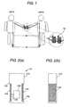
- FIG. 1 is a schematic diagram showing an exemplary configuration of a data communication system employing a data communication device related to embodiments of the invention.
- FIGS. 2A and 2B are schematic diagrams showing an exemplary configuration of a data communication device in accordance with a first embodiment, in which FIG. 2A is a front view thereof and FIG. 2B is a side view thereof.
- FIGS. 3A to 3C are schematic diagrams showing another exemplary configuration of a cellular phone in accordance with the first embodiment, in which FIG. 3A is a front view thereof, FIG. 3B is a side view thereof, and FIG. 3C is a rear view thereof.
- FIG. 4 is a schematic front view diagram showing another exemplary configuration of the data communication device in accordance with the first embodiment.
- FIGS. 5A to 5C are schematic diagrams showing another exemplary configuration of the data communication device in accordance with the first embodiment, in which FIG. 5A is a front view thereof, FIG. 5B is a side view thereof, and FIG. 5C is a rear view thereof.
- FIG. 6 is a schematic front view diagram showing an exemplary configuration of a data communication device in accordance with a second embodiment.
- FIG. 7 is a schematic diagram showing another exemplary configuration of the data communication device in accordance with the second embodiment.
- FIG. 8 is a schematic front view diagram showing an exemplary configuration of a cellular phone to which the data communication device related to the second embodiment is applied.
- FIG. 9 is a schematic diagram showing another exemplary configuration of the data communication device in accordance with the second embodiment.
- FIGS. 10A to 10C are schematic diagrams showing another exemplary configuration of the cellular phone in accordance with the second embodiment, in which FIG. 10A is a front view thereof, FIG. 10B is a side view thereof, and FIG. 10C is a rear view thereof.
- FIGS. 11A to 11C are schematic diagrams showing another exemplary configuration of the data communication device in accordance with the second embodiment, in which FIG. 11A is a front view thereof, FIG. 11B is a side view thereof, and FIG. 11C is a rear view thereof.
- FIG. 12 is a schematic diagram showing an exemplary configuration of a data communication system employing the cellular phone related to the second embodiment.
- FIG. 13 is a schematic front view diagram showing an exemplary arrangement of electrodes in a data communication device in accordance with a third embodiment.
- FIG. 14 is a schematic front view diagram showing an exemplary arrangement of electrodes in a data communication device in accordance with a third embodiment.
- FIG. 15 is a schematic front view diagram showing an exemplary arrangement of the electrodes in the data communication device in accordance with the third embodiment.
- FIG. 16 is a schematic front view diagram showing an exemplary arrangement of the electrodes in the data communication device in accordance with the third embodiment.
- FIG. 17 is a schematic front view diagram showing another exemplary arrangement of the electrodes in the data communication device in accordance with the third embodiment.
- FIGS. 18A to 18C are schematic diagrams showing another exemplary configuration of the cellular phone in accordance with the third embodiment, in which FIG. 18A is a front view thereof, FIG. 18B is a side view thereof, and FIG. 18C is a rear view thereof.
- a data communication device in accordance with embodiments of the invention is characterized in that the surfaces of electrodes are formed into a groove surface so that the surfaces of the electrodes have a height lower than that of other portions of housing, and thus making it easy to hold the data communication device without requiring user's attention.
- a cellular phone unit will be described as an example of a data communication device in which data is transmitted or received between two data communication devices held by respective users being in contact with each other via the users' body.
- FIG. 1 is a schematic diagram showing an exemplary configuration of a data communication system in which a human body communication is performed using a data communication device related to embodiments of the invention.
- the data communication system is configured to have a data communication device 10 held by a user A and a data communication device 10 held by a user B.
- a capacitive coupling between respective bodies of the users A and B forms a closed circuit.
- a bidirectional data communication can be performed between the data communication device 10 held by the user A and the data communication device 10 held by the user B.
- FIGS. 2A and 2B are schematic diagrams showing an exemplary configuration of a data communication device in accordance with a first embodiment of the invention, in which FIG. 2A is a front view thereof and FIG. 2B is a side view thereof.
- the first embodiment is characterized in that electrodes are formed on the surface of a concave formed on the lateral portion of the housing of the data communication device and the surfaces of the electrodes are formed into a groove surface so that the surfaces of the electrodes have a height lower than that of a peripheral portion thereof. As shown in the FIGS.
- the data communication device 10 is configured to have a transceiver electrode 103 and a reference electrode 104 formed respectively on the lateral portion of a housing 101 of the data communication device 10 , a data communication unit 105 accommodated in the housing 101 and having a function of transmitting and receiving data, and a lead line 106 for electrically connecting the transceiver electrode 103 and the reference electrode 104 to the data communication unit 105 .
- the transceiver electrode 103 and the reference electrode 104 are made of a conductive material.
- the transceiver electrode 103 and the reference electrode 104 are formed on concave portions 102 formed at positions where the user's fingers can be naturally brought into contact with the concave portions 102 when the data communication device 10 is held by one of the user's hands, such that the surfaces of the electrodes have a height slightly lower than those of the lateral portions of the housing 101 .
- the user's fingers can be brought into contact with the transceiver electrode 103 and the reference electrode 104 , thereby maintaining a secure contact with the human body and thus enabling a stable human body communication.
- the data communication unit 105 may include an oscillation unit for generating AC signals, a modem unit for modulating and demodulating the amplitude of transmission and reception data on the basis of the AC signals, a voltage application unit for applying modulated signals between the transceiver electrode 103 and the reference electrode 104 and transmitting data, a voltage detection unit for detecting a voltage applied between the transceiver electrode 103 and the reference electrode 104 and receiving data, and a transmission/reception mode switching unit for switching between a transmission mode and a reception mode.
- an oscillation unit for generating AC signals
- a modem unit for modulating and demodulating the amplitude of transmission and reception data on the basis of the AC signals
- a voltage application unit for applying modulated signals between the transceiver electrode 103 and the reference electrode 104 and transmitting data
- a voltage detection unit for detecting a voltage applied between the transceiver electrode 103 and the reference electrode 104 and receiving data
- a transmission/reception mode switching unit for switching between a transmission mode and
- FIGS. 3A to 3C each shows an exemplary configuration of a folder-type cellular phone to which the data communication device related to the present embodiment is applied.
- the transceiver electrode 113 and the reference electrode 114 are formed on the lateral portions of the housing 111 in a wave-like shape corresponding to the sectional shape of fingers.
- the housing 101 and 111 is made of an insulating material such as a resin similar to the case of a general handheld electronic apparatus.
- the surfaces of the transceiver electrode 103 and the reference electrode 104 of the data communication device 10 shown in FIGS. 2A to 2C may be covered, for example, with a resin coating (insulating material) 107 , as shown in FIG. 4 .
- the surfaces of the electrodes are covered with the insulating material, if the electrodes 103 and 104 are not brought into close contact with the human body, the human body communication may become unstable.
- the electrodes are formed on the surfaces of the concaves formed on the lateral portions of the housing 101 , the close-contactness between the electrodes and the human body can be improved.
- the data communication device 10 in such a manner as shown in FIGS. 3A to 3C that the transceiver electrode 113 and the reference electrode 114 are formed on the lateral portions of the housing 111 in a wave-like shape corresponding to the sectional shape of fingers, a high close-contactness can be advantageously provided between the human body and the electrodes without requiring the user's attention.
- the transceiver electrode 103 and the reference electrode 104 being in contact with the human body and transmitting data are formed on the surface of the concaves formed on the lateral portions of the housing 101 of the data communication device 10 . Therefore, when the data communication device 10 is held by the user, the electrodes 103 and 104 can be naturally brought into close contact with the user's fingers. Accordingly, the data communication based on the human body communication can be performed in a stable manner.
- the surfaces of the electrodes are formed into wave-like shapes, the user's fingers can be naturally fitted onto the electrodes. Therefore, it is possible to maintain a contact between the human body and the data communication device in a more secure manner.
- the occupying area of the electrodes on the surface of the housing can be reduced, and thus the data communication device can be made in a small size.
- FIGS. 5A to 5C each shows an exemplary configuration of a folder-type cellular phone to which the data communication device related to the present embodiment is applied.
- the transceiver electrode 113 and the reference electrode 114 are formed on the lateral portions of the housing 111 in a wave-like shape corresponding to the sectional shape of fingers.
- the user's fingers can be naturally fitted into grooved portions of the transceiver electrode 113 and the reference electrode 114 . Therefore, the contact with the human body can be maintained in a more secure manner.
- the transceiver electrode 113 and the reference electrode 114 being in contact with the human body and transmitting data are formed on the surface of the concaves formed on the lateral portions of the housing 111 of the data communication device 10 . Therefore, when the data communication device 10 is held by the user, the electrodes 103 and 104 can be naturally brought into close contact with the user's fingers. Accordingly, the data communication based on the human body communication can be performed in a stable manner.
- the surfaces of the electrodes are formed into wave-like shapes, the user's fingers can be naturally fitted onto the electrodes. Therefore, it is possible to maintain a contact between the human body and the data communication device in a more secure manner.
- the occupying area of the electrodes on the surface of the housing can be reduced, and thus the data communication device can be made in a small size.
- FIG. 6 is a schematic front view diagram showing an exemplary configuration of a data communication device in accordance with a second embodiment of the invention.
- the second embodiment is characterized in that a transceiver electrode 203 and a reference electrode 204 are divided into a plurality of electrode fragments.
- those elements corresponding to those described in relation to the first embodiment and shown in FIGS. 2A to 2C will be denoted by the same reference numerals.
- the data communication device 20 is configured to have the transceiver electrode 203 and the reference electrode 204 which are divided into a plurality of electrode fragments and formed at positions on the lateral portions of a housing 201 where the user's fingers can be naturally brought into contact with the electrodes 203 and 204 when the data communication device 20 is held by one of the user's hands.
- the respective electrode fragments of the transceiver electrode 203 and the reference electrode 204 are electrically connected to each other and connected via the lead line 106 to the data communication unit 105 accommodated in the housing 201 .
- the transceiver electrode 203 and the reference electrode 204 are formed on the surface of the concaves formed on the lateral portions of the housing 201 .
- the user's fingers When the data communication device 20 is held by one of the user's hands, the user's fingers can be brought into contact with at least one of the respective divided electrode fragments of the transceiver electrode 203 and the reference electrode 204 . Therefore, the contact between the human body and the data communication device 20 can be securely maintained by the user's fingers, thereby enabling a stable communication.
- the transceiver electrode 203 and the reference electrode 204 being in contact with the human body and transmitting data are formed on the surface of the concaves formed on the lateral portions of the housing 201 of the data communication device 20 . Therefore, when the data communication device 20 is held by the user, the electrodes 203 and 204 can be naturally brought into close contact with the user's fingers. Accordingly, the data communication based on the human body communication can be performed in a stable manner.
- FIG. 7 is a schematic front view diagram showing an exemplary configuration of a data communication device in accordance with a modified example of the data communication device shown in FIG. 6 .
- those elements corresponding to those described in relation to the first embodiment and shown in FIG. 6 will be denoted by the same reference numerals.
- the data communication device 20 is configured to have the transceiver electrode 203 and the reference electrode 204 which are divided into a plurality of electrode fragments and formed at positions on the lateral portions of a housing 201 where the user's fingers can be naturally brought into contact with the electrodes 203 and 204 when the data communication device 20 is held by one of the user's hands.
- the modified example is different from the first embodiment in that the respective electrode fragments of the transceiver electrode 203 and the reference electrode 204 are formed on the same surface of the housing, and other configurations are the same as those of the data communication device of the first embodiment. That is, The respective electrode fragments of the transceiver electrode 203 and the reference electrode 204 are electrically connected to each other and connected via the lead line 106 to the data communication unit 105 accommodated in the housing 201 .
- the user's fingers when the data communication device 20 is held by one of the user's hands, the user's fingers can be brought into contact with at least one of the respective divided electrode fragments of the transceiver electrode 203 and the reference electrode 204 . Therefore, the contact between the human body and the data communication device 20 can be securely maintained by the user's fingers, thereby enabling a stable communication.
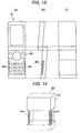
- FIG. 8 is a schematic front view diagram showing an exemplary configuration of a cellular phone to which the data communication device in accordance with the present embodiment is applied.
- a cellular phone 30 is configured in such a manner that a transceiver electrode 303 divided into two parts is formed on the lower portions of the lateral portions of a housing 301 at positions where the user's fingers can be naturally brought into contact with the transceiver electrode 303 when the cellular phone 30 is held by one of the user's hands, and a reference electrode 304 is formed, for example, on the upper portion of the rear surface of the housing 301 so that the user does not touch the reference electrode.
- the transceiver electrode 303 is formed on the surfaces of the concaves formed on the lateral portions of the housing 301 .
- the data communication can be performed in a stable manner.
- the electrode arrangement in the cellular phone 30 is not limited to this, but the transceiver electrode 303 and the reference electrode 304 may be formed at positions where the cellular phone 30 can be held by one of the user's hands, in a similar manner to the case of the data communication device 20 shown in FIGS. 5A to 5C .
- the positional relationship shown in FIG. 8 between the transceiver electrode 303 and the reference electrode 304 may be changed in such an opposite manner that the transceiver electrode 303 is formed on the rear surface of the housing 301 while forming the reference electrode 304 on the lateral portions of the housing 301 so as to be divided into two parts.
- FIG. 9 is a schematic front view diagram showing an exemplary configuration of a cellular phone to which the data communication device in accordance with a modified example of the present embodiment is applied.
- the configuration shown in FIG. 9 is different from that shown in FIG. 8 in that respective electrode fragments of the transceiver electrode 203 and the reference electrode 204 are formed on the same surface as the surface of the housing, and other configurations are the same as those of shown in FIG. 8 .
- a cellular phone 30 is configured in such a manner that a transceiver electrode 303 divided into two parts is formed on the lower portions of the lateral portions of a housing 301 at positions where the user's fingers can be naturally brought into contact with the transceiver electrode 303 when the cellular phone 30 is held by one of the user's hands, and a reference electrode 304 is formed, for example, on the upper portion of the rear surface of the housing 301 so that the user does not touch the reference electrode.
- the data communication can be performed in a stable manner.
- FIGS. 10A to 10C are schematic diagrams showing an exemplary configuration of a cellular phone to which the data communication device in accordance with the present embodiment is applied, in which FIG. 10A is a front view thereof, FIG. 10B is a side view thereof, and FIG. 10C is a rear view thereof.
- the transceiver electrode 303 divided into two parts is formed on the lateral portions of the housing 301 at positions where the user's fingers can be naturally brought into contact with the transceiver electrode 303 when the cellular phone is held by one of the user's hands, and the reference electrode 304 is formed on the lower portion of the rear surface of the housing 301 .
- the reference electrode 305 may be formed, for example, on the upper portion of the rear surface of the housing 301 so that the user does not touch the reference electrode 305 .
- the transceiver electrode 303 and the reference electrode 304 are formed on the surfaces of the concaves formed on the lateral portions of the housing 301 .
- the user's body can be brought into contact with substantially the entire electrodes in a secure manner when the cellular phone 30 is held by one of the user's hands.
- an electrode 306 on a hinge portion of the folder-type cellular phone or configuring at least one of operation keys to act as an electrode, the unpleasant appearance of the data communication device can be eliminated.
- a portion of the electrode fragments may be formed on the top surface of the housing.
- FIGS. 11A to 11C are schematic diagrams showing an exemplary configuration of a cellular phone to which the data communication device in accordance with the present embodiment is applied, in which FIG. 11A is a front view thereof, FIG. 11B is a side view thereof, and FIG. 11C is a rear view thereof.
- the configuration shown in FIGS. 11A to 11C is different from that shown in FIGS. 10 A to 10 C in that respective electrode fragments of the transceiver electrode 303 and the reference electrode 304 are formed on the same surface as the surface of the housing, and other configurations are the same as those of shown in FIGS. 10A to 10C .
- the transceiver electrode 303 divided into two parts is formed on the lateral portions of the housing 301 at positions where the user's fingers can be naturally brought into contact with the transceiver electrode 303 when the cellular phone is held by one of the user's hands, and the reference electrode 304 is formed on the lower portion of the rear surface of the housing 301 .
- the reference electrode 305 may be formed, for example, on the upper portion of the rear surface of the housing 301 so that the user does not touch the reference electrode 305 . In this way, by forming the electrodes on three different locations on the cellular phone 30 , the user's body can be brought into contact with substantially the entire electrodes in a secure manner when the cellular phone 30 is held by one of the user's hands.
- an electrode 306 on a hinge portion of the folder-type cellular phone or configuring at least one of operation keys to act as an electrode, the unpleasant appearance of the data communication device can be eliminated.
- a portion of the electrode fragments may be formed on the top surface of the housing.
- FIG. 12 is a schematic diagram showing an exemplary configuration of a data communication system in which a data communication is performed between respective cellular phones 30 held by users A and B.
- the users A and B are holding the respective cellular phones 30 in each other's hand while being in contact with the transceiver electrode 303 divided into parts and formed on the lower portions of the lateral portions of the housing 301 .
- the bodies of the users A and B connected via their hands being in contact with each other act as a transmission line 307 in the data communication, and an electrostatic coupling between the reference electrodes 304 being in non-contact with the users' hands forms a reference line 308 .
- a closed circuit is formed between two cellular phones 30 via the human body, thereby enabling a bidirectional data communication between the cellular phones.
- the transceiver electrode 203 and the reference electrode 204 being in contact with the human body and transmitting data are divided into a plurality of electrode fragments and formed on the lateral portions of the housing 201 .
- the transceiver electrode 303 is divided into two parts and formed on the lower portion of the lateral portions of the housing 301 , and the reference electrode 304 is formed on the lower portion of the rear surface of the housing 301 .
- the cellular phones 30 having such a configuration are held in two users' respective hands while bringing the other hands of the users into contact with each other, a data communication based on the human body communication can be performed between the cellular phones 30 in a stable manner.
- FIGS. 13A to 13C are schematic diagrams showing an exemplary configuration of a cellular phone to which a data communication device related to a third embodiment of the invention is applied, in which FIG. 13A is a front view thereof, FIG. 13B is a side view thereof, and FIG. 13C is a rear view thereof.
- electrodes are formed on the corners of the housing of the data communication device, and the user's fingers can be brought into contact with the electrodes formed on the corners in a secure manner. Accordingly, a data communication can be performed in a stable manner.
- basic components are the same as those of in the first and second embodiments, and thus descriptions thereof will be omitted.
- the data communication device 40 is configured to have a transceiver electrode 403 and a reference electrode 404 which are formed on corners 402 of the lateral portions of the housing 401 so that the user's fingers are naturally brought into contact with the corners 402 when the user is supporting the housing 401 to operate the data communication device 40 with one of the user's hands.
- the transceiver electrode 403 and the reference electrode 404 are formed on the surfaces of the concaves formed on the lateral portions of the housing 401 .
- the user's fingers When the data communication device 40 is held by one of the user's hands, the user's fingers can be brought into contact with the transceiver electrode 403 and the reference electrode 404 . Therefore, the contact between the human body and the data communication device 40 can be securely maintained by the user's fingers, thereby enabling a stable communication.
- a portion or the entire portions of the corners of the lateral surface of the housing of the data communication device 40 may be obliquely cut away to form a concave 402 in the corners so that the transceiver electrode 403 and the reference electrode 404 are formed on the surface of the concave 402 .
- the corners of the lateral surface of the housing of the data communication device 40 may be rounded while forming a concave 402 in the corners so that the transceiver electrode 403 and the reference electrode 404 are formed on the surface of the concave 402 .
- the curvature of the corners may be designed to have a sufficiently small gap between the user's fingers and the data communication device 40 when the user is supporting the data communication device 40 .
- the user's fingers can be brought into contact with the transceiver electrode 403 and the reference electrode 404 . Therefore, the contact between the human body and the data communication device 40 can be securely maintained by the user's fingers, thereby enabling a stable communication.
- FIG. 17 shows a modified example of the data communication device shown in FIG. 16 .
- the configuration shown in FIG. 17 is different from that shown in FIG. 16 in that respective electrode fragments of the transceiver electrode 403 and the reference electrode 404 are formed on the same surface as the surface of the housing, and other configurations are the same as those of shown in FIG. 16 . That is, the corners of the lateral surface of the housing of the data communication device 40 may be rounded so that the transceiver electrode 403 and the reference electrode 404 are formed on the surface of the concave 402 . The curvature of the corners may be designed to have an appropriate gap between the user's fingers and the data communication device 40 when the user is supporting the data communication device 40 .
- the user's fingers can be brought into contact with the transceiver electrode 403 and the reference electrode 404 . Therefore, the contact between the human body and the data communication device 40 can be securely maintained by the user's fingers, thereby enabling a stable communication.
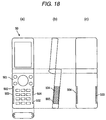
- FIGS. 18A to 18C are schematic diagrams showing an exemplary configuration of a folder-type cellular phone to which the data communication device in accordance with the third embodiment of the invention is applied, in which FIG. 18A is a front view thereof, FIG. 18B is a side view thereof, and FIG. 18C is a rear view thereof.
- the data communication device 50 is configured in such a manner that corners 502 on the lateral portions of the housing 501 of the data communication device 50 is rounded to have a curvature designed to have a sufficiently small gap between the user's fingers and the data communication device 50 when the user is supporting the data communication device 50 so that the user's fingers are naturally brought into contact with the corners 502 when the user is supporting the housing 501 to operate the data communication device 50 with one of the user's hands, thereby forming a transceiver electrode 503 and a reference electrode 504 on the rounded surface of corners 502 .
- the user's fingers can be brought into contact with the transceiver electrode 503 and the reference electrode 504 . Therefore, the contact between the human body and the data communication device 50 can be securely maintained by the user's fingers, thereby enabling a stable communication.
- the user's fingers can be brought into contact with the transceiver electrode 503 and the reference electrode 504 . Therefore, the contact between the human body and the data communication device 50 can be securely maintained by the user's fingers, thereby enabling a stable communication.
- the invention is not limited to this.
- the invention may be applied to a handheld music player or a handheld terminal unit such as a PDA.
- the invention is advantageous in that it provides a data communication device capable of providing a secure contact between electrodes and a human body without requiring user's attention when the data communication device held by the user is in the process of a human body communication, thereby enabling stable data communication. Therefore, the invention can be advantageously applied to a handheld terminal unit such as a cellular phone for data communication.
Landscapes
- Engineering & Computer Science (AREA)
- Computer Networks & Wireless Communication (AREA)
- Signal Processing (AREA)
- Telephone Set Structure (AREA)
Applications Claiming Priority (7)
| Application Number | Priority Date | Filing Date | Title |
|---|---|---|---|
| JP2004336083 | 2004-11-19 | ||
| JP2004-336083 | 2004-11-19 | ||
| JP2004335518 | 2004-11-19 | ||
| JP2004-335518 | 2004-11-19 | ||
| JP2004-335519 | 2004-11-19 | ||
| JP2004335519 | 2004-11-19 | ||
| PCT/JP2005/021267 WO2006054706A1 (ja) | 2004-11-19 | 2005-11-18 | データ通信装置 |
Publications (2)
| Publication Number | Publication Date |
|---|---|
| US20090149212A1 US20090149212A1 (en) | 2009-06-11 |
| US7809331B2 true US7809331B2 (en) | 2010-10-05 |
Family
ID=36407242
Family Applications (1)
| Application Number | Title | Priority Date | Filing Date |
|---|---|---|---|
| US11/719,598 Expired - Fee Related US7809331B2 (en) | 2004-11-19 | 2005-11-18 | Data communication apparatus |
Country Status (4)
| Country | Link |
|---|---|
| US (1) | US7809331B2 (ja) |
| JP (1) | JP4567006B2 (ja) |
| CN (1) | CN101057427B (ja) |
| WO (1) | WO2006054706A1 (ja) |
Cited By (4)
| Publication number | Priority date | Publication date | Assignee | Title |
|---|---|---|---|---|
| US20100231353A1 (en) * | 2007-02-14 | 2010-09-16 | Kaba Ag | System and portable device for transmitting identification signals |
| US20100321159A1 (en) * | 2009-06-18 | 2010-12-23 | Authentec, Inc. | Touch based data communication using biometric finger sensor and associated methods |
| US20120262005A1 (en) * | 2006-03-21 | 2012-10-18 | Murata Manufacturing Co., Ltd. | Device for transporting energy by partial influence through a dielectric medium |
| US10715189B2 (en) | 2016-03-09 | 2020-07-14 | Kyocera Corporation | Electronic device |
Families Citing this family (16)
| Publication number | Priority date | Publication date | Assignee | Title |
|---|---|---|---|---|
| CN102047589A (zh) * | 2007-10-11 | 2011-05-04 | 阿尔卑斯电气株式会社 | 信息终端装置 |
| JP4717141B2 (ja) * | 2007-12-26 | 2011-07-06 | アルプス電気株式会社 | 携帯機器 |
| JP2009302863A (ja) * | 2008-06-12 | 2009-12-24 | Nippon Telegr & Teleph Corp <Ntt> | 携帯電話機 |
| JP4838287B2 (ja) * | 2008-09-03 | 2011-12-14 | 日本電信電話株式会社 | トランシーバ |
| JP2010062818A (ja) * | 2008-09-03 | 2010-03-18 | Nippon Telegr & Teleph Corp <Ntt> | 電極 |
| JP2010062845A (ja) * | 2008-09-03 | 2010-03-18 | Nippon Telegr & Teleph Corp <Ntt> | トランシーバ |
| JP5141653B2 (ja) * | 2009-08-28 | 2013-02-13 | 株式会社デンソー | 防犯用警報装置 |
| JP2012064996A (ja) * | 2010-09-14 | 2012-03-29 | Ntt Electornics Corp | 電界通信装置 |
| JP5066283B2 (ja) * | 2011-08-05 | 2012-11-07 | 日本電信電話株式会社 | 携帯電話機 |
| CN103049151B (zh) * | 2011-10-14 | 2017-12-12 | 禾瑞亚科技股份有限公司 | 触摸屏的侦测装置与方法 |
| JP6238351B2 (ja) * | 2013-12-12 | 2017-11-29 | パナソニック株式会社 | 人体通信装置 |
| US20150199047A1 (en) * | 2014-01-15 | 2015-07-16 | Mediatek Inc. | Touch panel devices, electronic devices, and virtual input methods thereof |
| US9641261B2 (en) | 2014-05-09 | 2017-05-02 | Sony Corporation | Wearable wireless electronic devices and methods of providing communications via wearable wireless electronic devices |
| US9485034B2 (en) * | 2014-08-06 | 2016-11-01 | Sony Corporation | Device with external metal frame as coupling element for body-coupled-communication signals |
| JP6914134B2 (ja) * | 2017-07-25 | 2021-08-04 | アドソル日進株式会社 | データ通信用電極、データ通信装置及びデータ通信システム |
| US11115074B1 (en) * | 2018-07-05 | 2021-09-07 | Snap Inc. | Wearable device antenna |
Citations (6)
| Publication number | Priority date | Publication date | Assignee | Title |
|---|---|---|---|---|
| JP2001308803A (ja) | 2000-04-26 | 2001-11-02 | Matsushita Electric Works Ltd | データ通信システム及びそのシステムを利用した機器のセキュリティシステム及び、データ通信システム又はセキュリティシステムを利用した携帯電話及び携帯情報端末 |
| JP2002246987A (ja) | 2001-02-22 | 2002-08-30 | Matsushita Electric Works Ltd | データ通信システム及びデータ通信装置 |
| JP2003134009A (ja) | 2001-10-25 | 2003-05-09 | Matsushita Electric Works Ltd | データ通信装置 |
| JP2004064435A (ja) | 2002-07-29 | 2004-02-26 | Tokai Rika Co Ltd | 携帯機 |
| JP2004128606A (ja) | 2002-09-30 | 2004-04-22 | Nippon Telegr & Teleph Corp <Ntt> | データ通信装置およびデータ通信装置収納用かばん |
| US20040196257A1 (en) * | 2003-04-07 | 2004-10-07 | Alps Electric Co., Ltd. | Rotary input device |
Family Cites Families (1)
| Publication number | Priority date | Publication date | Assignee | Title |
|---|---|---|---|---|
| CN2426250Y (zh) * | 2000-05-12 | 2001-04-04 | 李山宾 | 手持式电话 |
-
2005
- 2005-11-18 CN CN2005800391112A patent/CN101057427B/zh not_active Expired - Fee Related
- 2005-11-18 WO PCT/JP2005/021267 patent/WO2006054706A1/ja not_active Ceased
- 2005-11-18 US US11/719,598 patent/US7809331B2/en not_active Expired - Fee Related
- 2005-11-18 JP JP2006545172A patent/JP4567006B2/ja not_active Expired - Fee Related
Patent Citations (6)
| Publication number | Priority date | Publication date | Assignee | Title |
|---|---|---|---|---|
| JP2001308803A (ja) | 2000-04-26 | 2001-11-02 | Matsushita Electric Works Ltd | データ通信システム及びそのシステムを利用した機器のセキュリティシステム及び、データ通信システム又はセキュリティシステムを利用した携帯電話及び携帯情報端末 |
| JP2002246987A (ja) | 2001-02-22 | 2002-08-30 | Matsushita Electric Works Ltd | データ通信システム及びデータ通信装置 |
| JP2003134009A (ja) | 2001-10-25 | 2003-05-09 | Matsushita Electric Works Ltd | データ通信装置 |
| JP2004064435A (ja) | 2002-07-29 | 2004-02-26 | Tokai Rika Co Ltd | 携帯機 |
| JP2004128606A (ja) | 2002-09-30 | 2004-04-22 | Nippon Telegr & Teleph Corp <Ntt> | データ通信装置およびデータ通信装置収納用かばん |
| US20040196257A1 (en) * | 2003-04-07 | 2004-10-07 | Alps Electric Co., Ltd. | Rotary input device |
Non-Patent Citations (1)
| Title |
|---|
| International Search Report (PCT/JP2005/021267) dated Jan. 31, 2006. |
Cited By (8)
| Publication number | Priority date | Publication date | Assignee | Title |
|---|---|---|---|---|
| US20120262005A1 (en) * | 2006-03-21 | 2012-10-18 | Murata Manufacturing Co., Ltd. | Device for transporting energy by partial influence through a dielectric medium |
| US20120267963A1 (en) * | 2006-03-21 | 2012-10-25 | Murata Manufacturing Co., Ltd. | Device for transporting energy by partial influence through a dielectric medium |
| US8587156B2 (en) | 2006-03-21 | 2013-11-19 | Murata Manufacturing Co., Ltd. | Device for transporting energy by partial influence through a dielectric medium |
| US8587157B2 (en) * | 2006-03-21 | 2013-11-19 | Murata Manufacturing Co., Ltd. | Device for transporting energy by partial influence through a dielectric medium |
| US8729738B2 (en) * | 2006-03-21 | 2014-05-20 | Murata Manufacturing Co., Ltd. | Device for transporting energy by partial influence through a dielectric medium |
| US20100231353A1 (en) * | 2007-02-14 | 2010-09-16 | Kaba Ag | System and portable device for transmitting identification signals |
| US20100321159A1 (en) * | 2009-06-18 | 2010-12-23 | Authentec, Inc. | Touch based data communication using biometric finger sensor and associated methods |
| US10715189B2 (en) | 2016-03-09 | 2020-07-14 | Kyocera Corporation | Electronic device |
Also Published As
| Publication number | Publication date |
|---|---|
| JP4567006B2 (ja) | 2010-10-20 |
| US20090149212A1 (en) | 2009-06-11 |
| WO2006054706A1 (ja) | 2006-05-26 |
| CN101057427B (zh) | 2010-12-08 |
| JPWO2006054706A1 (ja) | 2008-06-05 |
| CN101057427A (zh) | 2007-10-17 |
Similar Documents
| Publication | Publication Date | Title |
|---|---|---|
| US7809331B2 (en) | Data communication apparatus | |
| EP3167559B1 (en) | Methods of providing body area network communications when a user touches a button of a wireless electronic device, and related wireless electronic devices and wearable wireless electronic devices | |
| US8050716B2 (en) | Mobile terminal | |
| EP2169924B1 (en) | Mobile wireless communications device having touch activated near field communications (NFC) circuit | |
| US9571612B2 (en) | Wrist phone with improved voice quality | |
| US8301212B2 (en) | Portable wireless apparatus and antenna structure | |
| US20110267238A1 (en) | Portable electronic device | |
| CN106785436A (zh) | 导电盖体、壳体组件和终端 | |
| US8803743B2 (en) | Portable electronic device | |
| CN206332181U (zh) | 导电盖体、壳体组件和终端 | |
| US8791870B2 (en) | Portable electronic device | |
| CN206557552U (zh) | 高稳定性的nfc智能手表 | |
| US8866694B2 (en) | Portable terminal | |
| KR200310610Y1 (ko) | 손목착용형 착신신호 전기자극형 이동통신장치 | |
| US20070108030A1 (en) | Handheld electronic communication device with metallic keypad | |
| JP4805218B2 (ja) | 携帯端末装置 | |
| JP4818973B2 (ja) | 携帯端末装置 | |
| KR20030088631A (ko) | 안테나 내장형 이동통신 단말기 | |
| JP4616379B2 (ja) | 携帯電話機 | |
| CN118053179A (zh) | 电子设备及其侧边指纹模组 | |
| JP2002033806A (ja) | 携帯無線装置 | |
| HK1236681A (en) | Conductive cover, housing assembly and terminal | |
| HK1236681A1 (en) | Conductive cover, housing assembly and terminal | |
| KR20060016023A (ko) | 전자기기의 스타일러스 펜 | |
| KR19990033449U (ko) | 플립형 휴대폰 |
Legal Events
| Date | Code | Title | Description |
|---|---|---|---|
| AS | Assignment |
Owner name: MATSUSHITA ELECTRIC INDUSTRIAL CO., LTD., JAPAN Free format text: ASSIGNMENT OF ASSIGNORS INTEREST;ASSIGNOR:KANO, HIDEKAZU;REEL/FRAME:020073/0444 Effective date: 20070423 |
|
| AS | Assignment |
Owner name: PANASONIC CORPORATION,JAPAN Free format text: CHANGE OF NAME;ASSIGNOR:MATSUSHITA ELECTRIC INDUSTRIAL CO., LTD.;REEL/FRAME:021818/0725 Effective date: 20081001 Owner name: PANASONIC CORPORATION, JAPAN Free format text: CHANGE OF NAME;ASSIGNOR:MATSUSHITA ELECTRIC INDUSTRIAL CO., LTD.;REEL/FRAME:021818/0725 Effective date: 20081001 |
|
| FEPP | Fee payment procedure |
Free format text: PAYOR NUMBER ASSIGNED (ORIGINAL EVENT CODE: ASPN); ENTITY STATUS OF PATENT OWNER: LARGE ENTITY |
|
| FPAY | Fee payment |
Year of fee payment: 4 |
|
| FEPP | Fee payment procedure |
Free format text: MAINTENANCE FEE REMINDER MAILED (ORIGINAL EVENT CODE: REM.) |
|
| LAPS | Lapse for failure to pay maintenance fees |
Free format text: PATENT EXPIRED FOR FAILURE TO PAY MAINTENANCE FEES (ORIGINAL EVENT CODE: EXP.); ENTITY STATUS OF PATENT OWNER: LARGE ENTITY |
|
| STCH | Information on status: patent discontinuation |
Free format text: PATENT EXPIRED DUE TO NONPAYMENT OF MAINTENANCE FEES UNDER 37 CFR 1.362 |
|
| FP | Lapsed due to failure to pay maintenance fee |
Effective date: 20181005 |