US7761887B2 - Recording medium having a reflector to prevent traveling of beam to recording layer - Google Patents
Recording medium having a reflector to prevent traveling of beam to recording layer Download PDFInfo
- Publication number
- US7761887B2 US7761887B2 US10/170,543 US17054302A US7761887B2 US 7761887 B2 US7761887 B2 US 7761887B2 US 17054302 A US17054302 A US 17054302A US 7761887 B2 US7761887 B2 US 7761887B2
- Authority
- US
- United States
- Prior art keywords
- disk
- recording medium
- recording
- optical pickup
- recording layer
- Prior art date
- Legal status (The legal status is an assumption and is not a legal conclusion. Google has not performed a legal analysis and makes no representation as to the accuracy of the status listed.)
- Expired - Fee Related, expires
Links
- 230000003287 optical effect Effects 0.000 claims abstract description 22
- 239000010409 thin film Substances 0.000 abstract 1
- 239000010410 layer Substances 0.000 description 24
- 238000000034 method Methods 0.000 description 11
- 239000000758 substrate Substances 0.000 description 6
- XAGFODPZIPBFFR-UHFFFAOYSA-N aluminium Chemical compound [Al] XAGFODPZIPBFFR-UHFFFAOYSA-N 0.000 description 4
- 229910052782 aluminium Inorganic materials 0.000 description 3
- 238000004519 manufacturing process Methods 0.000 description 3
- 229910052751 metal Inorganic materials 0.000 description 3
- 239000002184 metal Substances 0.000 description 3
- 239000000463 material Substances 0.000 description 2
- 230000000903 blocking effect Effects 0.000 description 1
- 239000012141 concentrate Substances 0.000 description 1
- 239000011521 glass Substances 0.000 description 1
- 238000001746 injection moulding Methods 0.000 description 1
- 229910021645 metal ion Inorganic materials 0.000 description 1
- 238000012544 monitoring process Methods 0.000 description 1
- 229920005668 polycarbonate resin Polymers 0.000 description 1
- 239000004431 polycarbonate resin Substances 0.000 description 1
- 239000011241 protective layer Substances 0.000 description 1
- 238000004528 spin coating Methods 0.000 description 1
- 238000004544 sputter deposition Methods 0.000 description 1
Images


Classifications
-
- G—PHYSICS
- G11—INFORMATION STORAGE
- G11B—INFORMATION STORAGE BASED ON RELATIVE MOVEMENT BETWEEN RECORD CARRIER AND TRANSDUCER
- G11B7/00—Recording or reproducing by optical means, e.g. recording using a thermal beam of optical radiation by modifying optical properties or the physical structure, reproducing using an optical beam at lower power by sensing optical properties; Record carriers therefor
- G11B7/24—Record carriers characterised by shape, structure or physical properties, or by the selection of the material
- G11B7/2403—Layers; Shape, structure or physical properties thereof
- G11B7/24062—Reflective layers
-
- G—PHYSICS
- G11—INFORMATION STORAGE
- G11B—INFORMATION STORAGE BASED ON RELATIVE MOVEMENT BETWEEN RECORD CARRIER AND TRANSDUCER
- G11B23/00—Record carriers not specific to the method of recording or reproducing; Accessories, e.g. containers, specially adapted for co-operation with the recording or reproducing apparatus ; Intermediate mediums; Apparatus or processes specially adapted for their manufacture
- G11B23/0014—Record carriers not specific to the method of recording or reproducing; Accessories, e.g. containers, specially adapted for co-operation with the recording or reproducing apparatus ; Intermediate mediums; Apparatus or processes specially adapted for their manufacture record carriers not specifically of filamentary or web form
- G11B23/0021—Record carriers not specific to the method of recording or reproducing; Accessories, e.g. containers, specially adapted for co-operation with the recording or reproducing apparatus ; Intermediate mediums; Apparatus or processes specially adapted for their manufacture record carriers not specifically of filamentary or web form discs
-
- G—PHYSICS
- G11—INFORMATION STORAGE
- G11B—INFORMATION STORAGE BASED ON RELATIVE MOVEMENT BETWEEN RECORD CARRIER AND TRANSDUCER
- G11B23/00—Record carriers not specific to the method of recording or reproducing; Accessories, e.g. containers, specially adapted for co-operation with the recording or reproducing apparatus ; Intermediate mediums; Apparatus or processes specially adapted for their manufacture
- G11B23/38—Visual features other than those contained in record tracks or represented by sprocket holes the visual signals being auxiliary signals
- G11B23/40—Identifying or analogous means applied to or incorporated in the record carrier and not intended for visual display simultaneously with the playing-back of the record carrier, e.g. label, leader, photograph
-
- G—PHYSICS
- G11—INFORMATION STORAGE
- G11B—INFORMATION STORAGE BASED ON RELATIVE MOVEMENT BETWEEN RECORD CARRIER AND TRANSDUCER
- G11B7/00—Recording or reproducing by optical means, e.g. recording using a thermal beam of optical radiation by modifying optical properties or the physical structure, reproducing using an optical beam at lower power by sensing optical properties; Record carriers therefor
- G11B7/08—Disposition or mounting of heads or light sources relatively to record carriers
- G11B7/085—Disposition or mounting of heads or light sources relatively to record carriers with provision for moving the light beam into, or out of, its operative position or across tracks, otherwise than during the transducing operation, e.g. for adjustment or preliminary positioning or track change or selection
- G11B7/08505—Methods for track change, selection or preliminary positioning by moving the head
- G11B7/08511—Methods for track change, selection or preliminary positioning by moving the head with focus pull-in only
-
- G—PHYSICS
- G11—INFORMATION STORAGE
- G11B—INFORMATION STORAGE BASED ON RELATIVE MOVEMENT BETWEEN RECORD CARRIER AND TRANSDUCER
- G11B7/00—Recording or reproducing by optical means, e.g. recording using a thermal beam of optical radiation by modifying optical properties or the physical structure, reproducing using an optical beam at lower power by sensing optical properties; Record carriers therefor
- G11B7/12—Heads, e.g. forming of the optical beam spot or modulation of the optical beam
- G11B7/121—Protecting the head, e.g. against dust or impact with the record carrier
-
- G—PHYSICS
- G11—INFORMATION STORAGE
- G11B—INFORMATION STORAGE BASED ON RELATIVE MOVEMENT BETWEEN RECORD CARRIER AND TRANSDUCER
- G11B7/00—Recording or reproducing by optical means, e.g. recording using a thermal beam of optical radiation by modifying optical properties or the physical structure, reproducing using an optical beam at lower power by sensing optical properties; Record carriers therefor
- G11B7/24—Record carriers characterised by shape, structure or physical properties, or by the selection of the material
- G11B7/2403—Layers; Shape, structure or physical properties thereof
- G11B7/24053—Protective topcoat layers lying opposite to the light entrance side, e.g. layers for preventing electrostatic charging
Definitions
- the present invention relates to a high-density disk structure preventing collision of an optical pickup's objective lens with a high-density disk which is placed upside down in a disk device being able to reproduce and record signals from/to a high-density disk such as a high-density digital versatile disk (called “HD-DVD” hereinafter).
- the present invention further relates to a method of determining whether or not said high-density disk is placed upside down.
- a compact disk is 1.2 mm in thickness and 120 mm in diameter as shown in FIG. 1 .
- a CD has a center hole of 15 mm diameter and a clamping zone of 44 mm, which encircles the center hole where the clamping zone is clamped by a damper on a spindle or a turntable installed in a disk device.
- a CD When a CD is normally placed into a disk device, its recording layer, which has pit patterns, is approximately 1.2 mm from a surface confronting an objective lens of an optical pickup equipped in the disk device.
- the objective lens for a CD has a numerical aperture (NA) of 0.45, which is relatively small.
- a digital versatile disk is 1.2 mm in thickness and 120 mm in diameter like a CD as shown in FIG. 2 .
- a DVD also has a center hole of 15 mm diameter and a clamping zone of 44 mm encircling the center hole.
- a DVD When a DVD is normally placed into a disk device, its recording layer, which has pit patterns, is approximately 0.6 mm from a surface confronting an objective lens of an optical pickup equipped in the disk device.
- the objective lens for a DVD has a NA of 0.6, which is relatively large.
- a HD-DVD which is currently being commercialized, is 1.2 mm in thickness and 120 mm in diameter, like a CD as shown in FIG. 3 .
- a HD-DVD also has a center hole of 15 mm diameter and a clamping zone of 44 mm encircling the center hole. If a HD-DVD is normally placed into a disk device, there will be a 0.1 mm gap between its recording layer, which also has pit patterns, and a surface confronting an objective lens of an optical pickup for a HD-DVD, which has the largest NA of 0.85.
- the optical pickup for a HD-DVD uses a laser beam of shorter wavelength than for a CD or a DVD to record or reproduce signals in high density.
- HD-DVD uses an objective lens that is situated closer to the recording layer, that uses a laser beam of shorter wavelength, and that has a greater NA. According to these conditions, it is possible to concentrate a stronger intensity of light on a smaller beam spot formed on the high-density pit patterns of the recording layer of the HD-DVD. Consequently, the transmitting distance of a laser beam of shorter wavelength is shortened.
- a HD-DVD 10 is normally placed onto a turntable 11 installed in a disk device as shown in FIG. 4 , a conventional servo-controlling operation for a spindle motor 12 by a motor driving unit 13 and a servo controller 15 is conducted to rotate the placed HD-DVD 10 at a constant and high speed. While the HD-DVD 10 is rotating, a focusing-servo operation is conducted to focus a laser beam for an optical pickup 14 exactly onto the recording layer 9 . This operation is performed by moving the objective lens OL of the optical pickup 14 in an up and down direction within an operating distance OD. If a laser beam is exactly in focus, then reproduction (or recording) of high-density pit patterns can be accomplished.
- the HD-DVD 10 when the HD-DVD 10 is misplaced onto the turntable 11 by, for example, being placed upside down as shown in FIG. 5 , the HD-DVD 10 will still be rotated at a constant and high speed by the combined servo-controlling operation by the spindle motor 12 , the motor driving unit 13 , and the servo controller 15 .
- the gap between the recording layer 9 and the objective lens OL of the optical pickup 14 is 1.1 mm greater in comparison with a normally-placed HD-DVD.
- the servo controller 15 supervising the focusing-servo operation continues to move the objective lens OL upward to the maximum movable distance ‘OD_Max’ until the laser beam is correctly focused.
- the objective lens OL will collide with the misplaced HD-DVD 10 . Consequently, the HD-DVD 10 , the objective lens OL, and/or the servo-mechanism would be irreparably damaged.
- a high-density recording medium structured according to the present invention is characterized in that it comprises: a disk having first and second surfaces, the disk including a recording area and a clamping area and defining a center hole for receiving a spindle therein; a recording layer coplanarly disposed in the disk, wherein the recording layer is in closer proximity to the second surface of the disk; and reflecting means, placed on the first surface, blocking a beam incident to the disk not to travel up to a part of the recording layer.
- a method of driving a high-density recording medium structured according to the present invention is characterized in that it conducts a focusing operation at a predetermined area of an inserted disk; determines whether or not the inserted disk has been placed upside down, based on characteristic of a signal produced from a light reflected from the disk during the focusing operation; and stops the current focusing operation if determined misplaced.
- FIG. 1 shows the structure of a conventional compact disk (CD);
- FIG. 2 shows the structure of a conventional digital versatile disk (DVD);
- FIG. 3 shows the structure of a conventional high-density DVD (HD-DVD);
- FIGS. 4 and 5 show normal placement and misplacement of a conventional high-density DVD, respectively
- FIG. 6 is a sectional view of the first embodiment of, for example, a high-density disk structured according to the present invention.
- FIG. 7 shows misplacement of the first embodiment of a high-density disk structured according to the present invention
- FIGS. 8 and 9 show normal placement and misplacement, respectively, of the second embodiment of a high-density disk structured according to the present invention.
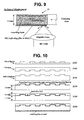
- FIG. 10 shows a schematic process of manufacturing a read-only high-density disk structured in accordance with the present invention.
- FIG. 6 is a sectional view of the first preferred embodiment of a high-density disk structured according to the present invention.
- the embodiment of a high-density disk for example, a HD-DVD according to the present invention has same dimension as a conventional HD-DVD depicted in FIG. 3 , namely, 1.2 mm in thickness and 120 mm in diameter, a center hole of 15 mm diameter and a clamping zone (or clamping area) of 44 mm encircling the center hole.
- its recording layer which contains pit patterns, would be approximately 0.1 mm from its surface confronting the objective lens of an optical pickup as mentioned before.
- the present invention HD-DVD 20 in FIG. 6 has such a distinctive feature that a reflecting film 601 is formed on or a reflecting label is attached to a loop-shaped zone encircling the clamping area on a surface opposite to which a recording layer is disposed in.
- the loop-shaped zone is 45.2 mm in inner diameter and 48 mm in outer diameter.
- the width 2.8 mm is wider than a lead-in area allocated in the recording layer.
- the diameter range may be different from 45.2 mm ⁇ 48 mm only if a lead-in area can be covered enough.
- a disk device Because a lead-in area of a disk contains navigation data referred when searching recorded data, a disk device generally tries to read signals written in a lead-in area first of all when a disk is placed.
- the disk 20 structured as above is placed normally into a disk device as shown in FIG. 6 , the disk surface which the loop-shaped reflecting film 601 or the loop-shaped reflecting label is formed on or attached to is at the back of the recording layer with respect to the objective lens ‘OL’ of an optical pickup.
- a disk device After successful clamping of the high-density disk 20 , a disk device, of which operation is explained with reference to FIG. 4 , conducts a conventional servo-controlling operation, characterized by the operation of the spindle motor 12 , the motor driving unit 13 and the servo controller 15 , to rotate the normally-placed disk 20 at a constant and high speed, and to focus a laser beam exactly onto the lead-in area of the recording layer in order to read out navigation data. After the navigation data is obtained successfully, reproduction of data written on the recording layer can be performed based on the navigation data.
- the disk surface which the loop-shaped reflecting film 601 or the loop-shaped reflecting label is formed on or attached to is in front of the lead-in area of the recording layer with respect to the objective lens ‘OL’ of an optical pickup.
- the disk device conducts a conventional servo-controlling operation, characterized by the operation of the spindle motor 12 , the motor driving unit 13 and the servo controller 15 , to rotate the misplaced disk 20 at a constant and high speed, and to try to obtain an exact focusing onto the lead-in area at the recording layer in order to read out navigation data first.
- the loop-shaped reflecting film 601 or the loop-shaped reflecting label below the lead-in area at the recording layer reflects an incident beam from the optical pickup, light intensity is continuously detected constant during focusing operation, which means that no valid signal is detected in a focusing error signal (FES) while moving up the objective lens ‘OL’.
- FES focusing error signal
- a controlling means (not figured) additionally equipped in the disk device according to the present invention keeps monitoring the FES and it judges that the inserted disk 20 is placed upside down if the monitored FES maintains DC state for a predetermined time while the objective lens ‘OL’ moves toward the bottom surface of the placed disk 20 . If judged misplaced, the controlling means immediately controls the servo controller 15 to stop current focusing operation.
- misplacement of the present disk 20 can be judged from no signal state during focusing operation, movement of the objective lens ‘OL’ is stopped before a collision between the objective lens ‘OL’ and the misplaced disk 20 .
- FIGS. 8 and 9 are sectional views of the second preferred embodiment of a high-density disk structured according to the present invention.
- FIGS. 8 and 9 show normal placement and misplacement of the present disk 21 , respectively.
- a reflecting film 801 or a reflecting label covers almost entire surface opposite to the recording surface the recording layer is in closer proximity to.
- the reflecting film 801 or the reflecting label does not cover the clamping area, preferably.
- the disk 21 of which one surface has been covered with the reflecting film 801 or the reflecting label as shown in FIG. 8 or 9 is misplaced upside down, its misplacement can be judged from no signal in FES in the process of normal focusing servo operation. Consequently, a collision between the objective lens ‘OL’ and the misplaced disk 21 can be prevented basically.
- FIG. 10 shows a schematic process of manufacturing a read-only high-density disk having a reflecting film or a reflecting label on entire non-recording surface excluding a clamping area in accordance with the present invention.
- a metal master is obtained through a mastering process (S 101 ) using an electroplated glass master on which pit patterns of recorded signals are formed.
- stampers are made from the metal master (S 102 ).
- the pit patterns reflecting recorded signals formed on the metal master are copied inversely onto the surface of each stamper.
- a stamper is fixed firmly to an inner plate of an injection molding machine (IMM) (not figured). Afterwards, substrate material such as melt polycarbonate resin at high temperature is injected into the IMM. Then, a disk substrate having right pit patterns is produced from the fixed stamper situated in the IMM (S 103 ). Next, pit pattern side of the disk substrate is coated with aluminum reflecting film (this layer results in a ‘recording layer’) (S 104 ) by a sputtering process in which aluminum metal ions are sputtered and stuck onto the substrate.
- IMM injection molding machine
- a light transmitting layer (also called ‘protective layer’) is then formed on the aluminum reflecting layer by means well known to one of ordinary skill in the art, such as through a spin-coating method or a film bonding method (S 105 ).
- total reflecting material such as aluminum is coated on the bottom of the disk substrate to form a thin reflecting film or a total reflecting label is bonded onto the bottom of the disk substrate, yielding the above-explained high-density disk (S 106 ).
- the thin reflecting film or the reflecting label must be disposed to be overlapped vertically with a lead-in area of the disk.
- the above-explained high-density disk structured in accordance with the present invention and the driving method thereof provide means by which a disk device can prevent a high-density disk, an objective lens, and/or a servo-mechanism from irreparably damaged because of a collision of an optical pickup's objective lens with the high-density disk placed upside down.
- the invention may be applicable to a writable high-density disk as well as a read-only high-density disk without departing from the spirit or essential characteristics thereof.
- the present embodiments are therefore to be considered in all respects as illustrative and not restrictive, the scope of the invention being indicated by the appended claims rather than by the foregoing description and all changes which come within the meaning and range of equivalency of the claims are therefore intended to be embraced therein.
Landscapes
- Physics & Mathematics (AREA)
- Optics & Photonics (AREA)
- Optical Recording Or Reproduction (AREA)
- Optical Head (AREA)
- Optical Record Carriers And Manufacture Thereof (AREA)
- Moving Of The Head For Recording And Reproducing By Optical Means (AREA)
- Manufacturing Optical Record Carriers (AREA)
Applications Claiming Priority (3)
| Application Number | Priority Date | Filing Date | Title |
|---|---|---|---|
| KR2001-0034007 | 2001-06-15 | ||
| KR01-34007 | 2001-06-15 | ||
| KR10-2001-0034007A KR100470027B1 (ko) | 2001-06-15 | 2001-06-15 | 반사표면을 갖는 고밀도 광디스크 및 그 구동방법 |
Publications (2)
| Publication Number | Publication Date |
|---|---|
| US20030007449A1 US20030007449A1 (en) | 2003-01-09 |
| US7761887B2 true US7761887B2 (en) | 2010-07-20 |
Family
ID=19710897
Family Applications (1)
| Application Number | Title | Priority Date | Filing Date |
|---|---|---|---|
| US10/170,543 Expired - Fee Related US7761887B2 (en) | 2001-06-15 | 2002-06-14 | Recording medium having a reflector to prevent traveling of beam to recording layer |
Country Status (6)
| Country | Link |
|---|---|
| US (1) | US7761887B2 (de) |
| EP (1) | EP1274075B1 (de) |
| JP (1) | JP2003006924A (de) |
| KR (1) | KR100470027B1 (de) |
| CN (1) | CN1201312C (de) |
| DE (1) | DE60237266D1 (de) |
Cited By (1)
| Publication number | Priority date | Publication date | Assignee | Title |
|---|---|---|---|---|
| US20120201117A1 (en) * | 2011-02-03 | 2012-08-09 | Sony Corporation | Manufacturing method of optical information recording medium and optical information recording medium |
Families Citing this family (6)
| Publication number | Priority date | Publication date | Assignee | Title |
|---|---|---|---|---|
| KR100470027B1 (ko) * | 2001-06-15 | 2005-02-04 | 엘지전자 주식회사 | 반사표면을 갖는 고밀도 광디스크 및 그 구동방법 |
| TWI260004B (en) * | 2002-03-04 | 2006-08-11 | Ritek Corp | Write-once high-density CD-recordable layer structure and manufacturing method |
| JP3588608B2 (ja) * | 2002-05-31 | 2004-11-17 | 株式会社東芝 | 光ディスク及び光ディスク製造方法 |
| TW594707B (en) * | 2002-10-15 | 2004-06-21 | Lite On It Corp | Method for discriminates an up-side-down disk |
| US7187650B2 (en) * | 2003-06-10 | 2007-03-06 | Cisco Technology, Inc. | Fibre channel frame-mode GFP with distributed delimiter |
| US7159776B2 (en) * | 2005-01-05 | 2007-01-09 | Dell Products L.P. | System and method for optical medium label alignment |
Citations (19)
| Publication number | Priority date | Publication date | Assignee | Title |
|---|---|---|---|---|
| JPS57150147A (en) | 1981-03-10 | 1982-09-16 | Matsushita Electric Ind Co Ltd | Optical type recorder and reproducer |
| US4497049A (en) | 1982-02-25 | 1985-01-29 | Staar S. A. | System for detecting the operative face of a disc carrying data on one face only |
| US4879710A (en) * | 1988-04-20 | 1989-11-07 | Mutsuo Iijima | Optical disc protector and method for applying same |
| US5381392A (en) | 1992-04-24 | 1995-01-10 | Pioneer Electronic Corporation | Optical disk reproducing apparatus for identifying whether the disk is a blank disc, partical disc, or a finalized disk |
| EP0720159A2 (de) | 1994-12-28 | 1996-07-03 | Matsushita Electric Industrial Co., Ltd. | Optisches Aufzeichnungsmedium mit zwei Informationsflächen |
| JPH08273205A (ja) | 1995-03-29 | 1996-10-18 | Victor Co Of Japan Ltd | 光ディスク |
| JPH0991757A (ja) | 1995-09-25 | 1997-04-04 | Sanyo Electric Co Ltd | 光学式情報記録媒体及びその識別方法 |
| EP0798707A2 (de) | 1996-03-29 | 1997-10-01 | Pioneer Electronic Corporation | Optische Platte |
| JPH10124932A (ja) | 1996-10-15 | 1998-05-15 | Dainippon Printing Co Ltd | 光学記録証付き光学記録媒体およびその製造方法 |
| US5787069A (en) * | 1996-09-13 | 1998-07-28 | Digital Armor Inc. | Protective cover for an optical disc |
| WO1999000794A1 (fr) | 1997-06-27 | 1999-01-07 | Sony Corporation | Support d'enregistrement optique et dispositif de disque optique |
| WO1999044199A1 (fr) | 1998-02-24 | 1999-09-02 | Sony Corporation | Support d'enregistrement optique |
| EP0971347A1 (de) | 1996-04-26 | 2000-01-12 | Matsushita Electric Industrial Co., Ltd. | Informationsaufzeichnungsverfahren, informationsaufzeichnungs-/-wiedergabegerät und informationsaufzeichnungsmedium |
| JP2000187882A (ja) | 1998-02-24 | 2000-07-04 | Sony Corp | 光記録媒体 |
| JP2000195102A (ja) | 1998-12-25 | 2000-07-14 | Victor Co Of Japan Ltd | 光型情報担体 |
| JP2000298878A (ja) | 1999-02-12 | 2000-10-24 | Sony Corp | 光記録媒体 |
| US20020060981A1 (en) * | 1999-06-22 | 2002-05-23 | Naohiro Netsu | Optical recording medium and disc cartridge |
| US6649240B2 (en) * | 1999-02-26 | 2003-11-18 | Ricoh Company, Ltd. | Optical information recording medium |
| US6775838B2 (en) * | 2000-09-05 | 2004-08-10 | Tdk Corporation | Optical information medium and its testing method |
Family Cites Families (3)
| Publication number | Priority date | Publication date | Assignee | Title |
|---|---|---|---|---|
| KR950007299B1 (ko) * | 1993-08-31 | 1995-07-07 | 대우전자주식회사 | 라벨층이 증착된 광 디스크 제조법 |
| JPH1153768A (ja) * | 1997-08-01 | 1999-02-26 | Nippon Columbia Co Ltd | 光情報記録媒体 |
| KR100470027B1 (ko) * | 2001-06-15 | 2005-02-04 | 엘지전자 주식회사 | 반사표면을 갖는 고밀도 광디스크 및 그 구동방법 |
-
2001
- 2001-06-15 KR KR10-2001-0034007A patent/KR100470027B1/ko not_active IP Right Cessation
-
2002
- 2002-06-14 EP EP02013174A patent/EP1274075B1/de not_active Expired - Lifetime
- 2002-06-14 CN CNB021243670A patent/CN1201312C/zh not_active Expired - Fee Related
- 2002-06-14 US US10/170,543 patent/US7761887B2/en not_active Expired - Fee Related
- 2002-06-14 DE DE60237266T patent/DE60237266D1/de not_active Expired - Lifetime
- 2002-06-17 JP JP2002175495A patent/JP2003006924A/ja active Pending
Patent Citations (19)
| Publication number | Priority date | Publication date | Assignee | Title |
|---|---|---|---|---|
| JPS57150147A (en) | 1981-03-10 | 1982-09-16 | Matsushita Electric Ind Co Ltd | Optical type recorder and reproducer |
| US4497049A (en) | 1982-02-25 | 1985-01-29 | Staar S. A. | System for detecting the operative face of a disc carrying data on one face only |
| US4879710A (en) * | 1988-04-20 | 1989-11-07 | Mutsuo Iijima | Optical disc protector and method for applying same |
| US5381392A (en) | 1992-04-24 | 1995-01-10 | Pioneer Electronic Corporation | Optical disk reproducing apparatus for identifying whether the disk is a blank disc, partical disc, or a finalized disk |
| EP0720159A2 (de) | 1994-12-28 | 1996-07-03 | Matsushita Electric Industrial Co., Ltd. | Optisches Aufzeichnungsmedium mit zwei Informationsflächen |
| JPH08273205A (ja) | 1995-03-29 | 1996-10-18 | Victor Co Of Japan Ltd | 光ディスク |
| JPH0991757A (ja) | 1995-09-25 | 1997-04-04 | Sanyo Electric Co Ltd | 光学式情報記録媒体及びその識別方法 |
| EP0798707A2 (de) | 1996-03-29 | 1997-10-01 | Pioneer Electronic Corporation | Optische Platte |
| EP0971347A1 (de) | 1996-04-26 | 2000-01-12 | Matsushita Electric Industrial Co., Ltd. | Informationsaufzeichnungsverfahren, informationsaufzeichnungs-/-wiedergabegerät und informationsaufzeichnungsmedium |
| US5787069A (en) * | 1996-09-13 | 1998-07-28 | Digital Armor Inc. | Protective cover for an optical disc |
| JPH10124932A (ja) | 1996-10-15 | 1998-05-15 | Dainippon Printing Co Ltd | 光学記録証付き光学記録媒体およびその製造方法 |
| WO1999000794A1 (fr) | 1997-06-27 | 1999-01-07 | Sony Corporation | Support d'enregistrement optique et dispositif de disque optique |
| WO1999044199A1 (fr) | 1998-02-24 | 1999-09-02 | Sony Corporation | Support d'enregistrement optique |
| JP2000187882A (ja) | 1998-02-24 | 2000-07-04 | Sony Corp | 光記録媒体 |
| JP2000195102A (ja) | 1998-12-25 | 2000-07-14 | Victor Co Of Japan Ltd | 光型情報担体 |
| JP2000298878A (ja) | 1999-02-12 | 2000-10-24 | Sony Corp | 光記録媒体 |
| US6649240B2 (en) * | 1999-02-26 | 2003-11-18 | Ricoh Company, Ltd. | Optical information recording medium |
| US20020060981A1 (en) * | 1999-06-22 | 2002-05-23 | Naohiro Netsu | Optical recording medium and disc cartridge |
| US6775838B2 (en) * | 2000-09-05 | 2004-08-10 | Tdk Corporation | Optical information medium and its testing method |
Cited By (2)
| Publication number | Priority date | Publication date | Assignee | Title |
|---|---|---|---|---|
| US20120201117A1 (en) * | 2011-02-03 | 2012-08-09 | Sony Corporation | Manufacturing method of optical information recording medium and optical information recording medium |
| US8671420B2 (en) * | 2011-02-03 | 2014-03-11 | Sony Corporation | Manufacturing method of optical information recording medium and optical information recording medium |
Also Published As
| Publication number | Publication date |
|---|---|
| CN1392550A (zh) | 2003-01-22 |
| JP2003006924A (ja) | 2003-01-10 |
| EP1274075A3 (de) | 2003-10-29 |
| EP1274075B1 (de) | 2010-08-11 |
| US20030007449A1 (en) | 2003-01-09 |
| KR20020095795A (ko) | 2002-12-28 |
| EP1274075A2 (de) | 2003-01-08 |
| CN1201312C (zh) | 2005-05-11 |
| DE60237266D1 (de) | 2010-09-23 |
| KR100470027B1 (ko) | 2005-02-04 |
Similar Documents
| Publication | Publication Date | Title |
|---|---|---|
| US7215620B2 (en) | Information recording medium with management area having recording identification information | |
| EP0841658B1 (de) | Optische Platte, Gerät zur Aufnahme und Wiedergabe einer optischen Platte und Herstellungsverfahren der optischen Platte | |
| US7515524B2 (en) | High density disk recording medium and apparatus using the same | |
| US7761887B2 (en) | Recording medium having a reflector to prevent traveling of beam to recording layer | |
| US20060114803A1 (en) | Information storage medium, stamper, disc apparatus, and management information playback method | |
| US7484231B2 (en) | High-density disk recording medium having an asymmetrically-shaped center hole and manufacturing method thereof | |
| KR100582955B1 (ko) | 비대칭 상하구조의 중앙홀을 갖는 고밀도 광디스크 및 그 제조방법 | |
| JP2007294110A (ja) | サーボ制御装置 | |
| JP3965758B2 (ja) | 記録担体判別装置および記録担体判別方法 | |
| EP2154683A1 (de) | Mehrschichtiger optischer datenträger | |
| KR100712775B1 (ko) | 고밀도 광디스크 및 그 제조방법 | |
| KR20040024014A (ko) | 고밀도 광디스크와 그에 따른 구동방법 | |
| JP3986702B2 (ja) | 光記録媒体及び光記録媒体用基板 | |
| JPH07272281A (ja) | 高密度記録ができる光ディスク | |
| JP2000235737A (ja) | 光ディスクおよびその製造方法 |
Legal Events
| Date | Code | Title | Description |
|---|---|---|---|
| AS | Assignment |
Owner name: LG ELECTRONICS INC., KOREA, REPUBLIC OF Free format text: ASSIGNMENT OF ASSIGNORS INTEREST;ASSIGNORS:KIM, JIN YONG;PARK, KYUNG CHAN;KIM, WAE YEUL;REEL/FRAME:013300/0713 Effective date: 20020823 |
|
| FEPP | Fee payment procedure |
Free format text: PAYOR NUMBER ASSIGNED (ORIGINAL EVENT CODE: ASPN); ENTITY STATUS OF PATENT OWNER: LARGE ENTITY |
|
| FPAY | Fee payment |
Year of fee payment: 4 |
|
| FEPP | Fee payment procedure |
Free format text: MAINTENANCE FEE REMINDER MAILED (ORIGINAL EVENT CODE: REM.) |
|
| LAPS | Lapse for failure to pay maintenance fees |
Free format text: PATENT EXPIRED FOR FAILURE TO PAY MAINTENANCE FEES (ORIGINAL EVENT CODE: EXP.); ENTITY STATUS OF PATENT OWNER: LARGE ENTITY |
|
| STCH | Information on status: patent discontinuation |
Free format text: PATENT EXPIRED DUE TO NONPAYMENT OF MAINTENANCE FEES UNDER 37 CFR 1.362 |
|
| FP | Lapsed due to failure to pay maintenance fee |
Effective date: 20180720 |