US7734206B2 - Image forming apparatus - Google Patents
Image forming apparatus Download PDFInfo
- Publication number
- US7734206B2 US7734206B2 US12/046,711 US4671108A US7734206B2 US 7734206 B2 US7734206 B2 US 7734206B2 US 4671108 A US4671108 A US 4671108A US 7734206 B2 US7734206 B2 US 7734206B2
- Authority
- US
- United States
- Prior art keywords
- image
- bearing member
- driving torque
- toner
- image bearing
- Prior art date
- Legal status (The legal status is an assumption and is not a legal conclusion. Google has not performed a legal analysis and makes no representation as to the accuracy of the status listed.)
- Expired - Fee Related, expires
Links
Images


Classifications
-
- G—PHYSICS
- G03—PHOTOGRAPHY; CINEMATOGRAPHY; ANALOGOUS TECHNIQUES USING WAVES OTHER THAN OPTICAL WAVES; ELECTROGRAPHY; HOLOGRAPHY
- G03G—ELECTROGRAPHY; ELECTROPHOTOGRAPHY; MAGNETOGRAPHY
- G03G15/00—Apparatus for electrographic processes using a charge pattern
- G03G15/50—Machine control of apparatus for electrographic processes using a charge pattern, e.g. regulating differents parts of the machine, multimode copiers, microprocessor control
- G03G15/5033—Machine control of apparatus for electrographic processes using a charge pattern, e.g. regulating differents parts of the machine, multimode copiers, microprocessor control by measuring the photoconductor characteristics, e.g. temperature, or the characteristics of an image on the photoconductor
- G03G15/5041—Detecting a toner image, e.g. density, toner coverage, using a test patch
-
- G—PHYSICS
- G03—PHOTOGRAPHY; CINEMATOGRAPHY; ANALOGOUS TECHNIQUES USING WAVES OTHER THAN OPTICAL WAVES; ELECTROGRAPHY; HOLOGRAPHY
- G03G—ELECTROGRAPHY; ELECTROPHOTOGRAPHY; MAGNETOGRAPHY
- G03G15/00—Apparatus for electrographic processes using a charge pattern
- G03G15/06—Apparatus for electrographic processes using a charge pattern for developing
- G03G15/08—Apparatus for electrographic processes using a charge pattern for developing using a solid developer, e.g. powder developer
- G03G15/0822—Arrangements for preparing, mixing, supplying or dispensing developer
- G03G15/0848—Arrangements for testing or measuring developer properties or quality, e.g. charge, size, flowability
- G03G15/0849—Detection or control means for the developer concentration
- G03G15/0853—Detection or control means for the developer concentration the concentration being measured by magnetic means
-
- G—PHYSICS
- G03—PHOTOGRAPHY; CINEMATOGRAPHY; ANALOGOUS TECHNIQUES USING WAVES OTHER THAN OPTICAL WAVES; ELECTROGRAPHY; HOLOGRAPHY
- G03G—ELECTROGRAPHY; ELECTROPHOTOGRAPHY; MAGNETOGRAPHY
- G03G15/00—Apparatus for electrographic processes using a charge pattern
- G03G15/06—Apparatus for electrographic processes using a charge pattern for developing
- G03G15/08—Apparatus for electrographic processes using a charge pattern for developing using a solid developer, e.g. powder developer
- G03G15/0822—Arrangements for preparing, mixing, supplying or dispensing developer
- G03G15/0887—Arrangements for conveying and conditioning developer in the developing unit, e.g. agitating, removing impurities or humidity
- G03G15/0891—Arrangements for conveying and conditioning developer in the developing unit, e.g. agitating, removing impurities or humidity for conveying or circulating developer, e.g. augers
- G03G15/0893—Arrangements for conveying and conditioning developer in the developing unit, e.g. agitating, removing impurities or humidity for conveying or circulating developer, e.g. augers in a closed loop within the sump of the developing device
-
- G—PHYSICS
- G03—PHOTOGRAPHY; CINEMATOGRAPHY; ANALOGOUS TECHNIQUES USING WAVES OTHER THAN OPTICAL WAVES; ELECTROGRAPHY; HOLOGRAPHY
- G03G—ELECTROGRAPHY; ELECTROPHOTOGRAPHY; MAGNETOGRAPHY
- G03G15/00—Apparatus for electrographic processes using a charge pattern
- G03G15/50—Machine control of apparatus for electrographic processes using a charge pattern, e.g. regulating differents parts of the machine, multimode copiers, microprocessor control
- G03G15/5033—Machine control of apparatus for electrographic processes using a charge pattern, e.g. regulating differents parts of the machine, multimode copiers, microprocessor control by measuring the photoconductor characteristics, e.g. temperature, or the characteristics of an image on the photoconductor
-
- G—PHYSICS
- G03—PHOTOGRAPHY; CINEMATOGRAPHY; ANALOGOUS TECHNIQUES USING WAVES OTHER THAN OPTICAL WAVES; ELECTROGRAPHY; HOLOGRAPHY
- G03G—ELECTROGRAPHY; ELECTROPHOTOGRAPHY; MAGNETOGRAPHY
- G03G15/00—Apparatus for electrographic processes using a charge pattern
- G03G15/50—Machine control of apparatus for electrographic processes using a charge pattern, e.g. regulating differents parts of the machine, multimode copiers, microprocessor control
- G03G15/5054—Machine control of apparatus for electrographic processes using a charge pattern, e.g. regulating differents parts of the machine, multimode copiers, microprocessor control by measuring the characteristics of an intermediate image carrying member or the characteristics of an image on an intermediate image carrying member, e.g. intermediate transfer belt or drum, conveyor belt
- G03G15/5058—Machine control of apparatus for electrographic processes using a charge pattern, e.g. regulating differents parts of the machine, multimode copiers, microprocessor control by measuring the characteristics of an intermediate image carrying member or the characteristics of an image on an intermediate image carrying member, e.g. intermediate transfer belt or drum, conveyor belt using a test patch
Definitions
- the present invention relates to an image forming apparatus such as copying machines, and laser beam printers wherein there is applied electrostatic recording system or electrophotographic system in which the electrostatic image formed on an image bearing member is developed by the use of a developer containing a toner and a carrier.
- a two-component developer prepared by mixing principally a non-magnetic toner with a magnetic carrier is widely used (hereinafter referred to as “two-component developing system”) as a developer used in an image forming apparatus due to the increase in quality and speed in full-color image forming apparatuses in recent years.
- a developing method wherein a two-component developer there is a method wherein a developer containing a toner and a carrier is blended by means of a stirring/blending member, and the resulting blend is fed to the surface of a developer support.
- the developer support fixedly houses a magnetic roll in which a plurality of south poles and north poles are disposed alternately with each other, and the developer is in a condition wherein the developer forms a brush outline on the surface of the developer support by the magnetic force (hereinafter referred to as “magnetic brush”).
- the developer magnetic brush supported on the surface of the developer support is allowed to be in contact with or to approach the surface of a photosensitive member, and a development bias voltage is applied between the developer support and the photosensitive member, whereby the toner is allowed to adhere onto an electrostatic image to complete the development.
- the electrostatic force having the tendency wherein the carrier adheres onto the photosensitive member is the maximum in the surface potential area in a non-image portion (Vd electric potential) being an area charged; however, a higher magnetic force than the above-described electrostatic force is applied to the development sleeve, whereby it may be arranged in such that the carrier does not adhere to the photosensitive member.
- a control method for toner supply includes, for example, a method for applying toner density detection unit (toner density detection system) such as a light detection system or an inductance detection system, and a patch detection system (image density detection system).
- toner density detection system such as a light detection system or an inductance detection system
- patch detection system image density detection system
- the charging amount of a carrier due to the countercharge of the toner is increased accordingly.
- the force due to an electric field increases more than the magnetic force of a magnetic roll, so that the carrier is developed in the non-image area on an electrostatic image retaining member, resulting in beads carry over.
- the beads carry over appears as described above, when a developed toner layer on a photosensitive member is transferred to a transfer material such as a paper in a transfer portion, the carrier is transferred in the condition wherein the carrier is developed on the paper as it stands, and it results in decrease in image quality.
- duration of life decreases due to damaging the surface of a photosensitive member in the case that the photosensitive member is cleaned by means of a cleaning member, besides decrease in image quality and decrease in duration of life occur due to streaks produced by damaging a cleaning member, a transfer device, or a fixing device.
- JP-A No. 2006-119380 there is proposed an image forming apparatus which detects the presence or absence of beads carry over on a photosensitive member by means of an optical sensor, and allows the photosensitive member to isolate from a transfer device based on the detection result.
- image forming apparatuses which detect the beads carry over on a photosensitive member by means of an optical detecting unit.
- JP-A No. H05-66678 there is proposed an image forming apparatus wherein an electromagnet is provided on the downstream side of the transfer direction of a photosensitive member, and the electromagnet being in a roller-shaped and adapted to be rotated attracts the carrier adhered on the photosensitive member to remove the carrier.
- JP-A No. 2003-57939 there is proposed that the occurrence of beads carry over is predicted in the case that a toner density detection result in a development device is lower than a certain threshold value to stop an image forming operation in the image forming apparatus wherein a toner density detection system such as an optical detection system, or an inductance detection system is applied.
- a toner density detection system such as an optical detection system, or an inductance detection system is applied.
- the optical detection unit as disclosed in JP-A No. 2006-119380 exhibits poor detection accuracy of beads carry over, and further cannot detect the whole area of a photosensitive member in the main scanning direction thereof. Consequently, there are a variety of problems such that a carrier cannot be detected other than at the positions where optical sensors are provided, so that the proposed optical detection unit has been not useful.
- the unit as disclosed in JP-A No. H05-66678 is a unit for only removing a carrier from a photosensitive member, there is a limit in the recovery capacity in the case that beads carry over increases further depending on a development condition, and consequently, there is also such a fear that the carrier adhered cannot be recovered. Besides, the unit does not suppress fundamentally beads carry over in a development device.
- the purpose of the present invention is to detect beads carry over with high accuracy and prevent such beads carry over.
- an image forming apparatus comprises the followings: an image bearing member on which an electrostatic image is formed;
- a development device which allows a developer containing a toner and a carrier to be supported on a developer support, whereby the electrostatic image is developed to form a toner image
- an image density detection device which detects a density of the image formed with the toner
- a supply device which supplies the toner to the development device based on the result of detection by the image density detection device
- a cleaning device provided in contact with the image bearing member to clean the surface of the image bearing member
- a driving torque detection device which detects the driving torque in case of driving the image bearing member
- controller which controls the toner concentration in the developer by means of the supply device in response to a value of the driving torque so as to suppress the transition of the carrier to the image bearing member.
- an image forming apparatus may comprise an image bearing member on which an electrostatic image is formed;
- a development device which allows a developer containing a toner and a carrier to be supported on a developer support, whereby the electrostatic image is developed to form a toner image
- a toner density detection device which detects a toner density of the developer in the development device
- a supply device which supplies the toner to the development device based on the result of detection by the toner density detection device
- a cleaning device provided in contact with the image bearing member to clean the surface of the image bearing member
- a driving torque detection device which detects the driving torque in case of driving the image bearing member
- controller which controls the toner concentration in the developer by means of the supply device in response to a value of the driving torque so as to suppress the transition of the carrier to the image bearing member.
- an image forming apparatus comprises the followings: a charging device which charges an image bearing member;
- an exposure device which exposes a region charged in the image bearing member being charged by the charging device to form an electrostatic image
- a development device which allows a developer containing a toner and a carrier to be supported on a developer support, and which provides an electric potential difference between the developer support and the electrostatic image, whereby the electrostatic image is developed to form a toner image;
- a cleaning device provided in contact with the image bearing member to clean the surface of the image bearing member
- a driving torque detection device which detects the driving torque in case of driving the image bearing member
- a controller which drives the image bearing member while providing a predetermined electric potential difference between the region charged in the image bearing member and the developer support in case of non-image formation, conducts a driving torque detecting operation with respect to the image bearing member by means of the driving torque detection device, and changes the electric potential difference between the region charged in the image bearing member and the developer support in case of image formation in response to the value of the driving torque detected so as to suppress the transition of the carrier to the image bearing member.
- FIG. 1 is a schematic constitutional view illustrating an example of an image forming apparatus.
- FIG. 2 is an explanatory view for describing a development device and a toner supply device.
- FIG. 3 is an explanatory view for describing the development device.
- FIG. 4 is a diagram for describing the state of unit block supply.
- FIG. 5 is a flowchart for describing the toner supply according to a video counting system.
- FIG. 6 is a flowchart for describing the toner supply in the case that a video counting system is used together with a patch detection system.
- FIG. 7 is a diagram for describing such fact that a follow-up manner of the number of unit block supply differs in the case that the density signal of a patch image is in a predetermined value or less from the case that the density signal of the patch image is more than the predetermined value.
- FIG. 8 is a diagram for describing the operation steps of an image forming apparatus.
- FIG. 9 is a block diagram for describing a manner for detecting a driving torque.
- FIG. 10 is a diagram illustrating a relationship between a driving torque and an electric current value of a DC servomotor.
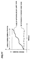
- FIG. 11 is a diagram for describing a state of varying the driving torque in the case that beads carry over arises.
- FIG. 12 is a diagram for describing the detection timing of a driving torque and a manner for detecting the driving torque.
- FIG. 13 is a flowchart for compensating a patch reference value Vref in a first embodiment and a third embodiment.
- FIG. 14 is a flowchart for compensating a Vback electric potential in a second embodiment.
- FIG. 15 is a diagram for describing a photosensitive drum electric potential Vd and a development potential Vdc in case of normal image formation and in case of non-image formation in the second embodiment.
- FIG. 1 is a schematic constitutional view showing an image forming apparatus 100 of the present embodiment.
- the image forming apparatus 100 is an electrophotographic system full-color printer having four image forming sections 1 Y, 1 M, 1 C, and 1 Bk provided corresponding to four colors of yellow, magenta, cyan, and black.
- the image forming apparatus 100 may form a four full-color image on a recording material (recording paper, plastic film, cloth etc.) in response to an image signal from host equipment.
- the host equipment means herein an original scanning device (not shown) connected to an image forming apparatus main body, a personal computer connected to be able to communicate with the image forming apparatus main body, or the like equipment.
- the image forming section 1 is provided with a cylindrical type photosensitive member, i.e. a photosensitive drum 2 as the image bearing member.
- the photosensitive drum 2 is rotary driven in the direction of the arrow in the drawing.
- a charging roller 3 being a charging unit
- a development device 4 being a developing unit
- a primary transfer roller 5 being a transfer unit
- a cleaning device 6 being a cleaning unit.
- the cleaning device 6 is provided with a cleaning blade being in contact with the photosensitive drum, and the surface of the photosensitive drum is cleaned by the cleaning blade.
- a laser scanner (exposure device) 7 being an exposure unit is positioned over the photosensitive drum 2 in the upper direction of the drawing.
- An intermediate transfer belt 16 is disposed in opposite to the photosensitive drum 2 of the respective image forming sections 1 . Furthermore, a secondary transfer roller 15 and a secondary transfer counter roller 10 are disposed under the four photosensitive drums 2 so as to sandwich the intermediate transfer belt 16 and the recording material support 8 .
- the intermediate transfer belt 16 is stretched by a driving roller 9 , the secondary transfer counter roller 10 , and a tension roller 12 .
- the intermediate transfer belt 16 is driven by the driving roller 9 to revolvingly travel in the direction of the arrow in the drawing thereby to convey a toner image to an abutting section upon the recording material P.
- the toner image is transferred to the recording material P from the intermediate transfer belt 16 ; thereafter the toner image is heat-fused on the recording material P by means of a fuser 13 .
- the surface of the rotating photosensitive drum 2 is uniformly charged by the charging roller 3 .
- a charging bias is applied to the charging roller 3 from a charging bias power source.
- the photosensitive drum 2 is exposed by laser beams in response to image signals generated from the exposure device 7 .
- the electrostatic image in response to the image signals is formed on the photosensitive drum 2 .
- the electrostatic image on the photosensitive drum 2 is visualized with the toner contained in the development device 4 to obtain a visual image.
- reversal development system wherein a toner is allowed to adhere to a bright portion potential exposed by laser beams is applied.
- a toner image is formed on the photosensitive drum 2 by means of the development device 4 , and the toner image is transferred primarily to the intermediate transfer belt 16 .
- the toner left on the surface of the photosensitive drum 2 (transfer residual toner) after the primary transfer is removed by the cleaning device 6 .
- the operation as described above is successively carried out in respect of four color toners of yellow, magenta, cyan, and black, and the four color toner images are superposed on the intermediate transfer belt 16 one another.
- the recording material P contained in a recording material containing cassette (not shown) is conveyed in proper timing with the formation timing of the toner image by means of supply rollers 14 and the recording material support 8 .
- a secondary transfer bias is applied to a secondary transfer roller 15 , whereby the four-colored toner image on the intermediate transfer belt 16 is transferred secondarily in a lump onto the recording material P supported on the recording material support 8 .
- the recording material P is separated from the photosensitive drum, and conveyed to the fuser 13 being a fixing unit.
- the toners are heated and pressurized by the fuser 13 , the toners on the recording material P are fused and mixed to obtain a full-colored permanent image. Thereafter, the recording material P is discharged outside the apparatus.
- the toner left on the intermediate transfer belt 16 which has not been completely transferred in the secondary transfer section is removed by an intermediate transfer belt cleaner 18 , and consequently, a series of operations is completed.
- a desired unicolored or multicolored image can be formed by using only a desired image forming section or image forming sections in the present embodiment.
- the development device 4 and the toner supply device 19 are described by referring to FIGS. 2 and 3 .
- the constitutions of yellow, magenta, cyan, and black development devices and toner supply devices are the same as that of the others one another.
- the development device 4 has a developer container 80 containing a developer.
- a two-component developer including principally a nonmagnetic toner (toner) and a magnetic carrier (carrier) as the developer is contained in the developer container 80 .
- a toner density of the developer in the initial condition is 7% by weight in the present embodiment.
- the value should be appropriately adjusted depending upon the charging amount of a toner, the particle diameter of a carrier, the constitution of an image forming apparatus and the like. Accordingly, it is not necessarily to follow the numerical value as described above.
- the target value of an adequate toner density is referred to as “toner density target value” in the present embodiment.
- a part opposed to the photosensitive drum 2 of the development container 80 is opened, and a development sleeve 61 being a developer support is rotatably disposed so as to partly expose with respect to the opening.
- the development sleeve 61 is made of a nonmagnetic material, and involves a stationary magnet 62 being a magnetic field generation unit.
- the magnet 62 has a plurality of magnetic poles along the outer circumference thereof.
- the development sleeve 61 rotates in the direction of the arrow in the drawing to maintain the two-component developer in the development container 80 in the form of laminate, and supports and conveys the developer to a development region opposed to the photosensitive drum 2 .
- the developer supported on the development sleeve 61 forms a magnetic brush in the development region. Then, the magnetic brush is either allowed to be in contact with or close to the surface of the photosensitive drum 2 to supply the toner in the two-component developer in response to the electrostatic image to be formed on the surface of the photosensitive drum 2 thereby to develop the electrostatic image.
- a predetermined development bias is applied to the development sleeve 61 in case of at least developing operation, whereby the toner is shifted to the photosensitive drum 2 by the action of the electric field generated between the photosensitive drum 2 and the development sleeve 61 .
- a developer amount restriction unit 67 for restricting a thickness of a developer layer by the action of a magnetic field in cooperation with the magnet 62 is provided on the more upstream side in the rotating direction of the development sleeve 61 than the development region.
- the remaining developer after developing the electrostatic image on the photosensitive drum 2 is conveyed in accordance with the rotation of the development sleeve 61 , and recovered in a development chamber (first developer containment chamber) 81 , which will be described hereunder, of the development container 80 .
- the development container is divided by a partition wall 85 into substantially two parts of the development chamber 81 (the side close to the development sleeve 61 ) and an agitation chamber (second developer containment chamber) 82 (the side distant from the development sleeve 61 ).
- the development chamber 81 and the agitation chamber 82 extend in the axial direction of the development sleeve 61 in the present embodiment.
- the partition wall 85 does not reach the opposed end portions in the longitudinal direction inside the development container 80 , i.e. side walls 86 and 87 , whereby a first communication portion 83 and a second communication portion 84 permitting a developer to pass through both the development chamber 81 and the agitation chamber 82 are formed.
- the development chamber 81 and the agitation chamber 82 are provided with a circulation unit for circulating a developer therebetween.
- the circulation unit has a first screw 63 and a second screw 64 along the longitudinally axial direction of the development chamber 81 and the agitation chamber 82 as convey members convey and agitate the developer, respectively.
- the developer is blended and agitated while circulating in the development container 2 by the first screw 63 and second screw 64 .
- the direction of circulating the developer in the development device 4 of the present embodiment is the direction from the back side of FIG. 2 towards the front side thereof in the development chamber 81 , while it is the direction from the front side of FIG. 2 towards the back side thereof in the agitation chamber 82 (the directions of the arrows D in FIG. 3 ).
- the driving force from a driving source 70 being a driving motor provided on the image forming apparatus main body is transmitted to the development sleeve 61 through a revolving shaft 71 being a drive transmission unit. Furthermore, the driving force is transmitted to the first screw 63 and the second screw 64 through a gear system of 72 a , 72 b , and 72 c being a drive transmission unit.
- the first screw 63 and the second screw 64 have revolving shafts 63 a and 64 a disposed substantially in parallel to the longitudinally axial direction of the development chamber 81 and the agitation chamber 82 , and spirally shaped convey portions (blade portions, spiral members) 63 b and 64 b provided around the each revolving shafts, respectively.
- both the first and the second screws 63 and 64 have the revolving shafts 63 a and 64 a each having 6 mm axial diameter; and the spirally shaped convey portions 63 b and 64 b each having 16 mm diameter are provided with 15 mm interval on the axial circumferences of the revolving shafts, respectively.
- first return member 65 and a second return member 66 on the downstream end portions in the convey directions of a developer in the first screw 63 and the second screw 64 , respectively.
- the return member 65 and the return member 66 are formed with the spirally shaped convey portions (blade portions) on the axial circumferences of the revolving shafts 63 a and 64 a , respectively.
- the first return member 65 is coaxially provided on the first screw 63 so as to reverse the convey direction of the developer (the direction of the arrow r 1 in the drawing), while the second return member 66 is coaxially provided on the second screw 64 so as to reverse the convey direction of the developer (the direction of the arrow r 2 in the drawing).
- the developer is returned in the reverse directions against the convey directions (the directions D of the arrows in FIG. 3 ) in the respective downstream end portions in the convey directions of the developer in the first screw 63 and the second screw 64 , whereby the developer is smoothly delivered and received in the first communication portion 83 and the second communication portion 84 , respectively.
- the toner in a two-component developer is consumed by the above-mentioned developing operation. Consequently, the toner density in the developer contained in the developer container 80 decreases gradually. Accordingly, a toner is supplied to the developer container 80 by means of the toner supply device 19 shown in FIG. 2 .
- the toner supply device 19 has a toner container (toner supply tank, toner storage section) 50 containing the toner to be supplied to the development device 4 .
- the toner container 50 is provided with a toner supply port 51 b .
- the toner container 50 is further provided with a toner supply screw 51 a being a toner supply unit for conveying the toner towards the toner supply port 51 b.
- the toner in the developer container 2 is consumed and the toner density in a developer is decreased. Accordingly, it is required to control the toner density within a desired range by supplying properly the toner.
- a system using two systems at the same time is applied in order to control the toner density within a desired range.
- One of which is a video count system
- the other is a patch detection system.
- the video count system is a system wherein a time of revolution of the toner supply screw 51 a is controlled based on the video count number of the density signal in an image information signal.
- the patch detection system is a control system wherein first, a reference toner image (patch image) is formed on the photosensitive drum 2 , the resulting reference toner image is transferred onto the intermediate transfer belt 16 , and then, the density signal of the patch image is detected by the optical sensor 17 being an image density detection unit.
- the optical sensor 17 detects the quantity of reflected light as a density signal in the case that the patch image is illuminated by a light.
- the density signal is then compared with the initial reference signal which has been stored previously, and the driving time of the toner supply screw 51 a which is determined by a first toner supply control unit is compensated based on the comparison data.
- a toner density is controlled principally by the video count system.
- the level of the output signal in an image signal processing circuit is counted in every pixel, and when the count number is integrated by pixels of an original paper size, the video count number per an original is determined.
- the maximum video count number in an A4 size original is 3884 ⁇ 106 in 400 dpi and 256 gradation sequence.
- the video count number corresponds to a prospective amount of toner consumption, thus, an appropriate time of rotation of the toner supply screw 51 a is determined from the conversion table indicating a correspondence relationship between the video count number and the time of rotation of the toner supply screw 51 a , and the toner is supplied accordingly.
- the time of rotation of the toner supply screw 51 a per 1 unit block is set in 0.4 second in the present embodiment. Accordingly, the time of rotation of the toner supply screw 51 a per an image is limited to 0.4 second or the integral multiples thereof.
- FIG. 4 shows the state of a specific toner supply.
- the time of rotation of the toner supply screw 51 a determined by means of the conversion table from the above-described video count number is 0.52 second.
- the number of the unit block supply supplied per an image in the next image forming operation is one (the time of rotation of the toner supply screw 51 a is 0.4 second).
- the toner supply of the remaining 0.12 second is stored as a remainder. The remainder is added to the time of rotation of the toner supply screw 51 a determined from the next video count numbers.
- the flow of the above-described processing is shown in FIG. 5 .
- the advantage obtained by limiting the time of rotation of the toner supply screw 51 a to only the integral multiples of a predetermined unit time is in that the amount of a toner supply in each time is stabilized.
- the compensation of the amount of toner supply is applied in a predetermined interval using a patch detection system (hereinafter referred to as “patch detection mode”).
- the interval is set up in every 30 pieces of a small size original (for example, A4 lengthwise).
- the electrostatic image of a patch image having a certain area is formed on the photosensitive drum 2 .
- the electrostatic image is developed by a predetermined development contrast voltage to obtain the patch image.
- the patch image is transferred onto the intermediate transfer belt 16 , and thereafter, the density signal thereof is detected by the optical sensor 17 being an optical density detection unit which is opposed to the intermediate transfer belt 16 .
- the density signal Vsig is compared with the reference signal Vref which has been stored previously in a memory.
- Vsig ⁇ Vref ⁇ 0 it is judged that the density of the patch image is low, i.e. the developer density is low. Then, a required amount of toner supply and the time of rotation of the toner supply screw are determined from the difference between the Vref and the Vsig. Hence, the compensation is made in such a fashion that the time of rotation is added to the time of rotation determined by the video count system.
- Vsig ⁇ Vref ⁇ 0 it is judged that the density of the patch image is high, i.e. the developer density is high. Then, the unnecessary amount of toner and the stop time of the toner supply screw 51 a in response to the unnecessary amount of toner are determined from the difference between the Vref and the Vsig. Hence, the compensation is made in such a fashion that the time determined is subtracted from the time of rotation determined by the video count system.
- the time of rotation of the toner supply screw 51 a is allowed to increase from the detection result of the patch detection mode, i.e. in the case that the number of unit block supply is added, it is arranged in such that only 1 block per a piece of image is added as shown in FIG. 7 .
- the developer used in the present embodiment is described hereinafter.
- a two-component developer including principally a nonmagnetic toner (toner) and a magnetic carrier (carrier) is used in the present embodiment.
- the toner includes a binder resin, colorant, colored resin particles containing the other additives according to need, and colored particles to which an external additive such as a colloidal silica impalpable powder is externally added.
- the toner is a negatively charged polyester base resin manufactured by a crushing method, and the volume average particle diameter thereof is preferably 5 ⁇ m or more and 9 ⁇ m or less. In the present embodiment, the volume average particle diameter is 6.2 ⁇ m.
- iron with an oxidized surface or a surface without oxidize a metal such as cobalt, manganese, chromium, and rare earths, the alloys thereof, or the oxide ferrites may be preferably used.
- a manufacturing method for these magnetic particles is not particularly restricted.
- a weight average particle diameter of the carrier is 20 to 50 ⁇ m, and preferably 30 to 40 ⁇ m.
- An electric resistivity of the carrier is 10 7 ⁇ cm or more, and preferably 10 8 ⁇ cm or more. In the present embodiment, a carrier having 10 8 ⁇ cm electric resistivity is used.
- a volume average particle diameter of the toner used in the present embodiment is measured by means of the following devices and method.
- As measuring instruments Coulter counter type TA-II (manufactured by Coulter Electronics Ltd.), an interface for outputting a number-average distribution and a volume-average distribution (manufactured by Nikkaki Co.), and a CX-I personal computer (manufactured by Cannon Inc.) are used.
- 1% NaCl aqueous solution prepared by using first grade sodium chloride is used as an electrolytic aqueous solution.
- the measuring method is as follows.
- a surfactant preferably alkylbenzene sulfonate is added as a dispersant to 100 to 150 ml of the above-described electrolytic aqueous solution, and to which 0.5 to 50 mg of a sample to be measured is added.
- the electrolytic aqueous solution into which the sample is suspended is subjected to dispersion treatment by an ultrasonic disperser for about 1 to 3 minutes, and the particle size distribution is measured as to particles of 2 to 40 ⁇ m with the use of 100 ⁇ m aperture as an aperture by means of the above-described Coulter counter type TA-II, whereby a volume average distribution is determined. From the volume average distribution thus obtained, a volume average particle diameter is obtained.
- FIG. 8 The operation process chart of the above-described image forming apparatus is illustrated in FIG. 8 .
- the process corresponds to a in a start-up (activation) operation period (warming period) of the image forming apparatus.
- the main power source switch of the image forming apparatus is turned ON to start up the main motor of the image forming apparatus, whereby the preparatory operation of required process equipment is implemented.
- the driving of the main motor is stopped, and the image forming apparatus is kept in a standby (waiting) condition until a print job start signal is input.
- the process corresponds to a period wherein the main motor is driven again based on inputting a print job start signal to implement preliminary operations of the print job of required process equipment. More practically, the process is conducted in the order of the following steps: 1. the image forming apparatus receives the print job start signal, 2. the image is developed by a formatter (the developing time varies depending on the data amount of the image or the processing speed of the formatter), and 3. the preliminary rotation process starts.
- the step shifts succeedingly to the preliminary rotation process after completing the preliminary multiple-rotation process without accompanying the above-described step 2. of the standby.
- the image formation process is implemented to output a recording material on which an image has been formed.
- the image formation process is repeated to output successively a required number of recording materials on each of which the image has been formed.
- the process corresponds to that for an interval as to the rear end of a recording material P and the front end of the following recording material P, and it means a period for the condition wherein a paper does not pass through in a transfer section or a fuser.
- the main motor is driven continuously for a predetermined period of time either after outputting a recording material on which an image has been formed in case of the print job for only a piece of the recording material, or after outputting the last recording material on which an image has been formed in a continuous print job in case of implementing the continuous print job.
- the process corresponds to a period for implementing a post-operation of the print job for required process equipment by the above operation.
- the implementing a print job period in process d is the period of forming an image
- the preliminary multiple-rotation process period in process a is the period of forming an image
- the preliminary rotation process period in process c is the preliminary rotation process period in process c
- the paper interval process period in process e is the post-rotation process period in process f
- the case of non-image formation means at least one case of the above-described cases of preliminary multiple-rotation process, preliminary rotation process, paper interval process, and post-rotation process, and it consequently means predetermined periods of time in the process (processes).
- a predetermined voltage is applied to the charging roller 3 and the development sleeve 61 while at least the photosensitive drum 2 and the development sleeve 61 are rotated.
- a prescribed electric potential difference (electric potential Vback) is maintained between the photosensitive drum 2 and the development sleeve 61 .
- the photosensitive drum 2 and the development sleeve 61 are rotated in case of non-image formation, whereby the appearance of fog and beads carry over is prevented.
- the surface electric potential (electric potential Vd) of the photosensitive drum 2 is ⁇ 500 V
- a development bias voltage (Vdc) is ⁇ 300 V
- an electric potential Vback is 200 V.
- the photosensitive drum 2 is rotary driven by a DC servomotor 150 being a motor (driving device); and the DC servomotor 150 is driven by a motor driving circuit 151 .
- a control section 152 being a control unit (controller) has a CPU, memories and the like inside thereof to control respective devices.
- the control section 152 detects the speed of the DC servomotor 150 by means of a rotation speed detection device (not shown), whereby the electric current value to be supplied to the DC servomotor 150 from the motor driving circuit 151 is controlled.
- the control section 152 is provided with units which perform the other control operations in the image forming apparatus. Examples of these units include a changing unit for changing a reference value in response to the value of the driving torque detected, a supply control unit for controlling a toner amount to be supplied to a development unit by means of a toner supply unit, and the like units.
- the electric current value to be supplied to the DC servomotor 150 must be increased in order to keep the rotation speed of the DC servomotor 150 constant.
- the relationship between a motor load current and a driving torque is in a substantially linear proportional relation as shown in FIG. 10 .
- the relation table between the motor load current and the driving torque of FIG. 10 is stored in a memory section (memories, hard disc and the like) in the control section 152 , so that when a motor load current value is detected, the driving torque of the photosensitive drum 2 can be calculated.
- the mechanism as described is used as a driving torque detection unit, and to calculate the driving torque as mentioned herein is referred to as “implementation of detecting operation of a driving torque”.
- the driving torque of the photosensitive drum 2 is detected by means of the above-mentioned units.
- Concerning the timing of detecting a driving torque in the present embodiment there is one timing for each the above-mentioned non-image formation cases of preliminary rotation process, paper interval process, and post-rotation process.
- the reason for detecting a driving torque in non-image formation cases is as follows. Namely, the electric potential Vback is in a uniform condition over the whole region in the main scanning direction and the sub-scanning direction of the photosensitive drum in case of non-image formation. For this reason, the driving torque of the photosensitive drum can be accurately detected always in the same electric potential condition.
- the electric potential in the main scanning direction and the sub-scanning direction of the photosensitive drum becomes a non-uniform condition depending on the image pattern to be formed in case of image formation. Hence, it becomes difficult to detect the presence or absence of beads carry over in high precision.
- FIG. 11 shows the fluctuation transition of driving torque of a photosensitive drum in the case that beads carry over appears actually in a certain paper interval.
- the driving torque of the photosensitive drum rises.
- the driving torque in a predetermined period of the respective cases of preliminary rotation process, paper interval process, and post-rotation process is detected.
- a difference between the maximum value and the minimum value of the driving torque detected in each of the non-image formation regions exceeds a predetermined threshold value (0.02 N.m in the present embodiment) is consecutively obtained a predetermined number of times (consecutive five times of the results in the present embodiment).
- the value of the reference signal Vref in the above-mentioned patch detection method is compensated, and the toner density of a developer in a development unit is increased.
- the motor load current value applied to the DC servomotor 150 in a certain predetermined period of time (0.4 second in the present embodiment) in the case of paper interval process is consecutively measured.
- the driving torque of the photosensitive drum 2 is calculated by means of the relational table of FIG. 10 .
- a difference F (H-L) between the maximum value F (H) and the minimum value F (L) of the driving torque calculated is obtained.
- Beads carry over is detected herein by the calculation of the difference F (H-L) between the maximum value F (H) and the minimum value F (L) of the driving torque calculated as shown in FIG. 12 .
- F (H-L) the difference between the maximum value F (H) and the minimum value F (L) of the driving torque calculated as shown in FIG. 12 .
- a disadvantage arises.
- An example of the factors includes a case where such a condition that a toner is exhausted in a blade portion of the cleaning device 6 continues according to the status of use of an image forming apparatus.
- the present embodiment is arranged in such that a driving torque is not detected until 10 pieces of image formation are completed after the value of a reference signal Vref is compensated in the case where it is judged that beads carry over appears. This is because a time lag occurs before a toner density increases as a result of toner supply after the compensation of the Vref.
- the present embodiment it is also arranged in such that the value of a patch reference signal Vref is compensated in every 20 levels in the case that beads carry over arises.
- the number of times for compensating patch reference signals Vref increases, the toner density rises, whereby there is such a fear that the toner flies in all directions to cause the contamination inside the apparatus.
- eight times (corresponding to 4% of toner density) of the compensation of the patch reference signal Vref are made, when it is judged that beads carry over arises, it is concluded that the image formation unit is in an abnormal state, and the fact thereof is reported (indication of error).
- it may be arranged in such that the image forming operation is stopped.
- the value of the reference signal Vref may be compensated to increase the toner density in a development device in the case that beads carry over is detected, whereby the charging amount of a carrier may be reduced to prevent beads carry over.
- the manners of the driving torque detection and the reference signal Vref compensation in the case of paper interval process are the same as that in also the cases of preliminary rotation process and post-rotation process. Namely, the driving torque is detected within a certain predetermined period of time (0.4 second in the present embodiment) in cases of non-image formation (the cases of preliminary rotation process, paper interval process, and post-rotation process). Then, it is judged that beads carry over arises in the case that such a result that the F (H-L) is 0.02 N.m or more is consecutively obtained five times. As a consequence, the value of the reference signal Vref in the patch detection system is increased by 20 levels.
- the presence or absence of beads carry over is judged by detecting the driving torque of the photosensitive drum 2 in cases of the non-image formation in the present embodiment.
- the reference value of the reference signal in a patch detection system is compensated in the case that beads carry over appears, whereby the toner density makes adequate.
- the charging amount of a carrier is reduced, so that the beads carry over can be prevented. Consequently, a stabilized image forming apparatus can be provided without accompanying the deterioration in image quality or the decline in life of a photosensitive drum or a cleaning member.
- the toner density control system may be a light detection system wherein changes in the light reflection density determined from the quantity of reflected light in the case when a light is illuminated on a developer.
- an inductance detection system for measuring changes in the magnetic permeability of a developer may also be applied.
- the reference value of the reference signal in a toner density detection unit is compensated in the case that beads carry over arises depending on the detection result of a driving torque in the photosensitive drum 2 , and accordingly, the present embodiment may be applied in also the control for making the toner density adequate.
- the invention is not limited thereto.
- the reason for setting the result of consecutive five times is in that erroneous detection of the presence or absence of beads carry over is prevented in the case that the driving torque increases due to a foreign matter or the like which exists scarcely on a photosensitive drum, whereby the detection accuracy is elevated. Accordingly, if the detection accuracy may be elevated, the invention is not particularly limited to the above-described number of times.
- beads carry over detecting operation is conducted in non-image formation zone of the cases of preliminary rotation process, paper interval process, and post-rotation process
- beads carry over detecting operation may be made in such a manner that a Vback electric potential is formed on the whole region of a photosensitive drum as a particular sequence after suspending temporary a copy operation during the copy job.
- it may be arranged in such that periods of time for the preliminary rotation process, the paper interval process, and the post rotation process are made to be periodically longer than that in a usual case, whereby the Vback region is set up longer to conduct a beads carry over detecting operation.
- the constitution of the image forming apparatus is not limited to that shown in FIG. 1 , but it is applicable for, for example, the constitution of a direct transfer system wherein a toner image is transferred directly from a photosensitive drum to a recording material without an intermediate transfer member.
- the second embodiment of the invention is described by referring to the accompanying drawings.
- the basic constitution and the operations of the image forming apparatus of the present embodiment are the same as that of the first embodiment, and accordingly, the components having the same or corresponding functions or constitutions as or to those of the first embodiment are designated by the same reference characters and the detailed descriptions therefor are omitted, and the distinguishing points to the present embodiment are described hereunder.
- the first embodiment is constituted in such that the driving torque of the photosensitive drum 2 is detected, and when it is judged from the detection result that there is beads carry over, a reference value of the reference signal in a patch detection system or a toner density detection system is compensated, whereby it makes a toner density adequate to suppress the beads carry over.
- the present second embodiment is constituted in such that the driving torque of a photosensitive drum 2 is detected, and when it is judged from the detection result that there is beads carry over, the Vback electric potential is compensated, so that the beads carry over is suppressed.
- the details thereof are described.
- the charging voltage (Vd electric potential) on the surface of the photosensitive drum 2 is ⁇ 500 V
- a development bias voltage (Vdc electric potential) as an applied voltage to be applied to a development sleeve 61 is ⁇ 300 V
- a Vback electric potential is 200 V in case of non-image formation as in the first embodiment.
- a motor load current value applied to a DC servomotor 150 in a certain predetermined period of time (0.4 second in the present embodiment) in the case of paper interval process is consecutively measured, and the driving torque of the photosensitive drum 2 are calculated by the relation table of FIG. 10 from the results measured.
- the differences F(H-L) between the maximum values F (H) and the minimum values F (L) of the driving torque calculated are calculated. In the case that the F (H-L) is less than 0.02 N.m, it is judged that there is no beads carry over, and the image forming operation is continued as it stands.
- the development bias voltage Vdc applied to the development sleeve 61 is reduced by 10 V.
- the development bias voltage Vdc is changed from ⁇ 300 V to ⁇ 310 V, whereby the Vback electric potential reduced from 200 V to 190 V, so that beads carry over can be suppressed.
- the beads carry over can be prevented by lowering the Vback electric potential.
- the manner for the driving torque detection and the compensation of the Vback in cases of preliminary rotation process and post-rotation process is also the same as that of the case of paper interval process. Namely, driving torque are detected in each certain period of time in the cases of preliminary rotation process, paper interval process, and post-rotation period, and it is judged that there is beads carry over in the case that such result that the F (H-L) is 0.02 N.m or more is consecutively obtained five times. In this case, the development bias voltage Vdc applied to the development sleeve 61 is compensated by 10 V.
- the Vback electric potential is compensated by every 10 V in the case that beads carry over is detected, there is a fear of causing toner fog in the case that the number of times in compensating the Vback electric potential increases, because the Vback electric potential becomes insufficient on the contrary.
- the Vback electric potential is compensated seven times (corresponding to 130 V of the Vback electric potential), and there is still such judgment that beads carry over arises in the present embodiment, it is concluded that the image formation unit is in an abnormal state and an error indication is output.
- the presence or absence of beads carry over is judged by detecting driving torque of the photosensitive drum 2 in case of non-image formation; and the Vback electric potential is compensated in the case that it is judged that beads carry over arises, so that the beads carry over can be prevented.
- a stabilized image forming apparatus which does not result in deterioration in image quality or decline in life of a photosensitive drum or a cleaning member can be provided.
- the Vback electric potential may be altered by altering the charging potential (Vd) of a photosensitive drum. Namely, it is judged that there arises beads carry over in the case that such result that the F (H-L) is 0.02 N.m or more is consecutively obtained five times, and the applied voltage applied to a charging roller 3 is elevated by 10 V, so that the charging potential Vd of the photosensitive drum 2 changes from ⁇ 500 V to ⁇ 490 V. Thus, it makes the Vback electric potential to reduce to 190 V from 200 V, so that beads carry over can be suppressed as in the case where the Vdc is compensated.
- the third embodiment of the present invention is described by referring to the accompanying drawings.
- the basic constitution and the operations of the image forming apparatus of the present embodiment are the same as that of the above-mentioned embodiments, and accordingly, the components having the same or corresponding functions or constitutions as or to those of the above embodiments are designated by the same reference characters and the detailed descriptions therefor are omitted, and the distinguishing points to the present embodiment are described hereunder.
- the Vback electric potential in case of image formation is treated by the same manner as the Vback electric potential in case of non-image formation such as the cases of preliminary rotation process, paper interval process, and post-rotation process. For this reason, there is such a case that beads carry over has already arisen as to the image copied immediately before detecting the beads carry over in even the case that the arising of beads carry over was detected by the methods of the above-mentioned embodiments, and further various compensating operations have been implemented in order to suppress the beads carry over. In such case, there is a fear of resulting in deterioration of image quality.
- the present embodiment it is arranged in such that the Vback electric potential in case of non-image formation wherein driving torque of the photosensitive drum 2 are detected is made to be higher than that in case of image formation, whereby a condition wherein beads carry over arises easily in case of the non-image formation is prepared.
- this condition it is previously detected by the use of a non-image formation region whether or not there is in a condition in which beads carry over arises easily. As a consequence, the appearance of beads carry over in case of image formation can be suppressed from occurring. The details thereof are described hereinbelow.
- the Vback electric potential in case of image formation is 200 V
- the Vback electric potential in cases of non-image formation such as the cases of preliminary rotation process, paper interval process, and post-rotation process is made to be 230 V by changing a development bias voltage Vdc.
- the motor load current value applied to a DC servomotor 150 in a certain predetermined period of time is measured in case of non-image formation.
- the driving torque of the photosensitive drum 2 are calculated by means of the relation table in FIG. 10 from the results measured, and the differences F (H-L) between the maximum values F (H) and the minimum values F (L) of the calculated driving torque are calculated.
- the driving torque of the photosensitive drum 2 are calculated by measuring continuously the motor load current values applied to the DC servomotor 150 , the invention is not limited thereto. For instance, it may be arranged in such that at least any one of the input voltage or the power consumption of the DC servomotor 150 is detected or measured, and the driving torque of the photosensitive drum 2 are calculated from the results measured.
Landscapes
- Physics & Mathematics (AREA)
- General Physics & Mathematics (AREA)
- Engineering & Computer Science (AREA)
- Microelectronics & Electronic Packaging (AREA)
- Control Or Security For Electrophotography (AREA)
- Dry Development In Electrophotography (AREA)
Applications Claiming Priority (2)
| Application Number | Priority Date | Filing Date | Title |
|---|---|---|---|
| JP2007071729A JP4909142B2 (ja) | 2007-03-20 | 2007-03-20 | 画像形成装置 |
| JP2007-071729 | 2007-03-20 |
Publications (2)
| Publication Number | Publication Date |
|---|---|
| US20080232836A1 US20080232836A1 (en) | 2008-09-25 |
| US7734206B2 true US7734206B2 (en) | 2010-06-08 |
Family
ID=39774826
Family Applications (1)
| Application Number | Title | Priority Date | Filing Date |
|---|---|---|---|
| US12/046,711 Expired - Fee Related US7734206B2 (en) | 2007-03-20 | 2008-03-12 | Image forming apparatus |
Country Status (2)
| Country | Link |
|---|---|
| US (1) | US7734206B2 (ja) |
| JP (1) | JP4909142B2 (ja) |
Cited By (8)
| Publication number | Priority date | Publication date | Assignee | Title |
|---|---|---|---|---|
| US20090269087A1 (en) * | 2008-04-24 | 2009-10-29 | Ricoh Company, Ltd. | Image forming apparatus |
| US20110158662A1 (en) * | 2009-12-24 | 2011-06-30 | Fuji Xerox Co., Ltd. | Image forming apparatus |
| US20120106990A1 (en) * | 2010-10-28 | 2012-05-03 | Canon Finetech Inc. | Image forming apparatus |
| US20140003827A1 (en) * | 2012-06-29 | 2014-01-02 | Canon Kabushiki Kaisha | Image forming apparatus |
| US9316948B2 (en) | 2013-11-21 | 2016-04-19 | Canon Kabushiki Kaisha | Developing apparatus with discharge regulating member |
| US9442427B2 (en) | 2013-11-15 | 2016-09-13 | Canon Kabushiki Kaisha | Developing device |
| US9500991B2 (en) | 2013-06-28 | 2016-11-22 | Canon Kabushiki Kaisha | Developing apparatus having supply device with compound spiral portions |
| US9599926B2 (en) | 2014-03-05 | 2017-03-21 | Canon Kabushiki Kaisha | Developing unit |
Families Citing this family (9)
| Publication number | Priority date | Publication date | Assignee | Title |
|---|---|---|---|---|
| JP2010197975A (ja) * | 2009-02-27 | 2010-09-09 | Ricoh Co Ltd | 画像形成装置および画像形成方法 |
| US20100266296A1 (en) * | 2009-04-20 | 2010-10-21 | Kabushiki Kaisha Toshiba | Image forming apparatus and image quality maintenance method for image forming apparauts |
| JP5729955B2 (ja) * | 2010-09-28 | 2015-06-03 | キヤノン株式会社 | 画像形成装置 |
| JP2012118455A (ja) * | 2010-12-03 | 2012-06-21 | Ricoh Co Ltd | 画像形成装置 |
| JP2014202785A (ja) * | 2013-04-01 | 2014-10-27 | 株式会社リコー | 画像形成方法及び画像形成装置 |
| JP5879301B2 (ja) | 2013-04-27 | 2016-03-08 | 京セラドキュメントソリューションズ株式会社 | 電子機器及び画像形成装置 |
| JP5804330B2 (ja) * | 2013-05-13 | 2015-11-04 | コニカミノルタ株式会社 | 画像形成装置 |
| JP6142857B2 (ja) * | 2014-09-29 | 2017-06-07 | ブラザー工業株式会社 | 画像形成装置、画像形成装置の制御方法及び画像形成装置の制御プログラム |
| JP7225951B2 (ja) * | 2019-03-12 | 2023-02-21 | 株式会社リコー | 画像形成装置および異常判定方法 |
Citations (12)
| Publication number | Priority date | Publication date | Assignee | Title |
|---|---|---|---|---|
| JPH0566678A (ja) | 1991-09-06 | 1993-03-19 | Fujitsu Ltd | 電子写真記録装置 |
| US5771422A (en) * | 1995-12-28 | 1998-06-23 | Kabushiki Kaisha Toshiba | Image forming apparatus |
| US20020021923A1 (en) * | 2000-06-27 | 2002-02-21 | Kazuhiko Sato | Cleaning unit |
| JP2003057939A (ja) | 2001-08-14 | 2003-02-28 | Canon Inc | 画像形成装置 |
| US7010237B2 (en) | 2003-09-22 | 2006-03-07 | Canon Kabushiki Kaisha | Image forming apparatus with residual toner replenishing feature based on two detection results |
| US7013095B2 (en) | 2003-03-07 | 2006-03-14 | Canon Kabushiki Kaisha | Image forming apparatus with adjustable toner content in a developing device based on surface layer thickness of an image bearing member |
| US7027746B2 (en) | 2003-09-22 | 2006-04-11 | Canon Kabushiki Kaisha | Image forming apparatus including a plurality of developing devices with a toner density detecting feature |
| JP2006119380A (ja) | 2004-10-21 | 2006-05-11 | Ricoh Co Ltd | 画像形成装置 |
| US20070019989A1 (en) * | 2005-07-15 | 2007-01-25 | Hideo Nakamori | Image forming apparatus, image forming method and process cartridge |
| US20070177888A1 (en) | 2006-02-02 | 2007-08-02 | Canon Kabushiki Kaisha | Image forming apparatus |
| US20080075481A1 (en) * | 2006-09-25 | 2008-03-27 | Canon Kabushiki Kaisha | Image forming apparatus |
| US7356268B2 (en) * | 2005-02-10 | 2008-04-08 | Sharp Kabushiki Kaisha | Developing device |
Family Cites Families (4)
| Publication number | Priority date | Publication date | Assignee | Title |
|---|---|---|---|---|
| JPH07253694A (ja) * | 1994-01-25 | 1995-10-03 | Ricoh Co Ltd | 画像形成装置における電位制御方法及びトナー補給制御方法 |
| JPH1138703A (ja) * | 1997-07-15 | 1999-02-12 | Sharp Corp | 電子写真装置のトナー濃度制御方法 |
| JP2002091236A (ja) * | 2000-09-13 | 2002-03-27 | Canon Inc | 画像形成方法及び画像形成用トナー |
| JP2007033987A (ja) * | 2005-07-28 | 2007-02-08 | Canon Inc | 画像形成装置 |
-
2007
- 2007-03-20 JP JP2007071729A patent/JP4909142B2/ja not_active Expired - Fee Related
-
2008
- 2008-03-12 US US12/046,711 patent/US7734206B2/en not_active Expired - Fee Related
Patent Citations (13)
| Publication number | Priority date | Publication date | Assignee | Title |
|---|---|---|---|---|
| JPH0566678A (ja) | 1991-09-06 | 1993-03-19 | Fujitsu Ltd | 電子写真記録装置 |
| US5771422A (en) * | 1995-12-28 | 1998-06-23 | Kabushiki Kaisha Toshiba | Image forming apparatus |
| US20020021923A1 (en) * | 2000-06-27 | 2002-02-21 | Kazuhiko Sato | Cleaning unit |
| JP2003057939A (ja) | 2001-08-14 | 2003-02-28 | Canon Inc | 画像形成装置 |
| US7013095B2 (en) | 2003-03-07 | 2006-03-14 | Canon Kabushiki Kaisha | Image forming apparatus with adjustable toner content in a developing device based on surface layer thickness of an image bearing member |
| US7027746B2 (en) | 2003-09-22 | 2006-04-11 | Canon Kabushiki Kaisha | Image forming apparatus including a plurality of developing devices with a toner density detecting feature |
| US7010237B2 (en) | 2003-09-22 | 2006-03-07 | Canon Kabushiki Kaisha | Image forming apparatus with residual toner replenishing feature based on two detection results |
| US20060159474A1 (en) | 2003-09-22 | 2006-07-20 | Canon Kabushiki Kaisha | Image forming apparatus |
| JP2006119380A (ja) | 2004-10-21 | 2006-05-11 | Ricoh Co Ltd | 画像形成装置 |
| US7356268B2 (en) * | 2005-02-10 | 2008-04-08 | Sharp Kabushiki Kaisha | Developing device |
| US20070019989A1 (en) * | 2005-07-15 | 2007-01-25 | Hideo Nakamori | Image forming apparatus, image forming method and process cartridge |
| US20070177888A1 (en) | 2006-02-02 | 2007-08-02 | Canon Kabushiki Kaisha | Image forming apparatus |
| US20080075481A1 (en) * | 2006-09-25 | 2008-03-27 | Canon Kabushiki Kaisha | Image forming apparatus |
Cited By (12)
| Publication number | Priority date | Publication date | Assignee | Title |
|---|---|---|---|---|
| US20090269087A1 (en) * | 2008-04-24 | 2009-10-29 | Ricoh Company, Ltd. | Image forming apparatus |
| US7949266B2 (en) * | 2008-04-24 | 2011-05-24 | Ricoh Company, Ltd. | Image forming apparatus with function of toner supply amount control |
| US20110158662A1 (en) * | 2009-12-24 | 2011-06-30 | Fuji Xerox Co., Ltd. | Image forming apparatus |
| US8073347B2 (en) * | 2009-12-24 | 2011-12-06 | Fuji Xerox Co., Ltd. | Image forming apparatus |
| US20120106990A1 (en) * | 2010-10-28 | 2012-05-03 | Canon Finetech Inc. | Image forming apparatus |
| US8787779B2 (en) * | 2010-10-28 | 2014-07-22 | Canon Finetech Inc. | Image forming apparatus |
| US20140003827A1 (en) * | 2012-06-29 | 2014-01-02 | Canon Kabushiki Kaisha | Image forming apparatus |
| US9091997B2 (en) * | 2012-06-29 | 2015-07-28 | Canon Kabushiki Kaisha | Image forming apparatus |
| US9500991B2 (en) | 2013-06-28 | 2016-11-22 | Canon Kabushiki Kaisha | Developing apparatus having supply device with compound spiral portions |
| US9442427B2 (en) | 2013-11-15 | 2016-09-13 | Canon Kabushiki Kaisha | Developing device |
| US9316948B2 (en) | 2013-11-21 | 2016-04-19 | Canon Kabushiki Kaisha | Developing apparatus with discharge regulating member |
| US9599926B2 (en) | 2014-03-05 | 2017-03-21 | Canon Kabushiki Kaisha | Developing unit |
Also Published As
| Publication number | Publication date |
|---|---|
| JP2008233439A (ja) | 2008-10-02 |
| US20080232836A1 (en) | 2008-09-25 |
| JP4909142B2 (ja) | 2012-04-04 |
Similar Documents
| Publication | Publication Date | Title |
|---|---|---|
| US7734206B2 (en) | Image forming apparatus | |
| JP4827544B2 (ja) | 画像形成装置 | |
| KR101509850B1 (ko) | 화상 형성 장치 | |
| JP5070679B2 (ja) | 画像形成装置 | |
| JP2005099135A (ja) | 画像形成装置 | |
| US9557683B2 (en) | Image forming apparatus with forced supply mode for forcedly supplying toner | |
| JP2005345858A (ja) | 現像装置及び画像形成装置 | |
| JP2011227367A (ja) | 現像装置、画像形成装置及びトナー補給方法 | |
| JP2005315909A (ja) | 画像形成装置 | |
| JP2007079218A (ja) | 画像形成装置 | |
| JP4822822B2 (ja) | 画像形成装置 | |
| JP2003215867A (ja) | 画像形成装置 | |
| JP2009063855A (ja) | 現像装置及び画像形成装置 | |
| JP2006072076A (ja) | 現像装置及び画像形成装置 | |
| JP3846465B2 (ja) | 現像装置及び画像形成装置 | |
| JP7183661B2 (ja) | 画像形成装置 | |
| JP2008257114A (ja) | 画像形成装置 | |
| JP2006047456A (ja) | 現像装置及び画像形成装置 | |
| JP3846466B2 (ja) | 現像装置及び画像形成装置 | |
| JP3846467B2 (ja) | 現像装置及び画像形成装置 | |
| JP4292976B2 (ja) | 現像装置及び画像形成装置 | |
| JP2005195705A (ja) | 画像形成装置 | |
| JP2006058708A (ja) | トナー供給装置 | |
| JP2020166117A (ja) | 画像形成装置 | |
| JP2014235265A (ja) | 画像形成装置及びその制御方法 |
Legal Events
| Date | Code | Title | Description |
|---|---|---|---|
| AS | Assignment |
Owner name: CANON KABUSHIKI KAISHA, JAPAN Free format text: ASSIGNMENT OF ASSIGNORS INTEREST;ASSIGNOR:ISHIDA, YUSUKE;REEL/FRAME:020739/0122 Effective date: 20080303 Owner name: CANON KABUSHIKI KAISHA,JAPAN Free format text: ASSIGNMENT OF ASSIGNORS INTEREST;ASSIGNOR:ISHIDA, YUSUKE;REEL/FRAME:020739/0122 Effective date: 20080303 |
|
| FEPP | Fee payment procedure |
Free format text: PAYOR NUMBER ASSIGNED (ORIGINAL EVENT CODE: ASPN); ENTITY STATUS OF PATENT OWNER: LARGE ENTITY |
|
| REMI | Maintenance fee reminder mailed | ||
| LAPS | Lapse for failure to pay maintenance fees | ||
| STCH | Information on status: patent discontinuation |
Free format text: PATENT EXPIRED DUE TO NONPAYMENT OF MAINTENANCE FEES UNDER 37 CFR 1.362 |
|
| FP | Lapsed due to failure to pay maintenance fee |
Effective date: 20140608 |