US7710548B2 - Optoelectronic monitor including dynamic testing unit - Google Patents
Optoelectronic monitor including dynamic testing unit Download PDFInfo
- Publication number
- US7710548B2 US7710548B2 US11/977,176 US97717607A US7710548B2 US 7710548 B2 US7710548 B2 US 7710548B2 US 97717607 A US97717607 A US 97717607A US 7710548 B2 US7710548 B2 US 7710548B2
- Authority
- US
- United States
- Prior art keywords
- light
- receiving element
- light source
- distance
- monitoring device
- Prior art date
- Legal status (The legal status is an assumption and is not a legal conclusion. Google has not performed a legal analysis and makes no representation as to the accuracy of the status listed.)
- Active, expires
Links
Images


Classifications
-
- G—PHYSICS
- G01—MEASURING; TESTING
- G01S—RADIO DIRECTION-FINDING; RADIO NAVIGATION; DETERMINING DISTANCE OR VELOCITY BY USE OF RADIO WAVES; LOCATING OR PRESENCE-DETECTING BY USE OF THE REFLECTION OR RERADIATION OF RADIO WAVES; ANALOGOUS ARRANGEMENTS USING OTHER WAVES
- G01S7/00—Details of systems according to groups G01S13/00, G01S15/00, G01S17/00
- G01S7/48—Details of systems according to groups G01S13/00, G01S15/00, G01S17/00 of systems according to group G01S17/00
- G01S7/497—Means for monitoring or calibrating
-
- G—PHYSICS
- G01—MEASURING; TESTING
- G01S—RADIO DIRECTION-FINDING; RADIO NAVIGATION; DETERMINING DISTANCE OR VELOCITY BY USE OF RADIO WAVES; LOCATING OR PRESENCE-DETECTING BY USE OF THE REFLECTION OR RERADIATION OF RADIO WAVES; ANALOGOUS ARRANGEMENTS USING OTHER WAVES
- G01S17/00—Systems using the reflection or reradiation of electromagnetic waves other than radio waves, e.g. lidar systems
- G01S17/88—Lidar systems specially adapted for specific applications
- G01S17/89—Lidar systems specially adapted for specific applications for mapping or imaging
- G01S17/894—3D imaging with simultaneous measurement of time-of-flight at a 2D array of receiver pixels, e.g. time-of-flight cameras or flash lidar
-
- G—PHYSICS
- G01—MEASURING; TESTING
- G01V—GEOPHYSICS; GRAVITATIONAL MEASUREMENTS; DETECTING MASSES OR OBJECTS; TAGS
- G01V8/00—Prospecting or detecting by optical means
- G01V8/10—Detecting, e.g. by using light barriers
- G01V8/20—Detecting, e.g. by using light barriers using multiple transmitters or receivers
-
- G—PHYSICS
- G08—SIGNALLING
- G08B—SIGNALLING OR CALLING SYSTEMS; ORDER TELEGRAPHS; ALARM SYSTEMS
- G08B13/00—Burglar, theft or intruder alarms
- G08B13/18—Actuation by interference with heat, light, or radiation of shorter wavelength; Actuation by intruding sources of heat, light, or radiation of shorter wavelength
- G08B13/181—Actuation by interference with heat, light, or radiation of shorter wavelength; Actuation by intruding sources of heat, light, or radiation of shorter wavelength using active radiation detection systems
- G08B13/187—Actuation by interference with heat, light, or radiation of shorter wavelength; Actuation by intruding sources of heat, light, or radiation of shorter wavelength using active radiation detection systems by interference of a radiation field
-
- G—PHYSICS
- G01—MEASURING; TESTING
- G01S—RADIO DIRECTION-FINDING; RADIO NAVIGATION; DETERMINING DISTANCE OR VELOCITY BY USE OF RADIO WAVES; LOCATING OR PRESENCE-DETECTING BY USE OF THE REFLECTION OR RERADIATION OF RADIO WAVES; ANALOGOUS ARRANGEMENTS USING OTHER WAVES
- G01S7/00—Details of systems according to groups G01S13/00, G01S15/00, G01S17/00
- G01S7/48—Details of systems according to groups G01S13/00, G01S15/00, G01S17/00 of systems according to group G01S17/00
- G01S7/497—Means for monitoring or calibrating
- G01S2007/4975—Means for monitoring or calibrating of sensor obstruction by, e.g. dirt- or ice-coating, e.g. by reflection measurement on front-screen
-
- H—ELECTRICITY
- H04—ELECTRIC COMMUNICATION TECHNIQUE
- H04N—PICTORIAL COMMUNICATION, e.g. TELEVISION
- H04N17/00—Diagnosis, testing or measuring for television systems or their details
- H04N17/002—Diagnosis, testing or measuring for television systems or their details for television cameras
Definitions
- This invention relates to an optoelectronic monitoring device that has at least one light source and at least one receiving element in accordance with the preamble of claim 1 and a testing method therefor in accordance with the preamble of claim 16 .
- Optoelectronic monitoring devices are used for a multitude of tasks ranging from preventing thefts to securing dangerous machines which must be timely automatically deactivated when an object and particularly when operating personnel approaches it.
- Technically particularly challenging are monitoring devices capable of measuring distances which not only detect the presence of an object but which also determine the distance to where it is located.
- Such a distance determination is especially useful in connection with movable robots that pass an area that is used by operators and other personnel. For example, the robot might generate a warning beginning at a certain distance, or it can change to a slower operating mode, and when the robot passes a critical distance, it can be stopped altogether. Movable robots which are continuously subjected to changing scenes that come into their fields of view present particularly difficult problems.
- cameras are used which take distance-resolved pictures in real time to optimize the controls for airbags, for example.
- the release of the airbags can be adjusted depending on the sitting positions of the occupants that is determined on the basis of their distances.
- distance resolving pictures are used to recognize and classify other traffic, such as cars, bicycles or pedestrians. A further use is to automatically maintain distances from vehicles that are in front.
- a requirement for monitoring is that the sensors which take a picture of the monitored region function properly. For example, they must be able to distinguish if the actual pictorial or video information corresponds to the external conditions, or if the picture has been “burned in”. This is not easily determined because a constant picture might be caused by scenery that does not change or by a malfunction of the sensor.
- WO01/78411 discloses a test method for picture sensors which are capable of processing brightness information for testing the functionality of the pixels. For this, a fixed contrast pattern of a monitored region can be moved relative to the picture sensor, the brightness of even individual zones or areas can be changed with additional illumination or with a movable test object, or a testing pattern can be used to check the functionality of the sensor. These approaches are not useful for determining distances when they involve variations in the brightness. Further, movements, whether by the sensor or separate testing objects, require mechanical structures and must vary not only the brightness, but also the distances.
- a reference target can be positioned in a portion of the sector through which the laser beam is scanned, and it can even be positioned inside the housing for the monitoring device.
- the device is functional if it correctly determines the distance to the reference target.
- this approach also requires movable parts for scanning the laser beam. Further, if receiving chips are used which generate a linear or two-dimensional matrix-like distance picture instead of a laser beam, this testing method cannot be used.
- German patent publication DE 101 38 960 A1 discloses an apparatus for monitoring a space with two picture-taking units that are arranged at a 90° angle with respect to each other.
- the two picture-taking units take pictures of the entire space, and distances are calculated on the basis of differences in the brightness at the two picture-taking units.
- the functionality of the units is checked with a self-test by turning the illumination of the space on and off to thereby render the observed scene dynamic. This is sufficient to check whether the device reacts at all, but involves no checking if the distances calculated from the brightness differences are in fact correct.
- German patent publication DE 10 2004 035 243 A1 teaches a camera arrangement for monitoring a dangerous area by temporally changing its illumination, for example by modulation, and the resulting changes are detected by a test sensor. The device then tests its functionality by checking whether the pictures taken by the camera vary appropriately from a change determined by the test sensor. This does not involve checking the measured distances, because the camera arrangement cannot per se determine distances since it operates two-dimensionally.
- An advantage of the invention is that errors or malfunctioning of the monitoring device can be simply and reliably recognized even in front of a constant, non-changing background.
- the test itself relies on optoelectronic components and requires no further mechanical arrangements such as are needed, for example, for moving a laser beam or a testing pattern.
- the solution provided by the present invention is based on rendering the incoming signals for the receiving element dynamic. This is attained by a preplanned manipulation of the received light which superimposes onto a scenery the dynamics needed by the test.
- receiving elements are preferably arranged in a row or over a surface, especially in a line or a two-dimensional matrix arrangement, to thereby generate a distance resolving pixel picture. Such a picture permits a substantially more accurate evaluation than are attainable with individual receiving elements.
- Several receiving elements can be arranged along a line or in a matrix arrangement on a receiving chip.
- the light source and/or the receiving element are preferably immovably fixed relative to the monitoring device. This is only possible because the test employs optoelectronic components and requires no mechanical movements. This has the distinct advantage that no costly mechanical movement devices, which additionally require maintenance, are needed.
- the testing unit modifies the incoming light with an additional light source that directs its light to the receiving element. This involves an internal test that is not affected by the observed scenery. The test is therefore reliable and independent of the surrounding light.
- a beam splitter with the additional light source.
- the additional light source cannot be placed immediately in front of the receiving element because this would interfere with the light path from the monitored region.
- a beam splitter solves this geometric problem.
- the additional light source can beam its light directly to the receiving element.
- the additional light source must be configured so that light from the monitored region can pass it.
- the additional light source is ring-shaped. This gives it a simple geometry that permits the passage of light from the monitored region.
- the light source that emits the light pulse and the receiving element for determining the distance operates on the basis of the elapsed time of a measurement light pulse.
- the testing unit is configured to positively or negatively delay a test light pulse emitted from the additional light source relative to the emitted measurement light pulse and to direct the test light pulse to the receiving element. Such a delay is interpreted by the receiving element as constituting elapsed time for the light, and therewith as distance, so that the functionality of the device can be reliably tested.
- the light source for emitting the measurement light pulse and the receiving element for determining the distance operate on the basis of the elapsed time of the measurement light pulse.
- the testing unit is configured to direct the test light pulse from the additional light source without delay to the receiving element.
- the light source emits modulated light and the receiving element for determining distances operates on the basis of the phase of the modulated light.
- the testing unit is configured to direct modulated light of a given phase from the additional light source directly to the receiving element.
- the artificial phase shift is interpreted as a measurement of the distance and thereby tests the functionality of the receiving element.
- the distance can be tested with and without artificial delays.
- a phase can be superimposed onto the modulated light so that the distance that is to be measured corresponds to the length of the optical path from the additional light source to the light receiver (“phase 0”).
- the phase can also be artificially shifted with results that correspond to an artificial positive or negative time delay.
- the testing unit can check the accuracy of an apparent distance determined with modified light by comparing it with the expected distance.
- This test is not limited to measuring distances. Since the expected results of the test distance measurement are fixed, relative measurement errors can be determined by a simple comparison. For this measurement error, boundaries can be preestablished which determine up to what point the monitoring device can be considered to function correctly. Since the accuracy of the light receiver is temperature dependent, accuracy limits can be more precise when the actual temperature is known, which can then be corrected with the help of a previously measured and stored temperature graph.
- the monitoring device preferably includes a protective shield.
- the additional light source beams its light through the protective shield onto the receiving element.
- the testing unit is capable of checking the light transmissivity of the protective shield by comparing an expected intensity from the additional light source with the actual intensity. Directing the light through the protective shield has the significant advantage that the protective shield represents a possible error source, and by directing the light through it a larger proportion of the optical path for the light in actual use can be tested.
- the protective shield absorbs a portion of the light intensity so that the additional light does not quickly lead to a saturation situation.
- an external light source is used for the test and its light is beamed through the protective shield directly onto the light receiver. In this case, a separate additional light source can be dispensed with.
- the present invention also provides that the testing unit can modify the incoming light from the light source. Contrary to the just-described embodiment, the receiving unit is not internally simulated. Instead, test information is superimposed onto the externally received light. This test information renders the scenery dynamic and thereby makes a reliable functional test possible.
- the light source for sending a measurement pulse and the receiving element for determining the distance preferably operate on the basis of the elapsed time of the measurement pulse, and the test unit is configured to superimpose onto the measurement light pulse a positive or negative elapsed time delay.
- the difference between the elapsed time for the measurement pulse is interpreted by the receiving element as a distance difference. When this difference is detected, functionality is reliably proven.
- the light source emits modulated light
- the receiving element determines the distance on the basis of the phase of the modulated light.
- the testing unit is configured to superimpose onto the modulated light an additional phase. This provides a reliable functional test when the distances are determined with modulated light as described above.
- testing method of the present invention provides advantages that are similar to those provided by the monitoring device.
- Various modifications of the testing methods are for example set forth in the dependent claims below.
- FIG. 1 illustrates a first embodiment of the invention which includes an internal additional light source and a beam splitter;
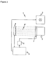
- FIG. 2 illustrates a second embodiment of the invention utilizing a direct internal additional light source
- FIG. 3 illustrates a third embodiment of the invention which includes modification of light from the externally emitting light source.
- FIG. 1 illustrates a first embodiment of an optoelectronic monitoring device 1 constructed in accordance with the present invention.
- Light from a light source 2 illuminates a scenery (in the drawing, the right side of the drawing sheet).
- Light returned from the scenery is directed to a picture sensor 4 via a focusing optics 3 .
- Monitoring device 1 serves to recognize objects in a monitoring zone of the scenery.
- Such recognitions have a multitude of uses ranging from automation to burglary prevention.
- the recognized objects can be counted, their movement can be determined, or their presence can be classified as a permitted or prohibited presence in the monitored zone. If an object is a prohibited object, a warning signal can be generated. This is useful for safety purposes to secure, for example, a dangerous area into which no objects may enter, or to timely deactivate a dangerous machine when an object nevertheless enters a prohibited zone.
- monitoring device 1 is well-known and often utilized, the present application does not further describe details of the tubular member or the precise selection of apertures and lenses of the focusing optics 3 . It is only important that following a reflection at the scenery, sufficient light from light source 2 is focused onto picture sensor 4 to enable a distance determination.
- Light source 2 can be a laser diode, and its reflected light beam strikes a single photo cell of picture sensor 4 .
- picture sensor 4 has a multitude of receiving units arranged along a line or in a two-dimensional matrix or which are otherwise arranged in a way appropriate to the particular application.
- Picture sensor 4 can for example be a CCD chip or a CMOS chip.
- Picture sensor 4 communicates with a control unit 5 .
- Control unit 5 is further coupled to light source 2 for controlling the generation of a desired illumination pattern.
- each receiving element of picture sensor 4 has its own evaluation unit.
- evaluation units are used to determine the distance of the viewed area, and they forward to the control unit 5 only the finalized distance data. They can typically also be used to determine the light intensity, which is not further considered herein.
- the receiving elements only communicate the raw data, which is then further processed by control unit 5 .
- the present application describes the invention as if it were associated with receiving elements that themselves determine the distances.
- the distance determination takes place in accordance with the present invention in one of two ways, although both approaches could also be implemented together.
- light source 2 emits a light pulse and its elapsed time is determined by picture sensor 4 . Due to the short time intervals involved here, very precise electronics are required. Since the distances relevant to the present invention have an order of magnitude of about 10 meters, the elapsed time for such a distance is about 33 ns. In addition, fractions thereof should be determinable so that object movements of an order of magnitude of a few centimeters can be detected. To convert running time to absolute distance data, the monitoring device must first be calibrated.
- an electro-optical shutter can be used to simulate a defined exterior running time.
- relative distances can be used to determine, for example, how the relative distances differ for two successive distance pictures or for a single distance picture and a reference picture.
- light source 2 emits modulated light, that is, light onto which an additional period is superimposed, for example by sinusoidally modulating the brightness of the light.
- the distance can be calculated from the phase difference between the modulated light at light source 2 and at picture sensor 4 . Any ambiguity resulting from a phase shift by whole multiples is immaterial if the elapsed light running time in one period approximately corresponds to the observed distances or distance differences.
- a constant distance sensed by a receiving element can be caused by a motionless scenery or by an error or deficiency of the receiving element.
- a modifying device 6 is provided that is addressed by control unit 5 .
- the modifying device 6 in turn controls an additional light source 7 .
- modifying device 6 generates a light pulse at a precise point in time or modulated light of a predetermined phase.
- the additional light source is configured so that light receiver 4 functions in its optimal operating range and is not driven to its saturation point. It employs typical signal values as are encountered when detecting objects in normal use.
- a beam splitter 7 ′ diverts light from additional light source 7 onto picture sensor 4 . There is therefore a light path 8 of external light from the scenery which is transmitted through beam splitter 7 ′ and a light path 8 ′ from the additional light source 7 that is reflected by beam splitter 7 ′.
- control unit 5 illuminates picture sensor 4 with a precisely timed light pulse or with light of a predetermined phase via modifying device 6 , additional light source 7 and beam splitter 7 ′.
- the receiving elements of picture sensor 4 are functionally tested as follows.
- control unit 5 To determine the distance on the basis of the elapsed time, control unit 5 initially turns off light source 2 since its light can interfere with the functional test. This can be avoided when light from additional light source 7 has an intensity sufficient to overpower the light reflected by the scenery.
- control unit 5 directs a start signal to picture sensor 4 as if light source 2 had emitted a light pulse. Outside the testing operation, an actual command to generate such a light pulse would be sent to light source 2 . For the functionality test, such a command to light source 2 is omitted.
- Control unit 5 sends a command with a predetermined time delay via modifying device 6 to the additional light source to emit a light pulse.
- This light pulse reaches picture sensor 4 with the known delay as compared to the start signal sent via beam splitter 7 ′ and along light path 8 ′. From this, the receiving elements of picture sensor 4 determine the distance, which is of course fictitious because no light is received from the scenery.
- Control unit 5 receives the calculated distances and compares them with those that are expected for the predetermined and therefore known time delay. If there are deviations, an error or malfunctioning of the corresponding receiving unit is assumed.
- the delays can be varied to simulate for picture sensor 4 different distances within the overall measurement range.
- a zero delay represents a special case because it does not involve an artificial delay.
- the distance that is to be determined is the length of optical path 8 ′.
- the control unit 5 can perform the function of modifying device 6 by activating the additional light source. This greatly simplifies the device and control effort for the test.
- the test is similar.
- modulated light with a predetermined phase shift instead of a delayed light pulse is used.
- the receiving elements calculate the distance from this artificial phase, and the result is compared with the expected results for the predetermined artificial phase.
- the artificial phase can be varied to test across the entire measurement range of picture sensor 4 .
- the exceptional case of a zero phase should be mentioned, which involves no additional phase shift, so that the result is the length of optical path 8 ′ if the monitoring device 1 is operative.
- a measurement error can be recognized with the distances resulting from the test since the length of optical path 8 ′ and the fictitious additional length due to the delay are known.
- the testing can include a comparison of the measurement error with a required measurement accuracy.
- the required measurement accuracy can be stored as a fixed threshold value in control unit 5 .
- the threshold value or values for each instrument can be stored ahead of time, for example during its production.
- the threshold values are more precise when, due to the temperature dependency of the accuracy of the light receiver 4 , they are determined on the basis of this temperature dependency and are stored as such.
- the appropriate threshold value can be selected from the resulting stored, temperature dependent graph or diagram by measuring the actual operating temperature during the test with a temperature sensor.
- light source 2 can take over the function of additional light source 7 by directing light from the former to light receiver 4 . It is also possible to place the additional light source as a further element adjacent light source 2 outside the monitoring device. With this alternative, the light can be combined directly or through focusing optics 3 .
- Monitoring device 1 is typically mounted in a housing, and light enters and exits the housing through a light-transmitting frontal or protective shield. Due to the external positioning of light sources 2 , 7 , the light transmissivity of the protective shield can be checked to detect any damage or contamination thereof. The protective shield also dampens the intensity of the combined light to help prevent an oversaturation of the light receivers.
- the optical capacity of light sources 2 , 7 or their equivalent on light receiver 4 can be evaluated in control unit 5 to check its sensitivity. For one, this serves to check the light transmissivity of the protective shield as mentioned above. In addition, the range over which objects can be detected depends on this sensitivity. Should the sensitivity drop below a predetermined operative range of monitoring device 1 , an error or malfunction can be detected.
- Light sources 2 , 7 can be positioned approximately at the focal distance of focusing optics 3 . Light receivers 2 are then fully illuminated so that especially in the case of a CCD or a CMOS matrix, all pixels can be checked.
- FIG. 2 shows a second embodiment of the invention.
- the additional light is sent directly to picture sensor 4 instead of via the beam splitter 7 ′.
- the additional light source 7 lies in the optical path of the reflected light from the scenery, as can be seen in FIG. 2 , and would therefore cover that path, the additional light source 7 is geometrically shaped so that it does not disturb optical path 8 .
- this is attained by giving the additional light source 7 a ring-shaped or annular configuration arranged about focusing optics 3 , so that it can readily direct light along path 8 ′′ to picture sensor 4 .
- Other geometric forms, such as a rectangular shape or another mounting configuration, can of course be used so long as they do not excessively interfere with the optical path 8 .
- the additional light source 7 can be constructed of several parts so that for a given picture or test run different ranges of picture sensor 4 , and therewith different receiving elements, can be tested by faking different distances.
- the functional test according to the first and second embodiments is independent of the referenced scenery due to the internal additional light source, which makes it particularly well adapted for mobile installations.
- FIG. 3 shows a third embodiment of the invention. This embodiment does not have an additional light source 7 and instead modifies the light from light source 2 . Modifying device 6 is therefore placed between light source 2 and control unit 5 .
- Control unit 5 sends a command to modifying device 6 that the monitoring device is not operating normally and that a test will follow. It then issues an activation command via modifying device 6 to light source 2 and simultaneously therewith a synchronization signal to picture sensor 4 .
- the modifying device delays the light pulse by a predetermined amount. If the distance measurement is performed with modulated light, the phase is shifted by a predetermined amount.
- the light from light source 2 is reflected by the scenery and reaches the receiving elements of picture sensor 4 via exit path 9 , reflection path 9 ′, focusing optics 3 and the optical path 8 . They are not aware that a test is in progress and that the light has been modified and calculate the distance in the normal manner. The distance data is then forwarded to control unit 5 .
- Control unit 5 compares whether the distance picture is plausible. This requires that the distance data differs within a narrow tolerance range from that of a reference picture taken just prior to or after the test and by the amount faked or feinted by modifying device 6 , or that was previously stored. Data from previously processed pictures can also be used as test data. This includes, for example, data from previously detected objects, background surfaces or the like which need not necessarily be compared in the plane of the individual pixels. Receiving units which do not detect the expected deviation must initially be considered to be defective and will need further, more comprehensive testing.
- the scenery is made dynamic by appropriate manipulation so that an earlier defined and therewith correctable artificial measurement error is generated. Since the functional test in accordance with the third embodiment is based on reflected light, it is less well adapted for mobile monitoring devices 1 such as, for example, a movable robot or a vehicle. It must be assured that sufficient light is reflected by the background scene. However, the additional light source 7 can be omitted, and the entire signal path can be tested instead of only the internal path as in the other embodiments.
- the disclosed tests can be used with distance measuring sensors in one-, two- and three-dimensional monitoring systems.
- the functional test can be expanded by including test cycles for a darkness test in which light is not combined and the scenery is not changed. With the dark noise, certain pixel errors such as burn-ins (stuck at low/stuck at high) can be found. With the earlier-described temperature graph, the expected background measurement can be determined at the measured temperature and compared with the actual dark noise. In several respects, this test is redundant but provides a relatively secure manner of detecting at least rougher failed functions.
Landscapes
- Physics & Mathematics (AREA)
- General Physics & Mathematics (AREA)
- Engineering & Computer Science (AREA)
- Computer Networks & Wireless Communication (AREA)
- Radar, Positioning & Navigation (AREA)
- Remote Sensing (AREA)
- Life Sciences & Earth Sciences (AREA)
- General Life Sciences & Earth Sciences (AREA)
- Geophysics (AREA)
- Electromagnetism (AREA)
- Optical Radar Systems And Details Thereof (AREA)
- Measurement Of Optical Distance (AREA)
Applications Claiming Priority (6)
| Application Number | Priority Date | Filing Date | Title |
|---|---|---|---|
| DE102006050768.1 | 2006-10-27 | ||
| DE102006050768 | 2006-10-27 | ||
| DE102006050768 | 2006-10-27 | ||
| DE102007008806.1 | 2007-02-22 | ||
| DE102007008806A DE102007008806C5 (de) | 2006-10-27 | 2007-02-22 | Optoelektronische Überwachung mit Test durch Dynamisierung |
| DE102007008806 | 2007-02-22 |
Publications (2)
| Publication Number | Publication Date |
|---|---|
| US20080106724A1 US20080106724A1 (en) | 2008-05-08 |
| US7710548B2 true US7710548B2 (en) | 2010-05-04 |
Family
ID=38885280
Family Applications (1)
| Application Number | Title | Priority Date | Filing Date |
|---|---|---|---|
| US11/977,176 Active 2028-08-04 US7710548B2 (en) | 2006-10-27 | 2007-10-22 | Optoelectronic monitor including dynamic testing unit |
Country Status (4)
| Country | Link |
|---|---|
| US (1) | US7710548B2 (de) |
| DE (1) | DE102007008806C5 (de) |
| FR (1) | FR2907949A1 (de) |
| IT (1) | ITMI20071931A1 (de) |
Cited By (1)
| Publication number | Priority date | Publication date | Assignee | Title |
|---|---|---|---|---|
| US11506768B2 (en) * | 2018-02-20 | 2022-11-22 | Espros Photonics Ag | TOF camera device for error detection |
Families Citing this family (21)
| Publication number | Priority date | Publication date | Assignee | Title |
|---|---|---|---|---|
| DE102007038013B4 (de) * | 2007-08-10 | 2009-06-25 | Fraba Ag | Verfahren zur optischen Messung von Geschwindigkeiten und Sensor zur optischen Messung von Geschwindigkeiten |
| US8872113B2 (en) * | 2012-02-21 | 2014-10-28 | Rockwell Automation Technologies, Inc. | System to test performance of pixels in a sensor array |
| US9083946B2 (en) * | 2012-02-21 | 2015-07-14 | Rockwell Automation Technologies, Inc. | System to detect failed pixels in a sensor array |
| JP6190690B2 (ja) * | 2013-10-21 | 2017-08-30 | 本田技研工業株式会社 | 距離測定システム及び補正用データの取得方法 |
| JP6230444B2 (ja) * | 2014-02-21 | 2017-11-15 | オムロンオートモーティブエレクトロニクス株式会社 | レーザレーダ装置 |
| DE102016106417B3 (de) * | 2016-04-08 | 2017-05-11 | Sick Ag | Optoelektronischer Sensor mit einem Messdatenspeicher und Speichertestverfahren |
| RU167849U1 (ru) * | 2016-07-11 | 2017-01-20 | Акционерное общество "Научно-исследовательский институт оптико-электронного приборостроения" АО "НИИ ОЭП" | Устройство функционального контроля сквозного тракта оптико-электронного прибора с многоэлементным приемником излучения |
| US10359507B2 (en) * | 2016-12-30 | 2019-07-23 | Panosense Inc. | Lidar sensor assembly calibration based on reference surface |
| US10451741B2 (en) | 2017-04-30 | 2019-10-22 | Microsoft Technology Licensing, Llc | Time of flight camera |
| US10989605B2 (en) * | 2017-10-26 | 2021-04-27 | Arete Associates | Streak camera calibration |
| EP3508874A1 (de) * | 2018-01-03 | 2019-07-10 | Espros Photonics AG | Kalibriervorrichtung für eine tof-kameravorrichtung |
| DE102018116481B3 (de) | 2018-07-06 | 2019-10-24 | Sick Ag | 3D-Lichtlaufzeitkamera und Verfahren zur Erfassung dreidimensionaler Bilddaten |
| DE102018119435A1 (de) * | 2018-08-09 | 2020-02-13 | Huf Hülsbeck & Fürst Gmbh & Co. Kg | Verfahren zur Kalibrierung einer Time-Of-Flight-Kamera |
| DE102019115792B4 (de) | 2019-06-11 | 2024-05-02 | Sick Ag | Triangulationslichttaster |
| WO2021001903A1 (ja) * | 2019-07-01 | 2021-01-07 | 三菱電機ビルテクノサービス株式会社 | 状態判定装置、エレベーターシステム、ホームシステム、およびビルシステム |
| US11460562B2 (en) | 2019-07-09 | 2022-10-04 | Siemens Industry Software Netherlands B.V. | Methods to simulate continuous wave lidar sensors |
| CN116134335A (zh) * | 2020-07-21 | 2023-05-16 | 株式会社电装 | 物体检测装置及检测物体检测装置的故障的方法 |
| EP3995852A1 (de) | 2020-11-06 | 2022-05-11 | Sick Ag | Abstandsmessung eines objekts |
| EP4047389B1 (de) | 2021-02-18 | 2023-03-29 | Sick Ag | Erfassung dreidimensionaler bilddaten |
| DE102021117818A1 (de) | 2021-07-09 | 2023-01-12 | Sick Ag | Kamera zur Erfassung dreidimensionaler Bilddaten und Verfahren zur Überprüfung der Funktionsfähigkeit einer Kamera |
| CN117092626B (zh) * | 2023-10-20 | 2023-12-15 | 成都量芯集成科技有限公司 | 一种激光测距光机调试生产装置及其实现方法 |
Citations (10)
| Publication number | Priority date | Publication date | Assignee | Title |
|---|---|---|---|---|
| US4699508A (en) * | 1981-06-09 | 1987-10-13 | Mtc Messtechnik Und Optelektronik Ag | Method of measuring the distance of a target and apparatus for its performance |
| US5082364A (en) * | 1990-08-31 | 1992-01-21 | Russell James T | Rf modulated optical beam distance measuring system and method |
| US20010013929A1 (en) * | 2000-02-14 | 2001-08-16 | Gogolla Torsten | Method and device for optoelectronic distance measurement |
| DE10138960A1 (de) | 2001-08-03 | 2003-02-27 | Pilz Gmbh & Co | Verfahren und Vorrichtung zum Beobachten, Vermessen oder Überwachen eines Raumbereichs |
| DE10021590C2 (de) | 1999-05-08 | 2003-04-17 | Leuze Electronic Gmbh & Co | Optoelektronische Vorrichtung |
| DE10360174A1 (de) | 2003-12-20 | 2005-07-21 | Leuze Lumiflex Gmbh + Co. Kg | Vorrichtung zur Überwachung eines Erfassungsbereichs an einem Arbeitsmittel |
| DE10360789A1 (de) | 2003-12-23 | 2005-07-28 | Leuze Lumiflex Gmbh + Co. Kg | Vorrichtung zur Überwachung eines Erfassungsbereichs an einem Arbeitsmittel |
| DE102004035243A1 (de) | 2004-07-21 | 2006-02-16 | Sick Ag | Kameraanordnung |
| US20070076189A1 (en) * | 2005-09-30 | 2007-04-05 | Kabushiki Kaisha Topcon | Distance measuring device |
| US7310109B2 (en) * | 2000-04-07 | 2007-12-18 | Pilz Gmbh & Co. | Protective device for safeguarding a hazardous area and method of checking the functional reliability of such a device |
-
2007
- 2007-02-22 DE DE102007008806A patent/DE102007008806C5/de active Active
- 2007-10-05 IT IT001931A patent/ITMI20071931A1/it unknown
- 2007-10-22 US US11/977,176 patent/US7710548B2/en active Active
- 2007-10-26 FR FR0758633A patent/FR2907949A1/fr not_active Withdrawn
Patent Citations (12)
| Publication number | Priority date | Publication date | Assignee | Title |
|---|---|---|---|---|
| US4699508A (en) * | 1981-06-09 | 1987-10-13 | Mtc Messtechnik Und Optelektronik Ag | Method of measuring the distance of a target and apparatus for its performance |
| US5082364A (en) * | 1990-08-31 | 1992-01-21 | Russell James T | Rf modulated optical beam distance measuring system and method |
| DE10021590C2 (de) | 1999-05-08 | 2003-04-17 | Leuze Electronic Gmbh & Co | Optoelektronische Vorrichtung |
| US20010013929A1 (en) * | 2000-02-14 | 2001-08-16 | Gogolla Torsten | Method and device for optoelectronic distance measurement |
| US7310109B2 (en) * | 2000-04-07 | 2007-12-18 | Pilz Gmbh & Co. | Protective device for safeguarding a hazardous area and method of checking the functional reliability of such a device |
| DE10138960A1 (de) | 2001-08-03 | 2003-02-27 | Pilz Gmbh & Co | Verfahren und Vorrichtung zum Beobachten, Vermessen oder Überwachen eines Raumbereichs |
| DE10360174A1 (de) | 2003-12-20 | 2005-07-21 | Leuze Lumiflex Gmbh + Co. Kg | Vorrichtung zur Überwachung eines Erfassungsbereichs an einem Arbeitsmittel |
| US20050207619A1 (en) | 2003-12-20 | 2005-09-22 | Leuze Lumiflex Gmbh & Co., Kg | Device for monitoring an area of coverage on a work tool |
| DE10360789A1 (de) | 2003-12-23 | 2005-07-28 | Leuze Lumiflex Gmbh + Co. Kg | Vorrichtung zur Überwachung eines Erfassungsbereichs an einem Arbeitsmittel |
| US20050265596A1 (en) | 2003-12-23 | 2005-12-01 | Lutz Lohmann | Device for monitoring an area of coverage on a work tool |
| DE102004035243A1 (de) | 2004-07-21 | 2006-02-16 | Sick Ag | Kameraanordnung |
| US20070076189A1 (en) * | 2005-09-30 | 2007-04-05 | Kabushiki Kaisha Topcon | Distance measuring device |
Cited By (1)
| Publication number | Priority date | Publication date | Assignee | Title |
|---|---|---|---|---|
| US11506768B2 (en) * | 2018-02-20 | 2022-11-22 | Espros Photonics Ag | TOF camera device for error detection |
Also Published As
| Publication number | Publication date |
|---|---|
| FR2907949A1 (fr) | 2008-05-02 |
| ITMI20071931A1 (it) | 2008-04-28 |
| DE102007008806C5 (de) | 2010-05-06 |
| US20080106724A1 (en) | 2008-05-08 |
| DE102007008806B3 (de) | 2008-02-07 |
Similar Documents
| Publication | Publication Date | Title |
|---|---|---|
| US7710548B2 (en) | Optoelectronic monitor including dynamic testing unit | |
| US7995836B2 (en) | Optoelectronic multiplane sensor and method for monitoring objects | |
| KR101891907B1 (ko) | 거리 측정 장치 및 시차 연산 시스템 | |
| US10031228B2 (en) | Object detecting apparatus | |
| JP2009516157A (ja) | 空間領域モニター装置および方法 | |
| CN103975250A (zh) | 在图像平面中利用动态掩模的空间选择性探测 | |
| US20230003524A1 (en) | Automatic locating of target marks | |
| EP2632166B1 (de) | System zur Prüfung der Leistung von Pixeln in einem Sensorarray | |
| CN107957237A (zh) | 具有闪光对准的激光投影仪 | |
| JP2007514144A (ja) | 近接度検出器 | |
| US10864679B2 (en) | Method of manufacturing an optoelectronic sensor | |
| EP3974770A1 (de) | Verbesserte zeigewinkelvalidierung | |
| JP6186863B2 (ja) | 測距装置及びプログラム | |
| US11353551B2 (en) | Simulation device for monitoring a motor vehicle | |
| JP2020177012A (ja) | 光学装置、車載システム、および移動装置 | |
| JP2004074898A (ja) | 進入角指示灯の監視装置 | |
| US20160297031A1 (en) | Method for Producing a Laser Weld Seam Between Components by Use of a Spherical or Sphere-Like Element, and Corresponding Component Connection | |
| US20230305159A1 (en) | Apparatus for testing lidar modules and test method | |
| JP7483548B2 (ja) | 電磁波検出装置 | |
| US20240067094A1 (en) | Gating camera, vehicle sensing system, and vehicle lamp | |
| JPH03190418A (ja) | レーザ式光電スイッチおよび測距装置 | |
| CN114859318A (zh) | 具有射束光学诊断的激光雷达系统 | |
| JP2007057424A (ja) | 測距センサの検査装置及び検査方法 | |
| JP2004274708A (ja) | 画像記録の起動 | |
| JPS62222117A (ja) | 多点距離計測センサ |
Legal Events
| Date | Code | Title | Description |
|---|---|---|---|
| AS | Assignment |
Owner name: SICK AG, GERMANY Free format text: ASSIGNMENT OF ASSIGNORS INTEREST;ASSIGNORS:BRAUNE, INGOLF;WUESTEFELD, MARTIN;REEL/FRAME:021774/0733;SIGNING DATES FROM 20071023 TO 20071024 Owner name: SICK AG,GERMANY Free format text: ASSIGNMENT OF ASSIGNORS INTEREST;ASSIGNORS:BRAUNE, INGOLF;WUESTEFELD, MARTIN;SIGNING DATES FROM 20071023 TO 20071024;REEL/FRAME:021774/0733 |
|
| STCF | Information on status: patent grant |
Free format text: PATENTED CASE |
|
| FPAY | Fee payment |
Year of fee payment: 4 |
|
| MAFP | Maintenance fee payment |
Free format text: PAYMENT OF MAINTENANCE FEE, 8TH YEAR, LARGE ENTITY (ORIGINAL EVENT CODE: M1552) Year of fee payment: 8 |
|
| MAFP | Maintenance fee payment |
Free format text: PAYMENT OF MAINTENANCE FEE, 12TH YEAR, LARGE ENTITY (ORIGINAL EVENT CODE: M1553); ENTITY STATUS OF PATENT OWNER: LARGE ENTITY Year of fee payment: 12 |