US7609072B2 - Processing tantalum capacitors on assembled PWAs to yield low failure rate - Google Patents
Processing tantalum capacitors on assembled PWAs to yield low failure rate Download PDFInfo
- Publication number
- US7609072B2 US7609072B2 US11/730,995 US73099507A US7609072B2 US 7609072 B2 US7609072 B2 US 7609072B2 US 73099507 A US73099507 A US 73099507A US 7609072 B2 US7609072 B2 US 7609072B2
- Authority
- US
- United States
- Prior art keywords
- capacitor
- predetermined
- time
- voltage
- leakage current
- Prior art date
- Legal status (The legal status is an assumption and is not a legal conclusion. Google has not performed a legal analysis and makes no representation as to the accuracy of the status listed.)
- Expired - Fee Related, expires
Links
- 239000003990 capacitor Substances 0.000 title claims abstract description 152
- 229910052715 tantalum Inorganic materials 0.000 title claims abstract description 57
- GUVRBAGPIYLISA-UHFFFAOYSA-N tantalum atom Chemical compound [Ta] GUVRBAGPIYLISA-UHFFFAOYSA-N 0.000 title claims abstract description 57
- 238000000034 method Methods 0.000 claims abstract description 43
- 230000003750 conditioning effect Effects 0.000 claims abstract description 28
- 230000032683 aging Effects 0.000 claims abstract description 9
- 238000005259 measurement Methods 0.000 claims description 20
- 238000012216 screening Methods 0.000 claims description 9
- 230000003247 decreasing effect Effects 0.000 claims description 6
- 230000002431 foraging effect Effects 0.000 claims 1
- 238000012360 testing method Methods 0.000 abstract description 43
- 230000000712 assembly Effects 0.000 abstract description 8
- 238000000429 assembly Methods 0.000 abstract description 8
- AHCYMLUZIRLXAA-SHYZEUOFSA-N Deoxyuridine 5'-triphosphate Chemical compound O1[C@H](COP(O)(=O)OP(O)(=O)OP(O)(O)=O)[C@@H](O)C[C@@H]1N1C(=O)NC(=O)C=C1 AHCYMLUZIRLXAA-SHYZEUOFSA-N 0.000 description 29
- 238000004519 manufacturing process Methods 0.000 description 8
- 238000013461 design Methods 0.000 description 3
- 230000000977 initiatory effect Effects 0.000 description 3
- 230000001143 conditioned effect Effects 0.000 description 2
- 238000013459 approach Methods 0.000 description 1
- 239000003985 ceramic capacitor Substances 0.000 description 1
- 238000001514 detection method Methods 0.000 description 1
- 230000005669 field effect Effects 0.000 description 1
- 238000012986 modification Methods 0.000 description 1
- 230000004048 modification Effects 0.000 description 1
- 239000000843 powder Substances 0.000 description 1
Images


Classifications
-
- G—PHYSICS
- G01—MEASURING; TESTING
- G01R—MEASURING ELECTRIC VARIABLES; MEASURING MAGNETIC VARIABLES
- G01R31/00—Arrangements for testing electric properties; Arrangements for locating electric faults; Arrangements for electrical testing characterised by what is being tested not provided for elsewhere
- G01R31/01—Subjecting similar articles in turn to test, e.g. "go/no-go" tests in mass production; Testing objects at points as they pass through a testing station
- G01R31/013—Testing passive components
- G01R31/016—Testing of capacitors
Definitions
- the present invention relates to reducing electronic component failures, and more particularly, to a method of conditioning tantalum capacitors to yield low failure rates, while avoiding severe failures for such components when used at full ratings.
- tantalum capacitors exhibit a high failure rate, where the tantalum capacitors were used as an energy reservoir to supply controlled pulses of current to a load.
- Production failures can occur at system level testing, where a failure can prove to be quite costly, with a loss of production, and significant man-hours lost to repair and replace costly system parts.
- Failure modes of interest for tantalum capacitors are low impedance paths, or even short circuits, between the capacitor's anode and cathode.
- the root-cause of the tantalum capacitor failures was found to be the initial application of voltage and/or pulsed current supplied to and from the capacitors.
- tantalum capacitor failure modes and the root cause of such failures are well known, the high failure rates associated with these components appear to be accepted in OEM industry.
- the trend in manufacturing has been the use of finer powders to make tantalum capacitors, driven by a demand for smaller components.
- industry's response has been to de-rate capacitors.
- early Mil Spec standards de-rated capacitor voltages by 70%; more recently, however, the de-rating level has been more typically at 50%. See MIL-HDBK-217F Notice 2, which can be found at www.weibull.com/knowledge/milhdbk.htm.
- the present invention is a method of reducing the failure rate of tantalum capacitors, and, in particular, when used in circuit assemblies, such as power supply printed wiring assemblies, by detecting failures of the tantalum capacitors before the circuit assembly is placed in a system to avoid detection of the failure at system level.
- each of the capacitors in a circuit assembly is subjected to the same conditioning level during testing by conducting the testing with the capacitors mounted in the circuit assembly.
- surge currents are induced in the capacitors in a controlled manner as a means of “aging” the components to thereby produce tantalum capacitors that can be used without de-rating at low failure rates.
- the level of voltage, timing and current levels are set by the circuitry of the test.
- the same circuit assemblies that are used in a system application are also used for the tantalum capacitor test circuit during the conditioning process.
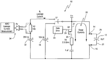
- FIG. 1 is an example of a “burn-in” tester for performing tantalum capacitor conditioning and screening.
- FIG. 2 shows several waveform sketches for the timing and levels of voltage pulses used to induce surge currents in tantalum capacitors being conditioned and screened.
- FIG. 3 is a drawing showing leakage current measurements by tantalum capacitors conditioned and screened using the “burn-in” tester shown in FIG. 1 .
- the present invention is a method of reducing the failure rate of tantalum capacitors used in circuit assemblies by conditioning the capacitors in a “burn-in” tester for the purpose of screening the capacitors by detecting failures of the capacitors before the circuit assembly is placed in a system to thereby avoid failures at system level.
- the method of the present invention will be explained in terms of the tantalum capacitors used in a power supply module used as a subsystem in a system where high reliability is required. It should be understood, however, that the method is not limited to conditioning and screening tantalum capacitors used in a power supply assembly.
- tantalum capacitors there can be multiple tantalum capacitors on a power supply assembly circuit card. Each of these capacitors is subjected to the same conditioning level during testing. Conditioning and testing of the tantalum capacitors is performed with the capacitors mounted on an assembled printed wire assembly.
- FIG. 2 describes the timing and levels of the voltage pulses and resulting current surges used in this process.
- FIG. 1 shows a burn-in test circuit 10 , that is based on power supply circuitry, and that is used to perform tantalum capacitor test and conditioning. It should be noted, however, that although the present invention is described in connection with power supply circuitry used for conditioning tantalum capacitors, the method of the present invention could practiced with other types of printed wire assemblies by directly probing the capacitors in such other assemblies and using, for example, the circuitry shown in FIG. 1 to test the capacitors. In that instance, the circuitry shown for example in FIG. 1 would be external to the printed wire assembly including the capacitors under test.
- the first part of the tantalum capacitor screening involves subjecting a tantalum capacitor 12 to be tested to pulsed surge current conditioning.
- the tantalum capacitor 12 to be tested which is typically referred to as the device under test (“DUT”)
- DUT device under test
- the pulsed surge current conditioning a voltage of +15VDC from a DC voltage supply 18 , is first applied to DUT 12 through a switch S 1 .
- a power pulsing circuit 20 applies several series of voltages pulses 22 to the gate 24 of a Field Effect Transistor (FET) Q 1 to produce the DUT surge currents 26 shown in FIG. 2 .
- FET Field Effect Transistor
- the number of pulse periods, or their duration in time, or the frequency or duty cycle of the pulses may be changed according to the size or voltage rating of the capacitor under test or to obtain leakage criteria, or yield, or a particular test time.
- the time for Pulse Period 1 extends from the start of the test, i.e., from 0 seconds to 60 seconds after the start of the test.
- a series of voltage pulses 28 occurring at a frequency of preferably 12 kHz and having an on time of preferably 25%, are applied to gate 24 of FET Q 1 .
- the resultant switching of FET Q 1 produces a series of corresponding voltage pulses occurring at the source 21 of FET Q 1 and at the anode 25 of tantalum capacitor DUT 12 , resulting in the production of surge currents 30 through DUT 12 and FET Q 1 at a corresponding rate of 12 kHz, with a 50% Duty Cycle for a period of 15 seconds over the 60 seconds constituting Pulse Period 1 .
- the peak surge current level through DUT 12 is approximately 5 Amps.
- a small resistor R 1 is connected in series with the drain of FET Q 1 to limit the amount of current flowing through it.
- resistor R 1 has a value of 3.3 ⁇ .
- a waiting period of 45 seconds is allowed to lapse before the initiation of Pulse Period 2 , also shown in FIG. 2 .
- the time for Pulse Period 2 extends from 60 seconds after the start of the test to 120 seconds after the start of the test.
- a second series of voltage pulses 28 occurring again at a frequency of preferably 12 kHz and having an on time of preferably 25%, are applied to gate 24 of FET Q 1 .
- the resultant switching of FET Q 1 again produces a series of corresponding voltage pulses occurring at the source 21 of FET Q 1 and at the anode 25 of tantalum capacitor DUT 12 , resulting in the production of surge currents 30 through DUT 12 and FET Q 1 , again at a corresponding rate of 12 kHz, with a 50% Duty Cycle for a period of 15 seconds over the 60 seconds constituting Pulse Period 2 .
- the peak surge current level through DUT 12 is again approximately 5 Amps.
- a waiting period of 45 seconds is allowed to lapse before the initiation of Pulse Period 3 shown in FIG. 2 .
- the time for Pulse Period 3 extends from 120 seconds after the start of the test to 180 seconds after the start of the test.
- a third series of voltage pulses 28 occurring once more at a frequency of preferably 12 kHz and having an on time of preferably 25%, are applied to gate 24 of FET Q 1 .
- the resultant switching of FET Q 1 once more produces a series of corresponding voltage pulses occurring at the source 21 of FET Q 1 and at the anode 25 of tantalum capacitor DUT 12 , resulting again in the production of surge currents 30 through DUT 12 and FET Q 1 , again at a corresponding rate of 12 kHz, with a 50% Duty Cycle for a period of 15 seconds over the 60 seconds constituting Pulse Period 3 .
- the peak surge current level through DUT 12 is approximately 5 Amps, and again, to provide thermal relief to circuit 10 , a waiting period of 45 seconds is allowed to lapse before the initiation of next part of the capacitor testing shown in FIG. 2 .
- the next part of the capacitor screening test process involves subjecting DUT 12 to leakage current measurements for purposes of grading DUT 12 .
- the leakage current test is initiated at the end of Pulse Period 3 , i.e., at 180 seconds, at which point, a DC voltage of 35VDC is applied to DUT 12 through switch S 1 from a second DC voltage supply 32 .
- Gate Drive circuit 20 does not apply voltages pulses 22 to the gate 24 of a FET Q 1 , such that FET Q 1 is not conducting.
- the DC voltage of 35VDC is applied to DUT 12 for a period of preferably 60 seconds.
- a time equal to 240 seconds leakage current measurements for DUT 12 are begun.
- the leakage current measurements are done preferably twice over the entire interval of 80 seconds beginning at a time of 180 seconds and ending at a time of 270 seconds.
- the leakage current level through DUT 12 is measured at least two times (minimum) over this entire interval, with measurements being recorded preferably first at 240 seconds and then again at 270 seconds.
- the leakage current test measurements are taken by measuring the voltage across a known value resistor R 2 that is connected in series with DUT 12 .
- resistor R 2 has a value of 10 k ⁇ .
- the voltage measurement is taken using a meter 34 shown in FIG. 1 .
- DUT 12 is then graded on the basis of the results of the leakage current measurements taken for DUT 12 .
- Tantalum capacitor DUT 12 is considered to have a passing grade where (1) DUT 12 has a level of leakage current that is decreasing over time, based on the measurements taken at 240 seconds and 270 seconds; or (2) DUT 12 has a level of leakage current that is less than 2 uA at 270 seconds.
- Tantalum Capacitor DUT 12 is considered to have a failing grade where (1) DUT 12 has a level of leakage current that is increasing over time, based on the measurements taken at 240 seconds and 270 seconds; or (2) DUT 12 has a level of leakage current that is greater than 2 uA at 270 seconds.
- a failing grade result where DUT 12 has a level of leakage current that is increasing over time is reflected in curve 42 shown in FIG. 3 .
- a failing grade result where DUT 12 has a level of leakage current that is greater than 2 uA at 270 seconds is reflected in curve 44 shown in FIG. 3 .
- a failed DUT can be retested (i.e., subjected to a second conditioning) or discarded. Previous data indicates that (1) most capacitors will pass the conditioning test after a second test is performed; and (2) capacitors that fail a second test will never pass with a level of leakage current that is less than 2 uA.
- the failure rate for the tantalum capacitors was found to be 2-5%.
- the failure rate of the capacitors was found to be higher at the printed wire assembly burn-in level, compared to that previously found at the system burn-in level. This suggests that the power supply tantalum capacitor conditioning process is more stressful than the actual application in which the tantalum capacitors are used, which offers a margin during the screen process.
- the conditioning process for tantalum capacitors can be used with any printed wire assemblies using tantalum capacitors.
- the process can be extended to the discrete component level to produce high reliability tantalum capacitors for printed wire assembly applications.
- the process can be used on both leaded and SMT components.
- the process of the present invention when used at the discrete component level, can produce a high quality, high capacitance device that can be used in applications that typically call for high capacitance ceramic capacitors, which typically cost 10-30 times the cost of tantalum capacitors, based on a per micro-farad basis.
- One possible conditioner and tester application includes Switched Mode Power Supplies.
Landscapes
- Engineering & Computer Science (AREA)
- Power Engineering (AREA)
- Physics & Mathematics (AREA)
- General Physics & Mathematics (AREA)
- Testing Electric Properties And Detecting Electric Faults (AREA)
- Fixed Capacitors And Capacitor Manufacturing Machines (AREA)
Priority Applications (4)
| Application Number | Priority Date | Filing Date | Title |
|---|---|---|---|
| US11/730,995 US7609072B2 (en) | 2007-04-05 | 2007-04-05 | Processing tantalum capacitors on assembled PWAs to yield low failure rate |
| JP2008096671A JP2008256695A (ja) | 2007-04-05 | 2008-04-03 | 欠陥率を低くするための組み立てられたpwa上のタンタルコンデンサの処理 |
| DE602008002087T DE602008002087D1 (de) | 2007-04-05 | 2008-04-03 | Verarbeitung von Tantal-Kondensatoren auf montierten PWAs zur Erreichung einer niedrigen Fehlerrate |
| EP08154016A EP1978370B1 (de) | 2007-04-05 | 2008-04-03 | Verarbeitung von Tantal-Kondensatoren auf montierten PWAs zur Erreichung einer niedrigen Fehlerrate |
Applications Claiming Priority (1)
| Application Number | Priority Date | Filing Date | Title |
|---|---|---|---|
| US11/730,995 US7609072B2 (en) | 2007-04-05 | 2007-04-05 | Processing tantalum capacitors on assembled PWAs to yield low failure rate |
Publications (2)
| Publication Number | Publication Date |
|---|---|
| US20080246492A1 US20080246492A1 (en) | 2008-10-09 |
| US7609072B2 true US7609072B2 (en) | 2009-10-27 |
Family
ID=39591810
Family Applications (1)
| Application Number | Title | Priority Date | Filing Date |
|---|---|---|---|
| US11/730,995 Expired - Fee Related US7609072B2 (en) | 2007-04-05 | 2007-04-05 | Processing tantalum capacitors on assembled PWAs to yield low failure rate |
Country Status (4)
| Country | Link |
|---|---|
| US (1) | US7609072B2 (de) |
| EP (1) | EP1978370B1 (de) |
| JP (1) | JP2008256695A (de) |
| DE (1) | DE602008002087D1 (de) |
Cited By (1)
| Publication number | Priority date | Publication date | Assignee | Title |
|---|---|---|---|---|
| US11448680B2 (en) | 2020-03-31 | 2022-09-20 | KYOCERA AVX Components Corporation | Screening method for electrolytic capacitors that maintains individual capacitor unit identity |
Families Citing this family (5)
| Publication number | Priority date | Publication date | Assignee | Title |
|---|---|---|---|---|
| GB2505566A (en) | 2012-08-31 | 2014-03-05 | Avx Corp | Iterative screening method for electrolytic capacitors |
| CN106655321B (zh) * | 2016-10-10 | 2017-11-14 | 东南大学 | 电解电容器漏电流/绝缘电阻测量仪用充放电装置及方法 |
| US10705129B2 (en) | 2017-09-13 | 2020-07-07 | Toshiba Memory Corporation | Techniques for testing PLP capacitors |
| CN108957360B (zh) * | 2018-09-13 | 2020-05-08 | 重庆惠科金渝光电科技有限公司 | 电源电路及测试装置 |
| CN111435155B (zh) * | 2018-12-25 | 2022-03-01 | 北京兆易创新科技股份有限公司 | 一种电容检测单元、电荷泵电路及非易失存储器 |
Citations (24)
| Publication number | Priority date | Publication date | Assignee | Title |
|---|---|---|---|---|
| US3268809A (en) | 1964-05-20 | 1966-08-23 | Western Electric Co | Apparatus for testing capacitors for leakage current and simultaneously for indicating whether reliable electrical contact is made thereto |
| GB1129003A (en) | 1966-08-25 | 1968-10-02 | Marconi Co Ltd | Improvements in or relating to capacitor testing equipment |
| US3850764A (en) | 1974-04-11 | 1974-11-26 | Corning Glass Works | Method of forming a solid tantalum capacitor |
| US3930993A (en) | 1974-11-25 | 1976-01-06 | Corning Glass Works | Capacitor testing and sorting apparatus |
| US3943439A (en) | 1974-12-30 | 1976-03-09 | Zehntel, Inc. | Capacitor test apparatus and method |
| US4067786A (en) | 1975-10-24 | 1978-01-10 | Siemens Aktiengesellschaft | Method and apparatus for reforming solid electrolytic capacitors |
| US4160284A (en) | 1977-07-27 | 1979-07-03 | Graham Magnetics, Inc. | Capacitors and process for making same |
| US4164455A (en) | 1976-04-05 | 1979-08-14 | Corning Glass Works | Process of forming a solid tantalum capacitor |
| US4184112A (en) | 1978-03-03 | 1980-01-15 | Cox Elbert W | Capacitor testing apparatus |
| US4280270A (en) | 1978-07-28 | 1981-07-28 | Societe Lignes Telegraphics Et Telephoniques | Process for the manufacture of tantalum solid electrolyte capacitors |
| US4330777A (en) | 1980-11-05 | 1982-05-18 | The United States Of America As Represented By The United States Department Of Energy | Device for detecting imminent failure of high-dielectric stress capacitors |
| JPS58102173A (ja) | 1981-12-14 | 1983-06-17 | Fujitsu Ltd | コンデンサの漏洩電流測定回路 |
| US4450049A (en) | 1981-03-19 | 1984-05-22 | Matsushita Electric Industrial Co., Ltd. | Method of forming tantalum capacitor anodes and making the capacitors |
| US4706375A (en) | 1986-08-15 | 1987-11-17 | Sprague Electric Company | Method of forming a solid tantalum capacitor |
| US4781802A (en) | 1987-04-27 | 1988-11-01 | Sprague Electric Company | Solid tantalum capacitor process |
| US5882719A (en) | 1995-12-13 | 1999-03-16 | H. C. Starck, Inc. | Solid tantalum capacitor test |
| US6054864A (en) | 1996-11-18 | 2000-04-25 | Butts; Joseph R. | In-circuit capacitor checker |
| US6127828A (en) | 1997-05-09 | 2000-10-03 | Murata Manufacturing Co., Ltd. | Apparatus for measuring resistance of electronic component |
| US20010047190A1 (en) | 1999-12-01 | 2001-11-29 | Cardiac Pacemakers, Inc. | Reforming wet-tantalum capacitors in implantable defibrillators and other medical devices |
| WO2002025294A1 (en) | 2000-09-25 | 2002-03-28 | Detroit Diesel Corporation | Method and apparatus for measuring liquid dielectric behavior |
| US20020095186A1 (en) | 1999-12-01 | 2002-07-18 | Harguth Robert S. | Reforming wet-tantalum capacitors in implantable medical devices |
| US20030020486A1 (en) * | 2001-07-25 | 2003-01-30 | Masamichi Tsuchiya | Method of measuring insulation resistance of capacitor and insulation resistance measuring apparatus of the same |
| US6687173B2 (en) * | 2001-06-29 | 2004-02-03 | Hynix Semiconductor, Inc. | Circuit for testing ferroelectric capacitor in FRAM |
| US20040225327A1 (en) | 2003-05-07 | 2004-11-11 | Medtronic, Inc. | Wet tantalum reformation method and apparatus |
Family Cites Families (3)
| Publication number | Priority date | Publication date | Assignee | Title |
|---|---|---|---|---|
| JPS5739360A (en) * | 1980-08-20 | 1982-03-04 | Nec Corp | Screening method for capacitor |
| JPS5746168A (en) * | 1980-09-04 | 1982-03-16 | Nec Home Electronics Ltd | Method for ispecting characteristics of electronic part |
| JP2003043098A (ja) * | 2001-07-27 | 2003-02-13 | Nec Tohoku Ltd | コンデンサの絶縁耐圧試験方法および試験装置 |
-
2007
- 2007-04-05 US US11/730,995 patent/US7609072B2/en not_active Expired - Fee Related
-
2008
- 2008-04-03 DE DE602008002087T patent/DE602008002087D1/de active Active
- 2008-04-03 JP JP2008096671A patent/JP2008256695A/ja not_active Ceased
- 2008-04-03 EP EP08154016A patent/EP1978370B1/de not_active Not-in-force
Patent Citations (28)
| Publication number | Priority date | Publication date | Assignee | Title |
|---|---|---|---|---|
| US3268809A (en) | 1964-05-20 | 1966-08-23 | Western Electric Co | Apparatus for testing capacitors for leakage current and simultaneously for indicating whether reliable electrical contact is made thereto |
| GB1129003A (en) | 1966-08-25 | 1968-10-02 | Marconi Co Ltd | Improvements in or relating to capacitor testing equipment |
| US3850764A (en) | 1974-04-11 | 1974-11-26 | Corning Glass Works | Method of forming a solid tantalum capacitor |
| US3930993A (en) | 1974-11-25 | 1976-01-06 | Corning Glass Works | Capacitor testing and sorting apparatus |
| US3943439A (en) | 1974-12-30 | 1976-03-09 | Zehntel, Inc. | Capacitor test apparatus and method |
| US4067786A (en) | 1975-10-24 | 1978-01-10 | Siemens Aktiengesellschaft | Method and apparatus for reforming solid electrolytic capacitors |
| US4164455A (en) | 1976-04-05 | 1979-08-14 | Corning Glass Works | Process of forming a solid tantalum capacitor |
| US4160284A (en) | 1977-07-27 | 1979-07-03 | Graham Magnetics, Inc. | Capacitors and process for making same |
| US4184112A (en) | 1978-03-03 | 1980-01-15 | Cox Elbert W | Capacitor testing apparatus |
| US4280270A (en) | 1978-07-28 | 1981-07-28 | Societe Lignes Telegraphics Et Telephoniques | Process for the manufacture of tantalum solid electrolyte capacitors |
| US4330777A (en) | 1980-11-05 | 1982-05-18 | The United States Of America As Represented By The United States Department Of Energy | Device for detecting imminent failure of high-dielectric stress capacitors |
| US4450049A (en) | 1981-03-19 | 1984-05-22 | Matsushita Electric Industrial Co., Ltd. | Method of forming tantalum capacitor anodes and making the capacitors |
| JPS58102173A (ja) | 1981-12-14 | 1983-06-17 | Fujitsu Ltd | コンデンサの漏洩電流測定回路 |
| US4706375A (en) | 1986-08-15 | 1987-11-17 | Sprague Electric Company | Method of forming a solid tantalum capacitor |
| US4781802A (en) | 1987-04-27 | 1988-11-01 | Sprague Electric Company | Solid tantalum capacitor process |
| US5882719A (en) | 1995-12-13 | 1999-03-16 | H. C. Starck, Inc. | Solid tantalum capacitor test |
| US6054864A (en) | 1996-11-18 | 2000-04-25 | Butts; Joseph R. | In-circuit capacitor checker |
| US6127828A (en) | 1997-05-09 | 2000-10-03 | Murata Manufacturing Co., Ltd. | Apparatus for measuring resistance of electronic component |
| US20040098058A1 (en) | 1999-12-01 | 2004-05-20 | Cardiac Pacemakers, Inc. | Reforming wet-tantalum capacitors in implantable defibrillators and other medical devices |
| US20020095186A1 (en) | 1999-12-01 | 2002-07-18 | Harguth Robert S. | Reforming wet-tantalum capacitors in implantable medical devices |
| US6706059B2 (en) | 1999-12-01 | 2004-03-16 | Cardiac Pacemakers, Inc. | Reforming wet-tantalum capacitors in implantable medical devices |
| US20010047190A1 (en) | 1999-12-01 | 2001-11-29 | Cardiac Pacemakers, Inc. | Reforming wet-tantalum capacitors in implantable defibrillators and other medical devices |
| US6761728B2 (en) | 1999-12-01 | 2004-07-13 | Wilson Greatbatch Technologies, Inc. | Reforming wet-tantalum capacitors in implantable defibrillators and other medical devices |
| US20040186520A1 (en) | 1999-12-01 | 2004-09-23 | Cardiac Pacemakers, Inc. | Reforming wet-tantalum capacitors in implantable medical devices |
| WO2002025294A1 (en) | 2000-09-25 | 2002-03-28 | Detroit Diesel Corporation | Method and apparatus for measuring liquid dielectric behavior |
| US6687173B2 (en) * | 2001-06-29 | 2004-02-03 | Hynix Semiconductor, Inc. | Circuit for testing ferroelectric capacitor in FRAM |
| US20030020486A1 (en) * | 2001-07-25 | 2003-01-30 | Masamichi Tsuchiya | Method of measuring insulation resistance of capacitor and insulation resistance measuring apparatus of the same |
| US20040225327A1 (en) | 2003-05-07 | 2004-11-11 | Medtronic, Inc. | Wet tantalum reformation method and apparatus |
Non-Patent Citations (1)
| Title |
|---|
| European Search Report in corresponding Application No. 08154016.3-2216, dated Jul. 30, 2008. |
Cited By (1)
| Publication number | Priority date | Publication date | Assignee | Title |
|---|---|---|---|---|
| US11448680B2 (en) | 2020-03-31 | 2022-09-20 | KYOCERA AVX Components Corporation | Screening method for electrolytic capacitors that maintains individual capacitor unit identity |
Also Published As
| Publication number | Publication date |
|---|---|
| DE602008002087D1 (de) | 2010-09-23 |
| JP2008256695A (ja) | 2008-10-23 |
| EP1978370A1 (de) | 2008-10-08 |
| US20080246492A1 (en) | 2008-10-09 |
| EP1978370B1 (de) | 2010-08-11 |
Similar Documents
| Publication | Publication Date | Title |
|---|---|---|
| US5124660A (en) | Identification of pin-open faults by capacitive coupling through the integrated circuit package | |
| US7609072B2 (en) | Processing tantalum capacitors on assembled PWAs to yield low failure rate | |
| EP0342784B1 (de) | Programmgesteurte In-circuit-Prüfung von Analogdigitalwandlern | |
| EP0573159A2 (de) | Identifizierung nichtverbundener Anschlusstifte mittels kapazitiver Kopplung durch das Gehäuse der integrierten Schaltung | |
| JPH10508108A (ja) | 集積回路と回路基板トレースとの接続における故障を検出するためのシステム | |
| KR101293381B1 (ko) | 전자 장치를 테스트하기 위한 시스템의 동작 주파수를증가시키는 방법 및 장치 | |
| US9606166B2 (en) | Insulation inspection apparatus and insulation inspection method | |
| US6496015B2 (en) | Method of performing a dielectric voltage-withstand test on a wire harness | |
| US9874600B2 (en) | Method and apparatus for automated surge stress testing of a device under test using voltage and current waveforms | |
| JP2008203077A (ja) | 回路検査装置及び回路検査方法 | |
| JP2012149914A (ja) | プリント基板劣化検査装置および劣化検査方法 | |
| DE102007007339B4 (de) | Verfahren und Vorrichtung zum Lokalisieren von Fehlern auf elektronischen Leiterplatten | |
| JP5066100B2 (ja) | 試験装置、試験方法、及び接続部 | |
| KR20140146535A (ko) | 기판검사장치 | |
| JP4259692B2 (ja) | 回路基板検査装置 | |
| TW557530B (en) | Burn-in apparatus | |
| WO2020264109A1 (en) | Dual-step printed circuit board test, and associated systems and methods | |
| US8816708B2 (en) | Electronic test system and associated method | |
| JP3194040B2 (ja) | Icモジュール | |
| CN108051737A (zh) | 一种开关器件筛选系统及方法 | |
| JP4061533B2 (ja) | Icテスタ | |
| US20250027985A1 (en) | Stress calibration method, corresponding electronic device | |
| US20020074992A1 (en) | Method and apparatus for characterization of electronic circuitry | |
| JPH06308184A (ja) | 基板絶縁試験における浮遊電荷排出方法 | |
| Kim et al. | Diagnostics on electronic control cards in power plants by analog signature analysis method |
Legal Events
| Date | Code | Title | Description |
|---|---|---|---|
| AS | Assignment |
Owner name: GENERAL ELECTRIC COMPANY, NEW YORK Free format text: ASSIGNMENT OF ASSIGNORS INTEREST;ASSIGNORS:RITTER, ALLEN MICHAEL;GREENLEAF, TODD DAVID;REEL/FRAME:019186/0162 Effective date: 20070402 |
|
| FEPP | Fee payment procedure |
Free format text: PAYOR NUMBER ASSIGNED (ORIGINAL EVENT CODE: ASPN); ENTITY STATUS OF PATENT OWNER: LARGE ENTITY |
|
| STCF | Information on status: patent grant |
Free format text: PATENTED CASE |
|
| FPAY | Fee payment |
Year of fee payment: 4 |
|
| FPAY | Fee payment |
Year of fee payment: 8 |
|
| FEPP | Fee payment procedure |
Free format text: MAINTENANCE FEE REMINDER MAILED (ORIGINAL EVENT CODE: REM.); ENTITY STATUS OF PATENT OWNER: LARGE ENTITY |
|
| LAPS | Lapse for failure to pay maintenance fees |
Free format text: PATENT EXPIRED FOR FAILURE TO PAY MAINTENANCE FEES (ORIGINAL EVENT CODE: EXP.); ENTITY STATUS OF PATENT OWNER: LARGE ENTITY |
|
| STCH | Information on status: patent discontinuation |
Free format text: PATENT EXPIRED DUE TO NONPAYMENT OF MAINTENANCE FEES UNDER 37 CFR 1.362 |
|
| FP | Lapsed due to failure to pay maintenance fee |
Effective date: 20211027 |