US7263972B2 - Fuel supply system for internal combustion engine - Google Patents
Fuel supply system for internal combustion engine Download PDFInfo
- Publication number
- US7263972B2 US7263972B2 US11/166,281 US16628105A US7263972B2 US 7263972 B2 US7263972 B2 US 7263972B2 US 16628105 A US16628105 A US 16628105A US 7263972 B2 US7263972 B2 US 7263972B2
- Authority
- US
- United States
- Prior art keywords
- fuel
- pressure
- internal combustion
- combustion engine
- delivery pipe
- Prior art date
- Legal status (The legal status is an assumption and is not a legal conclusion. Google has not performed a legal analysis and makes no representation as to the accuracy of the status listed.)
- Expired - Fee Related, expires
Links
Images


Classifications
-
- F—MECHANICAL ENGINEERING; LIGHTING; HEATING; WEAPONS; BLASTING
- F02—COMBUSTION ENGINES; HOT-GAS OR COMBUSTION-PRODUCT ENGINE PLANTS
- F02M—SUPPLYING COMBUSTION ENGINES IN GENERAL WITH COMBUSTIBLE MIXTURES OR CONSTITUENTS THEREOF
- F02M63/00—Other fuel-injection apparatus having pertinent characteristics not provided for in groups F02M39/00 - F02M57/00 or F02M67/00; Details, component parts, or accessories of fuel-injection apparatus, not provided for in, or of interest apart from, the apparatus of groups F02M39/00 - F02M61/00 or F02M67/00; Combination of fuel pump with other devices, e.g. lubricating oil pump
- F02M63/02—Fuel-injection apparatus having several injectors fed by a common pumping element, or having several pumping elements feeding a common injector; Fuel-injection apparatus having provisions for cutting-out pumps, pumping elements, or injectors; Fuel-injection apparatus having provisions for variably interconnecting pumping elements and injectors alternatively
- F02M63/0225—Fuel-injection apparatus having a common rail feeding several injectors ; Means for varying pressure in common rails; Pumps feeding common rails
-
- F—MECHANICAL ENGINEERING; LIGHTING; HEATING; WEAPONS; BLASTING
- F02—COMBUSTION ENGINES; HOT-GAS OR COMBUSTION-PRODUCT ENGINE PLANTS
- F02D—CONTROLLING COMBUSTION ENGINES
- F02D33/00—Controlling delivery of fuel or combustion-air, not otherwise provided for
- F02D33/003—Controlling the feeding of liquid fuel from storage containers to carburettors or fuel-injection apparatus ; Failure or leakage prevention; Diagnosis or detection of failure; Arrangement of sensors in the fuel system; Electric wiring; Electrostatic discharge
- F02D33/006—Controlling the feeding of liquid fuel from storage containers to carburettors or fuel-injection apparatus ; Failure or leakage prevention; Diagnosis or detection of failure; Arrangement of sensors in the fuel system; Electric wiring; Electrostatic discharge depending on engine operating conditions, e.g. start, stop or ambient conditions
-
- F—MECHANICAL ENGINEERING; LIGHTING; HEATING; WEAPONS; BLASTING
- F02—COMBUSTION ENGINES; HOT-GAS OR COMBUSTION-PRODUCT ENGINE PLANTS
- F02D—CONTROLLING COMBUSTION ENGINES
- F02D41/00—Electrical control of supply of combustible mixture or its constituents
- F02D41/02—Circuit arrangements for generating control signals
- F02D41/04—Introducing corrections for particular operating conditions
- F02D41/042—Introducing corrections for particular operating conditions for stopping the engine
-
- F—MECHANICAL ENGINEERING; LIGHTING; HEATING; WEAPONS; BLASTING
- F02—COMBUSTION ENGINES; HOT-GAS OR COMBUSTION-PRODUCT ENGINE PLANTS
- F02D—CONTROLLING COMBUSTION ENGINES
- F02D41/00—Electrical control of supply of combustible mixture or its constituents
- F02D41/30—Controlling fuel injection
- F02D41/3094—Controlling fuel injection the fuel injection being effected by at least two different injectors, e.g. one in the intake manifold and one in the cylinder
-
- F—MECHANICAL ENGINEERING; LIGHTING; HEATING; WEAPONS; BLASTING
- F02—COMBUSTION ENGINES; HOT-GAS OR COMBUSTION-PRODUCT ENGINE PLANTS
- F02D—CONTROLLING COMBUSTION ENGINES
- F02D41/00—Electrical control of supply of combustible mixture or its constituents
- F02D41/30—Controlling fuel injection
- F02D41/38—Controlling fuel injection of the high pressure type
- F02D41/3809—Common rail control systems
- F02D41/3836—Controlling the fuel pressure
-
- F—MECHANICAL ENGINEERING; LIGHTING; HEATING; WEAPONS; BLASTING
- F02—COMBUSTION ENGINES; HOT-GAS OR COMBUSTION-PRODUCT ENGINE PLANTS
- F02M—SUPPLYING COMBUSTION ENGINES IN GENERAL WITH COMBUSTIBLE MIXTURES OR CONSTITUENTS THEREOF
- F02M37/00—Apparatus or systems for feeding liquid fuel from storage containers to carburettors or fuel-injection apparatus; Arrangements for purifying liquid fuel specially adapted for, or arranged on, internal-combustion engines
- F02M37/0047—Layout or arrangement of systems for feeding fuel
- F02M37/0052—Details on the fuel return circuit; Arrangement of pressure regulators
-
- F—MECHANICAL ENGINEERING; LIGHTING; HEATING; WEAPONS; BLASTING
- F02—COMBUSTION ENGINES; HOT-GAS OR COMBUSTION-PRODUCT ENGINE PLANTS
- F02M—SUPPLYING COMBUSTION ENGINES IN GENERAL WITH COMBUSTIBLE MIXTURES OR CONSTITUENTS THEREOF
- F02M63/00—Other fuel-injection apparatus having pertinent characteristics not provided for in groups F02M39/00 - F02M57/00 or F02M67/00; Details, component parts, or accessories of fuel-injection apparatus, not provided for in, or of interest apart from, the apparatus of groups F02M39/00 - F02M61/00 or F02M67/00; Combination of fuel pump with other devices, e.g. lubricating oil pump
- F02M63/02—Fuel-injection apparatus having several injectors fed by a common pumping element, or having several pumping elements feeding a common injector; Fuel-injection apparatus having provisions for cutting-out pumps, pumping elements, or injectors; Fuel-injection apparatus having provisions for variably interconnecting pumping elements and injectors alternatively
- F02M63/0225—Fuel-injection apparatus having a common rail feeding several injectors ; Means for varying pressure in common rails; Pumps feeding common rails
- F02M63/023—Means for varying pressure in common rails
- F02M63/0235—Means for varying pressure in common rails by bleeding fuel pressure
- F02M63/0245—Means for varying pressure in common rails by bleeding fuel pressure between the high pressure pump and the common rail
-
- F—MECHANICAL ENGINEERING; LIGHTING; HEATING; WEAPONS; BLASTING
- F02—COMBUSTION ENGINES; HOT-GAS OR COMBUSTION-PRODUCT ENGINE PLANTS
- F02M—SUPPLYING COMBUSTION ENGINES IN GENERAL WITH COMBUSTIBLE MIXTURES OR CONSTITUENTS THEREOF
- F02M63/00—Other fuel-injection apparatus having pertinent characteristics not provided for in groups F02M39/00 - F02M57/00 or F02M67/00; Details, component parts, or accessories of fuel-injection apparatus, not provided for in, or of interest apart from, the apparatus of groups F02M39/00 - F02M61/00 or F02M67/00; Combination of fuel pump with other devices, e.g. lubricating oil pump
- F02M63/02—Fuel-injection apparatus having several injectors fed by a common pumping element, or having several pumping elements feeding a common injector; Fuel-injection apparatus having provisions for cutting-out pumps, pumping elements, or injectors; Fuel-injection apparatus having provisions for variably interconnecting pumping elements and injectors alternatively
- F02M63/0225—Fuel-injection apparatus having a common rail feeding several injectors ; Means for varying pressure in common rails; Pumps feeding common rails
- F02M63/023—Means for varying pressure in common rails
- F02M63/0235—Means for varying pressure in common rails by bleeding fuel pressure
- F02M63/025—Means for varying pressure in common rails by bleeding fuel pressure from the common rail
-
- F—MECHANICAL ENGINEERING; LIGHTING; HEATING; WEAPONS; BLASTING
- F02—COMBUSTION ENGINES; HOT-GAS OR COMBUSTION-PRODUCT ENGINE PLANTS
- F02M—SUPPLYING COMBUSTION ENGINES IN GENERAL WITH COMBUSTIBLE MIXTURES OR CONSTITUENTS THEREOF
- F02M63/00—Other fuel-injection apparatus having pertinent characteristics not provided for in groups F02M39/00 - F02M57/00 or F02M67/00; Details, component parts, or accessories of fuel-injection apparatus, not provided for in, or of interest apart from, the apparatus of groups F02M39/00 - F02M61/00 or F02M67/00; Combination of fuel pump with other devices, e.g. lubricating oil pump
- F02M63/02—Fuel-injection apparatus having several injectors fed by a common pumping element, or having several pumping elements feeding a common injector; Fuel-injection apparatus having provisions for cutting-out pumps, pumping elements, or injectors; Fuel-injection apparatus having provisions for variably interconnecting pumping elements and injectors alternatively
- F02M63/0225—Fuel-injection apparatus having a common rail feeding several injectors ; Means for varying pressure in common rails; Pumps feeding common rails
- F02M63/0275—Arrangement of common rails
- F02M63/0285—Arrangement of common rails having more than one common rail
- F02M63/029—Arrangement of common rails having more than one common rail per cylinder bank, e.g. storing different fuels or fuels at different pressure levels per cylinder bank
-
- F—MECHANICAL ENGINEERING; LIGHTING; HEATING; WEAPONS; BLASTING
- F02—COMBUSTION ENGINES; HOT-GAS OR COMBUSTION-PRODUCT ENGINE PLANTS
- F02M—SUPPLYING COMBUSTION ENGINES IN GENERAL WITH COMBUSTIBLE MIXTURES OR CONSTITUENTS THEREOF
- F02M69/00—Low-pressure fuel-injection apparatus ; Apparatus with both continuous and intermittent injection; Apparatus injecting different types of fuel
- F02M69/04—Injectors peculiar thereto
- F02M69/042—Positioning of injectors with respect to engine, e.g. in the air intake conduit
- F02M69/043—Positioning of injectors with respect to engine, e.g. in the air intake conduit for injecting into the intake conduit upstream of an air throttle valve
-
- F—MECHANICAL ENGINEERING; LIGHTING; HEATING; WEAPONS; BLASTING
- F02—COMBUSTION ENGINES; HOT-GAS OR COMBUSTION-PRODUCT ENGINE PLANTS
- F02M—SUPPLYING COMBUSTION ENGINES IN GENERAL WITH COMBUSTIBLE MIXTURES OR CONSTITUENTS THEREOF
- F02M69/00—Low-pressure fuel-injection apparatus ; Apparatus with both continuous and intermittent injection; Apparatus injecting different types of fuel
- F02M69/04—Injectors peculiar thereto
- F02M69/042—Positioning of injectors with respect to engine, e.g. in the air intake conduit
- F02M69/044—Positioning of injectors with respect to engine, e.g. in the air intake conduit for injecting into the intake conduit downstream of an air throttle valve
-
- F—MECHANICAL ENGINEERING; LIGHTING; HEATING; WEAPONS; BLASTING
- F02—COMBUSTION ENGINES; HOT-GAS OR COMBUSTION-PRODUCT ENGINE PLANTS
- F02M—SUPPLYING COMBUSTION ENGINES IN GENERAL WITH COMBUSTIBLE MIXTURES OR CONSTITUENTS THEREOF
- F02M69/00—Low-pressure fuel-injection apparatus ; Apparatus with both continuous and intermittent injection; Apparatus injecting different types of fuel
- F02M69/04—Injectors peculiar thereto
- F02M69/042—Positioning of injectors with respect to engine, e.g. in the air intake conduit
- F02M69/045—Positioning of injectors with respect to engine, e.g. in the air intake conduit for injecting into the combustion chamber
-
- F—MECHANICAL ENGINEERING; LIGHTING; HEATING; WEAPONS; BLASTING
- F02—COMBUSTION ENGINES; HOT-GAS OR COMBUSTION-PRODUCT ENGINE PLANTS
- F02M—SUPPLYING COMBUSTION ENGINES IN GENERAL WITH COMBUSTIBLE MIXTURES OR CONSTITUENTS THEREOF
- F02M69/00—Low-pressure fuel-injection apparatus ; Apparatus with both continuous and intermittent injection; Apparatus injecting different types of fuel
- F02M69/04—Injectors peculiar thereto
- F02M69/042—Positioning of injectors with respect to engine, e.g. in the air intake conduit
- F02M69/046—Positioning of injectors with respect to engine, e.g. in the air intake conduit for injecting into both the combustion chamber and the intake conduit
-
- F—MECHANICAL ENGINEERING; LIGHTING; HEATING; WEAPONS; BLASTING
- F02—COMBUSTION ENGINES; HOT-GAS OR COMBUSTION-PRODUCT ENGINE PLANTS
- F02M—SUPPLYING COMBUSTION ENGINES IN GENERAL WITH COMBUSTIBLE MIXTURES OR CONSTITUENTS THEREOF
- F02M69/00—Low-pressure fuel-injection apparatus ; Apparatus with both continuous and intermittent injection; Apparatus injecting different types of fuel
- F02M69/46—Details, component parts or accessories not provided for in, or of interest apart from, the apparatus covered by groups F02M69/02 - F02M69/44
- F02M69/462—Arrangement of fuel conduits, e.g. with valves for maintaining pressure in the pipes after the engine being shut-down
-
- F—MECHANICAL ENGINEERING; LIGHTING; HEATING; WEAPONS; BLASTING
- F02—COMBUSTION ENGINES; HOT-GAS OR COMBUSTION-PRODUCT ENGINE PLANTS
- F02B—INTERNAL-COMBUSTION PISTON ENGINES; COMBUSTION ENGINES IN GENERAL
- F02B2275/00—Other engines, components or details, not provided for in other groups of this subclass
- F02B2275/14—Direct injection into combustion chamber
-
- F—MECHANICAL ENGINEERING; LIGHTING; HEATING; WEAPONS; BLASTING
- F02—COMBUSTION ENGINES; HOT-GAS OR COMBUSTION-PRODUCT ENGINE PLANTS
- F02B—INTERNAL-COMBUSTION PISTON ENGINES; COMBUSTION ENGINES IN GENERAL
- F02B2275/00—Other engines, components or details, not provided for in other groups of this subclass
- F02B2275/16—Indirect injection
-
- F—MECHANICAL ENGINEERING; LIGHTING; HEATING; WEAPONS; BLASTING
- F02—COMBUSTION ENGINES; HOT-GAS OR COMBUSTION-PRODUCT ENGINE PLANTS
- F02D—CONTROLLING COMBUSTION ENGINES
- F02D41/00—Electrical control of supply of combustible mixture or its constituents
- F02D41/30—Controlling fuel injection
- F02D41/38—Controlling fuel injection of the high pressure type
- F02D41/3809—Common rail control systems
- F02D2041/3881—Common rail control systems with multiple common rails, e.g. one rail per cylinder bank, or a high pressure rail and a low pressure rail
-
- F—MECHANICAL ENGINEERING; LIGHTING; HEATING; WEAPONS; BLASTING
- F02—COMBUSTION ENGINES; HOT-GAS OR COMBUSTION-PRODUCT ENGINE PLANTS
- F02D—CONTROLLING COMBUSTION ENGINES
- F02D2250/00—Engine control related to specific problems or objectives
- F02D2250/02—Fuel evaporation in fuel rails, e.g. in common rails
-
- Y—GENERAL TAGGING OF NEW TECHNOLOGICAL DEVELOPMENTS; GENERAL TAGGING OF CROSS-SECTIONAL TECHNOLOGIES SPANNING OVER SEVERAL SECTIONS OF THE IPC; TECHNICAL SUBJECTS COVERED BY FORMER USPC CROSS-REFERENCE ART COLLECTIONS [XRACs] AND DIGESTS
- Y02—TECHNOLOGIES OR APPLICATIONS FOR MITIGATION OR ADAPTATION AGAINST CLIMATE CHANGE
- Y02T—CLIMATE CHANGE MITIGATION TECHNOLOGIES RELATED TO TRANSPORTATION
- Y02T10/00—Road transport of goods or passengers
- Y02T10/10—Internal combustion engine [ICE] based vehicles
- Y02T10/12—Improving ICE efficiencies
Definitions
- the present invention relates to a fuel supply system for an internal combustion engine, and more particularly to a fuel supply system for an internal combustion engine having first fuel injection means (intake manifold injector) for injecting a fuel into an intake manifold and/or an intake port, and second fuel injection means (in-cylinder injector) for injecting a fuel into a cylinder.
- first fuel injection means intake manifold injector
- second fuel injection means in-cylinder injector
- An internal combustion engine provided with an in-cylinder injector (fuel injection valve) for injecting a fuel into a cylinder and an intake manifold injector (fuel injection valve) for injecting a fuel into an intake port, and controlling the in-cylinder injector and the intake manifold injector in accordance with an operation state to inject the fuel by combination of intake manifold injection and in-cylinder direct injection is known (e.g., Japanese Patent Laying-Open No. 07-103048).
- one fuel line extending from a fuel tank toward the internal combustion engine is branched in the vicinity of the internal combustion engine so as to supply the fuel to an intake manifold injector and to an in-cylinder injector.
- the fuel line has a complicated configuration in the vicinity of the internal combustion engine, and the fuel supplied from the fuel tank may be subjected to a great amount of heat from the engine block of the internal combustion engine.
- the fuel supplied to the intake manifold injector is a fuel of a low pressure that is pumped up by using a low-pressure fuel pump.
- the fuel when subjected to the great amount of heat from the engine block, may partially vaporize in the fuel line or a delivery pipe for supplying the fuel into the intake manifold injector, leading to occurrence of vapor lock.
- Japanese Patent Laying-Open No. 2004-278347 discloses a fuel supply system in which a fuel tank, a low-pressure fuel pump, a fuel pressure regulator (pressure regulator), an intake manifold injection (low-pressure) delivery pipe, a high-pressure fuel pump, an in-cylinder injection (high-pressure) delivery pipe, and a relief valve are arranged in series.
- a fuel supply system it is possible to prevent fuel injection failure attributable to the vapor lock caused in the pipe connected to the intake manifold injector with a simple configuration.
- the intake manifold injection (low-pressure) delivery pipe is arranged downstream of the fuel pressure regulator.
- an electromagnetic relief valve for releasing pressure is arranged downstream of the in-cylinder injection (high-pressure) delivery pipe, it is difficult to intentionally release the fuel pressure of the low-pressure delivery pipe at the time of stop of operation of the vehicle. This leads to poor oil tightness, and there may occur leakage of the fuel from the intake manifold injector during stop of operation. Such leakage of the fuel may lead to degradation in exhaust emission property at the time of next start of the engine.
- atomization of the fuel within the cylinder would not be promoted, so that the fuel injected into the cylinder tends to adhere to the top face of the engine piston (piston top face) or to the inner peripheral surface of the cylinder (cylinder inner face (bore)) in a large amount.
- the fuel adhered to the piston top face will be gradually atomized during the subsequent engine combustion process, and discharged from the cylinder in the state of imperfect combustion. This will cause generation of black smoke, increase of unburned components and the like, leading to degradation of exhaust emission property.
- the fuel adhered to the cylinder inner face will be mixed with the lubricant applied to the cylinder inner face for lubrication of the engine piston. This will cause dilution of the lubricant by the fuel, i.e., so-called fuel dilution, so that the lubrication property of the internal combustion engine may be impaired.
- the intake manifold injection delivery pipe and the in-cylinder injection delivery pipe are connected in series, with the intake manifold injection delivery pipe located upstream of the in-cylinder injection delivery pipe.
- the temperature increase of the fuel within the in-cylinder injection delivery pipe is slow, and the atomized particle size of the fuel injected from the intake manifold injector tends to become large, leading to degradation of exhaust emission property.
- the temperature at the tip end of the in-cylinder injector increases with the fuel combustion within the combustion chamber, and deposits tend to be produced in the injection hole at the tip of the in-cylinder injector, which cools the in-cylinder injector. Therefore, it is preferable that the fuel temperature within the in-cylinder injection delivery pipe is low.
- the in-cylinder injection delivery pipe is arranged downstream.
- the fuel of the quantity corresponding to the overall fuel quantity supplied from the fuel pump from which the fuel quantity injected from the intake manifold injector is subtracted is applied with pressure by using the high-pressure fuel pump and provided to the in-cylinder injection delivery pipe. That is, since the fuel flow rate within the in-cylinder injection delivery pipe is small, the fuel temperature within the in-cylinder injection delivery pipe tends to increase due to the heat received from the internal combustion engine. As such, the effect of cooling the in-cylinder injector is not obtained sufficiently, which is disadvantageous in view of accumulation of deposits.
- a first object of the present invention is to provide a fuel supply system for an internal combustion engine provided with a first fuel injection unit (intake manifold injector) for injecting a fuel into an intake manifold and/or an intake port and a second fuel injection unit (in-cylinder injector) for injecting a fuel into a cylinder, that can improve oil tightness of the injectors during stop of operation of the vehicle and that can maintain good exhaust emission property at the time of start of the engine.
- a first fuel injection unit intake manifold injector
- in-cylinder injector for injecting a fuel into a cylinder
- a second object of the present invention is to provide a fuel supply system for an internal combustion engine provided with a first fuel injection unit (intake manifold injector) for injecting a fuel into an intake manifold and/or an intake port and a second fuel injection unit (in-cylinder injector) for injecting a fuel into a cylinder, that can improve exhaust emission property at the time of intake manifold injection in a cold state of the engine and that can suppress production of deposits at the tip end of the in-cylinder injector.
- a first fuel injection unit intake manifold injector
- in-cylinder injector for injecting a fuel into a cylinder
- a third object of the present invention is to provide a fuel supply system for an internal combustion engine that can suppress generation of vapor lock attributable to insufficient fuel supply quantity to a high-pressure fuel pump.
- a fuel supply system for an internal combustion engine includes a fuel tank, a first fuel pump, a first fuel delivery pipe, a second fuel pump, a second fuel delivery pipe, a pressure regulation unit, and a pressure release unit.
- the fuel tank stores a fuel.
- the first fuel pump is actuated in response to an operation instruction associated with an operation period of the internal combustion engine and discharges the fuel in the fuel tank at a first pressure.
- the first fuel delivery pipe is formed as a tubular body having a first fuel injection unit, receives the fuel discharged from the first fuel pump at an upstream side, and delivers the fuel to the first fuel injection unit such that the fuel is injected into the internal combustion engine.
- the second fuel pump is connected in series with the first fuel delivery pipe, is actuated during operation of the internal combustion engine, and applies pressure to the fuel received from a downstream side of the first fuel delivery pipe to discharge the fuel at a second pressure.
- the second fuel delivery pipe is formed as a tubular body having a second fuel injection means, receives the fuel discharged from the second fuel pump at an upstream side, and delivers the fuel to the second fuel injection unit such that the fuel is injected into the internal combustion engine.
- the pressure regulation unit is provided on a fuel path between the first fuel delivery pipe and the second fuel pump, and guides the fuel in the fuel path to a pressure release path when a pressure of the fuel in the fuel path exceeds the first pressure.
- the pressure release unit is provided between the fuel path downstream of the second fuel pump and the pressure release path, and is actuated at the stop of operation of a vehicle to guide the fuel in the fuel path to the pressure release path.
- the first fuel delivery pipe (low-pressure delivery pipe) is arranged upstream of the pressure regulation unit (fuel pressure regulator).
- the pressure regulation unit fuel pressure regulator
- a fuel supply system for an internal combustion engine includes a fuel tank, a first fuel pump, a first fuel delivery pipe, a pressure regulation unit, a second fuel pump, a second fuel delivery pipe, a first pressure release unit, and a second pressure release unit.
- the fuel tank stores a fuel.
- the first fuel pump is actuated in response to an operation instruction associated with an operation period of the internal combustion engine, and discharges the fuel in the fuel tank at a first pressure.
- the first fuel delivery pipe is formed as a tubular body having a first fuel injection unit, receives the fuel discharged from the first fuel pump at an upstream side, and delivers the fuel to the first fuel injection unit such that the fuel is injected into the internal combustion engine.
- the pressure regulation unit is provided on a fuel path between the first fuel pump and an upstream side of the first fuel delivery pipe, and guides the fuel in the fuel path to a pressure release path when a pressure of the fuel in the fuel path exceeds the first pressure.
- the second fuel pump is actuated during operation of the internal combustion engine, receives the fuel output from the first fuel pump, and further applies pressure to the fuel to discharge the fuel at a second pressure.
- the second fuel delivery pipe is formed as a tubular body having a second fuel injection unit, receives the fuel discharged from the second fuel pump, and delivers the fuel to the second fuel injection unit such that the fuel is injected into the internal combustion engine.
- the first pressure release unit is provided on a fuel path between the pressure regulation unit and the first fuel delivery pipe, and is activated at the stop of operation of a vehicle to guide the fuel in the fuel path to a pressure release path.
- the second pressure release unit is provided on a fuel path downstream of the second fuel pump, and is activated at the stop of the operation of the vehicle to guide the fuel in the fuel path to a pressure release path.
- the first and second pressure release units are activated at the end of operation of the vehicle (i.e., at the stop of operation of the internal combustion engine), and thus, the fuel pressures in the first fuel delivery pipe (low-pressure delivery pipe) and in the second fuel delivery pipe (high-pressure delivery pipe) can be lowered.
- This can prevent degradation in oil tightness of the first fuel injection unit (intake manifold injector) and the second fuel injection unit (in-cylinder injector) during the time period where the operation is stopped until the next start of operation, and thus, leakage of the fuel from the fuel injection units is prevented. Accordingly, degradation in exhaust emission property at the next start of the internal combustion engine can be prevented.
- the first fuel pump is activated in response to an operation instruction associated with an operation period of the internal combustion engine.
- an operation instruction associated with an operation period of the internal combustion engine.
- the pressure regulation unit is integrally provided in the fuel tank.
- the pressure regulation unit can be arranged occupying only a small area.
- the pressure release path is a fuel return pipe to the fuel tank.
- the first fuel injection unit injects the fuel into an intake manifold of the internal combustion engine
- the second fuel injection unit injects the fuel into a combustion chamber of the internal combustion engine.
- a fuel supply system for an internal combustion engine is provided with a first fuel injection unit for injecting a fuel into an intake manifold and a second fuel injection unit for injecting a fuel into a cylinder, and includes a first fuel delivery pipe, a fuel pump, and a second fuel delivery pipe.
- the first fuel delivery pipe delivers the fuel received at an upstream side to the first fuel injection unit such that the fuel is injected into the intake manifold.
- the fuel pump discharges a fuel in a fuel tank at a prescribed pressure.
- the second fuel delivery pipe receives the fuel discharged by the fuel pump at an upstream side and delivers the fuel to the second fuel injection unit such that the fuel is injected into the cylinder.
- the first and second fuel delivery pipes are connected in series, with the upstream side of the first fuel delivery pipe being connected to a downstream side of the second fuel delivery pipe.
- the first fuel delivery pipe for intake manifold injection and the second fuel delivery pipe for in-cylinder fuel injection are connected in series.
- This can simplify the system configuration, as the branched fuel paths are necessary. Further, it can be configured such that the fuel to be injected from the first fuel injection unit (intake manifold injector) is supplied to the first fuel delivery pipe (PFI delivery pipe) after being passed through the second fuel delivery pipe (DI delivery pipe).
- the temperature of the fuel injected from the first fuel injection unit in a cold state of the engine can be increased quickly. Accordingly, in the cold start of the engine where it is preferable to avoid fuel injection from the second fuel injection unit (in-cylinder injector), the atomized particle size of the fuel injected from the first fuel injection unit can be downsized, so that the degradation of exhaust emission property can be prevented.
- the flow rate of the fuel in the second fuel delivery pipe is large, and thus, during the warm state of the engine, the temperature increase of the fuel within the second fuel delivery pipe along with the operation of the internal combustion engine is suppressed.
- the cooling effect of the second fuel injection unit by the fuel passing through the second fuel delivery pipe or by the fuel injected therefrom is ensured, and accordingly, the temperature increase of the second fuel injection unit conducting in-cylinder injection is suppressed, and production of deposits is prevented.
- the second fuel delivery pipe is arranged at a position receiving heat from the internal combustion engine.
- the fuel to be injected from the first and second fuel injection units is passed through the second fuel delivery pipe subjected to a great amount of heat. This further improves the exhaust property in the cold state of the engine, and also considerably improves the effect of preventing production of deposits in the second fuel injection unit along with the operation of the internal combustion engine.
- the fuel supply system for an internal combustion engine further includes a first fuel pressure regulation unit and a second fuel pressure regulation unit.
- the fuel pump discharges the fuel at a first prescribed pressure.
- the first fuel pressure regulation unit is arranged downstream of the second fuel delivery pipe and maintains a pressure of the fuel in the second fuel delivery pipe at the first prescribed pressure.
- the second fuel pressure regulation unit is arranged downstream of the first fuel delivery pipe and maintains a pressure of the fuel in the first fuel delivery pipe at a second prescribed pressure lower than the first prescribed pressure.
- the fuel injection pressure from the second fuel injection unit conducting direct in-cylinder injection is set at a high pressure required for atomization of the fuel, while the fuel injection pressure from the first fuel injection unit conducting intake manifold injection is set at a low pressure. Accordingly, the designed withstand pressure of the first fuel injection unit and the first fuel delivery pipe not requiring fuel atomization with the high pressure can be lowered, which leads to reduction of the manufacturing cost.
- the first fuel pressure regulation unit is a relief valve that opens when a pressure larger than the first prescribed pressure is applied from the fuel and can open in response to an electric signal.
- the relief valve is opened at the stop of operation, for example, so as to form a pressure release path at the downstream side of the second fuel delivery pipe as well as at the upstream side of the first fuel delivery pipe.
- the fuel supply system for an internal combustion engine further includes a fuel pressure regulation unit.
- the fuel pressure regulation unit is arranged downstream of the first fuel delivery pipe, and guides the fuel to a pressure release path when a prescribed pressure is applied from the fuel.
- the pressure of the fuel injected from the first fuel injection unit and the pressure of the fuel injected from the second fuel injection unit are substantially equal.
- the fuel injection pressure of the first fuel injection unit conducting intake manifold fuel injection and the fuel injection pressure of the second fuel injection unit conducting direct in-cylinder fuel injection are equal. Specifically, they are set to a high pressure required for atomization of the fuel injected into the cylinder. Since the fuel pressure within the fuel supply system becomes constant, the system configuration is simplified, and the atomized particle size of the fuel injected from the first fuel injection unit is further downsized. Accordingly, the exhaust emission property in the cold state of the engine is further improved.
- the fuel pressure regulation unit is a relief valve that opens when the prescribed pressure is applied from the fuel and can open in response to an electric signal.
- the pressure release path is formed downstream of the first fuel delivery pipe by opening the relief valve at the stop of operation, for example. This can lower the fuel pressure within the first and second fuel delivery pipes. Accordingly, oil tightness in the first and second fuel injection units during the stop of operation of the internal combustion engine is improved, and degradation in exhaust emission property at the next start of operation of the internal combustion engine is prevented.
- a fuel supply system for an internal combustion engine has an in-cylinder injector provided at an in-cylinder injection fuel delivery pipe and for injecting a fuel into a combustion chamber and an intake manifold injector provided at an intake manifold injection fuel delivery pipe and for injecting a fuel into an intake manifold, and applies pressure to a fuel discharged from a low-pressure fuel pump by using a high-pressure fuel pump to supply the fuel to the in-cylinder injection fuel delivery pipe.
- the fuel supply system includes a connection fuel pipe connecting a downstream side of the high-pressure fuel pump to an upstream side of the intake manifold injection fuel delivery pipe, and an intake manifold injection pressure regulation unit for adjusting a pressure of the fuel within the intake manifold injection fuel delivery pipe.
- the downstream side of the high-pressure fuel pump is connected to the upstream side of the intake manifold injection fuel delivery pipe and pressure regulation is not performed for the fuel within the intake manifold injection fuel delivery pipe
- the fuel of the high pressure discharged from the high-pressure fuel pump is flown into the intake manifold injection fuel delivery pipe, making it difficult to accurately conduct the fuel injection from the intake manifold injector.
- the intake injection pressure regulation unit regulates the pressure of the fuel within the intake manifold injection fuel delivery pipe, and accordingly, the fuel injection from the intake manifold injector can be carried out with accuracy.
- a fuel supply system for an internal combustion engine includes: an in-cylinder injector for injecting a fuel into a combustion chamber; an in-cylinder injection fuel delivery pipe provided with the in-cylinder fuel injector; a low-pressure fuel pump for pumping up a fuel from a fuel tank; a fuel supply pipe for connecting a discharge port of the low-pressure fuel pump to an upstream side of the in-cylinder injection fuel delivery pipe; a high-pressure fuel pump for applying pressure to the fuel discharged from the low-pressure fuel pump and supplying the fuel to the in-cylinder injection fuel delivery pipe; an in-cylinder injection pressure regulation valve provided at the fuel supply pipe downstream of the high-pressure fuel pump and for regulating a pressure of the fuel within the in-cylinder injection fuel delivery pipe not to exceed an in-cylinder injection pressure; an intake manifold injector for injecting a fuel into an intake manifold; an intake manifold injection fuel delivery pipe provided with the intake manifold injector; a connection fuel pipe for connecting an outlet port of the in-cylinder
- a fuel supply system for an internal combustion engine includes: an in-cylinder injector for injecting a fuel into a combustion chamber; an in-cylinder injection fuel delivery pipe provided with the in-cylinder injector; a low-pressure fuel pump for pumping up a fuel from a fuel tank; a fuel supply pipe for connecting a discharge port of the low-pressure fuel pump to an upstream side of the in-cylinder injection fuel delivery pipe; a high-pressure fuel pump for applying pressure to the fuel discharged from the low-pressure fuel pump and for supplying the fuel to the in-cylinder injection fuel delivery pipe; an intake manifold injector for injecting a fuel into an intake manifold; an intake manifold injection fuel delivery pipe provided with the intake manifold injector; a connection fuel pipe for connecting a downstream side of the in-cylinder injection fuel delivery pipe to an upstream side of the intake manifold injection fuel delivery pipe; an in-cylinder injection pressure regulation valve provided at the connection fuel pipe and for regulating a pressure of the fuel within the in-cylinder
- FIG. 1 is a schematic configuration diagram of an engine system to which a fuel supply system according to a first embodiment of the present invention is applied.
- FIG. 2 illustrates in detail a configuration of the fuel supply system of FIG. 1 .
- FIG. 3 is a timing diagram illustrating operation timings of a low-pressure fuel pump and pressure release means (electromagnetic relief valve) in the fuel supply system according to the first embodiment.
- FIG. 4 illustrates a configuration example of a fuel supply system for an internal combustion engine according to a modification of the first embodiment.
- FIG. 5 is a timing diagram illustrating operation timings of a low-pressure fuel pump and pressure release means (electromagnetic relief valve) in the fuel supply system shown in FIG. 4 .
- FIG. 6 is a schematic configuration diagram of an engine system incorporating a fuel supply system for an internal combustion engine according to a second embodiment of the present invention.
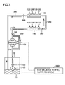
- FIG. 7 is a configuration diagram of the fuel supply system for an internal combustion engine according to the second embodiment.
- FIG. 8 is a configuration diagram showing another example of the fuel supply system for an internal combustion engine according to the second embodiment.
- FIG. 9 is a configuration diagram of a fuel supply system for an internal combustion engine according to a modification of the second embodiment.
- FIG. 10 is a configuration diagram showing another example of the fuel supply system for an internal combustion engine according to the modification of the second embodiment.
- FIG. 11 is a diagram showing a cross-sectional structure of an engine to which a fuel supply system according to the present invention is applied.
- FIG. 12 is a configuration diagram of a fuel supply system for an internal combustion engine according to a third embodiment of the present invention.
- FIG. 13 illustrates the flow of the fuel in the fuel supply system shown in FIG. 12 .
- FIG. 14 is a configuration diagram of a fuel supply system for an internal combustion engine according to a modification of the third embodiment.
- FIG. 1 schematically shows an engine system incorporating a fuel supply system for an internal combustion engine according to a first embodiment of the present invention.
- an in-line 4-cylinder gasoline engine is shown in FIG. 1 , application of the present invention is not restricted to the engine shown.
- the engine (internal combustion engine) 10 includes four cylinders 112 , which are connected via corresponding intake manifolds 20 to a common surge tank 30 .
- Surge tank 30 is connected via an intake duct 40 to an air cleaner 50 .
- an airflow meter 42 and a throttle valve 70 which is driven by an electric motor 60 , are disposed.
- Throttle valve 70 has its degree of opening controlled based on an output signal of an engine ECU (Electronic Control Unit) 300 , independently from an accelerator pedal 100 .
- Cylinders 112 are connected to a common exhaust manifold 80 , which is in turn connected to a three-way catalytic converter 90 .
- an in-cylinder injector 110 for injecting a fuel into the cylinder and an intake manifold injector 120 for injecting a fuel into an intake port and/or an intake manifold are provided.
- Injectors 110 , 120 are controlled based on output signals of engine ECU 300 .
- In-cylinder injectors 110 are connected to a common fuel delivery pipe (also referred to as “high-pressure delivery pipe” in the first embodiment) 130
- intake manifold injectors 120 are connected to a common fuel delivery pipe (also referred to as “low-pressure delivery pipe” in the first embodiment) 160 .
- Fuel supply to fuel delivery pipes 130 , 160 is carried out by a fuel supply system 150 , which will be described later in detail.
- Engine ECU 300 is configured with a digital computer, which includes a ROM (Read Only Memory) 320 , a RAM (Random Access Memory) 330 , a CPU (Central Processing Unit) 340 , an input port 350 , and an output port 360 , which are connected to each other via a bidirectional bus 310 .
- ROM Read Only Memory
- RAM Random Access Memory
- CPU Central Processing Unit
- Airflow meter 42 generates an output voltage that is proportional to an intake air amount, and the output voltage of airflow meter 42 is input via an A/D converter 370 to input port 350 .
- a coolant temperature sensor 380 is attached to engine 10 , which generates an output voltage proportional to an engine coolant temperature. The output voltage of coolant temperature sensor 380 is input via an A/D converter 390 to input port 350 .
- a fuel pressure sensor 400 is attached to high-pressure delivery pipe 130 , which generates an output voltage proportional to a fuel pressure in high-pressure delivery pipe 130 .
- the output voltage of fuel pressure sensor 400 is input via an A/D converter 410 to input port 350 .
- An air-fuel ratio sensor 420 is attached to exhaust manifold 80 located upstream of three-way catalytic converter 90 . Air-fuel ratio sensor 420 generates an output voltage proportional to an oxygen concentration in the exhaust gas, and the output voltage of air-fuel ratio sensor 420 is input via an A/D converter 430 to input port 350 .
- Air-fuel ratio sensor 420 in the engine system of the present embodiment is a full-range air-fuel ratio sensor (linear air-fuel ratio sensor) that generates an output voltage proportional to an air-fuel ratio of the air-fuel mixture burned in engine 10 .
- an O 2 sensor may be used which detects, in an on/off manner, whether the air-fuel ratio of the mixture burned in engine 10 is rich or lean with respect to a theoretical air-fuel ratio.
- Accelerator pedal 100 is connected to an accelerator press-down degree sensor 440 that generates an output voltage proportional to the degree of press-down of accelerator pedal 100 .
- the output voltage of accelerator press-down degree sensor 440 is input via an A/D converter 450 to input port 350 .
- An engine speed sensor 460 generating an output pulse representing the engine speed is connected to input port 350 .
- ROM 320 of engine ECU 300 prestores, in the form of a map, values of fuel injection quantity that are set corresponding to operation states based on the engine load factor and the engine speed obtained by the above-described accelerator press-down degree sensor 440 and engine speed sensor 460 , respectively, and the correction values based on the engine coolant temperature.
- Engine ECU 300 generates various control signals for controlling the overall operations of the engine system based on signals from the respective sensors by executing a prescribed program.
- the control signals are transmitted to the devices and circuits constituting the engine system via an output port 360 and drive circuits 470 .
- FIG. 2 illustrates in detail the configuration of fuel supply system 150 shown in FIG. 1 .
- the portions other than in-cylinder injectors 110 , high-pressure delivery pipe 130 , intake manifold injectors 120 and low-pressure delivery pipe 160 correspond to the fuel supply system 150 of FIG. 1 .
- the fuel stored in a fuel tank 200 is discharged at a prescribed pressure by a low-pressure fuel pump 180 of an electric motor-driven type.
- Low-pressure fuel pump 180 is controlled based on a control signal from an ECU 300 #.
- ECU 300 # corresponds to a functional part of engine ECU 300 of FIG. 1 that is related to control of the fuel supply system.
- low-pressure fuel pump 180 The discharge side of low-pressure fuel pump 180 is connected via a fuel filter 190 and a fuel pipe 135 to a low-pressure delivery pipe 160 that is formed as a tubular body provided with intake manifold injectors 120 . That is, low-pressure delivery pipe 160 receives the fuel discharged from low-pressure fuel pump 180 via fuel pipe 135 on the upstream side, and delivers the fuel to intake manifold injectors 120 so as to be injected into the internal combustion engine. It is noted that in the application of the present invention, an arbitrary number of (i.e., one or more) intake manifold injectors 120 may be provided to low-pressure delivery pipe 160 .
- the downstream side of low-pressure delivery pipe 160 is connected to the intake side of a high-pressure fuel pump 155 of an engine-driven type.
- Fuel pressure regulator 170 is configured to guide the fuel on the downstream side of low-pressure delivery pipe 160 to a fuel return pipe 220 when a pressure (fuel pressure) of the fuel becomes higher than a preset pressure. As such, the fuel pressure on the downstream side of fuel pressure regulator 170 is maintained so as not to exceed the preset pressure.
- the discharge side of high-pressure fuel pump 155 is connected to a fuel pipe 165 via a check valve 140 that allows the flow toward the fuel pipe 165 .
- Fuel pipe 165 is connected to a high-pressure delivery pipe 130 that is formed as a tubular body provided with in-cylinder injectors 110 . It is also noted that an arbitrary number of (i.e., one or more) in-cylinder injectors 110 may be provided to high-pressure delivery pipe 130 .
- the discharge side of high-pressure fuel pump 155 is also connected to the intake side of high-pressure fuel pump 155 via an electromagnetic spill valve 156 .
- an electromagnetic spill valve 156 As the degree of opening of electromagnetic spill valve 156 decreases, the quantity of the fuel supplied from high-pressure fuel pump 155 to fuel pipe 165 increases.
- electromagnetic spill valve 156 When electromagnetic spill valve 156 is fully open, fuel supply from high-pressure pump 155 to fuel pipe 165 is stopped.
- Electromagnetic spill valve 156 is controlled in response to an output signal of ECU 300 #.
- High-pressure delivery pipe 130 receives on its upstream side the fuel discharged from high-pressure fuel pump 155 via fuel pipe 165 , and delivers the fuel to in-cylinder injectors 110 so as to be injected into the internal combustion engine. Further, an electromagnetic relief valve 210 is provided on the downstream side of high-pressure delivery pipe 130 . Electromagnetic relief valve 210 is opened in response to a control signal from ECU 300 #, and guides the fuel within high-pressure delivery pipe 130 to fuel return pipe 220 .
- low-pressure delivery pipe 160 and high-pressure delivery pipe 130 are arranged in series, as in Japanese Patent Laying-Open No. 2004-278347 described above, and then low-pressure delivery pipe 160 is arranged upstream of fuel pressure regulator 170 .
- low-pressure fuel pump 180 and low-pressure delivery pipe 160 correspond to the “first fuel pump” and the “first fuel delivery pipe”, respectively, of the present invention.
- High-pressure fuel pump 155 and high-pressure delivery pipe 130 correspond to the “second fuel pump” and the “second fuel delivery pipe”, respectively, of the present invention.
- fuel pressure regulator 170 corresponds to the “pressure regulation unit”
- fuel return pipe 220 corresponds to the “pressure release path”
- electromagnetic relief valve 210 corresponds to the “pressure release means” of the present invention.
- operation of low-pressure fuel pump 180 is controlled in accordance with a control signal (“LOW-PRESSURE FUEL PUMP CONTROL SIGNAL” in FIG. 3 ) from engine ECU 300 that corresponds to the operation period of engine 10 .
- a control signal (“LOW-PRESSURE FUEL PUMP CONTROL SIGNAL” in FIG. 3 ) from engine ECU 300 that corresponds to the operation period of engine 10 .
- electromagnetic relief valve 210 is switched from the open state to the closed state, and the operation of low-pressure fuel pump 180 is also started.
- engine 10 is activated to enter an operating state. That is, the operations of low-pressure fuel pump 180 and electromagnetic relief valve 210 are controlled using the start of operation as a trigger, so that it is ensured that the fuel pressure in the low-pressure system is increased by driving low-pressure fuel pump 180 and electromagnetic relief valve 210 is closed at the timing of start of engine 10 .
- High-pressure fuel pump 155 also starts operation in accordance with the start of engine 10 , and fuel injection from the high-pressure system (in-cylinder injectors 110 ) becomes possible in addition to fuel injection from the low-pressure system (intake manifold injectors 120 ).
- the operation of low-pressure fuel pump 180 is stopped in response to stop of engine 10 , and electromagnetic relief valve 210 is opened.
- the start and end of the operation correspond to on and off of the ignition switch.
- the fuel discharged from low-pressure fuel pump 180 is guided through low-pressure delivery pipe 160 , fuel pressure regulator 170 , high-pressure fuel pump 155 and high-pressure delivery pipe 130 connected in series.
- low-pressure delivery pipe 160 the fuel discharged from low-pressure fuel pump 180 is guided through low-pressure delivery pipe 160 , fuel pressure regulator 170 , high-pressure fuel pump 155 and high-pressure delivery pipe 130 connected in series.
- the fuel supply system according to the modification of the first embodiment differs from the configuration example shown in FIG. 2 in that the fuel discharged from low-pressure fuel pump 180 and passed through fuel pressure regulator 170 is guided to branched paths of one directed to low-pressure delivery pipe 160 and the other directed to high-pressure delivery pipe 130 .
- Fuel pressure regulator 170 is arranged upstream of low-pressure delivery pipe 160 , and is configured to return a part of the fuel discharged from low-pressure fuel pump 180 back to fuel tank 200 when the fuel pressure of the discharged fuel becomes greater than a preset fuel pressure. This ensures that the fuel pressure on the downstream side of fuel pressure regulator 170 is maintained at the preset fuel pressure or lower.
- branched fuel pipes 135 and 136 are provided on the downstream side of fuel pressure regulator 170 .
- the fuel discharged from low-pressure fuel pump 180 and passed through fuel pressure regulator 170 is delivered via fuel pipe 135 to low-pressure delivery pipe 160 .
- An electromagnetic relief valve 205 is provided in a fuel path extending from fuel pressure regulator 170 to low-pressure delivery pipe 160 , at a certain position of fuel pipe 135 .
- electromagnetic relief valve 205 When the fuel pressure in fuel pipe 135 becomes greater than a prescribed pressure, electromagnetic relief valve 205 forms a path for guiding a part of the fuel to fuel return pipe 220 so as to lower the fuel pressure in low-pressure delivery pipe 160 and fuel pipe 135 . In addition, electromagnetic relief valve 205 is forcibly opened in response to a control signal from ECU 300 # to form a path extending from fuel pipe 135 to fuel return pipe 220 .
- Fuel pipe 136 is connected to the intake side of high-pressure fuel pump 155 .
- An electromagnetic spill valve 156 is provided on the discharge side of high-pressure fuel pump 155 .
- the discharge side of high-pressure fuel pump 155 is connected via fuel pipe 165 to high-pressure delivery pipe 130 .
- an electromagnetic relief valve 210 is arranged between the pipe 130 and fuel return pipe 220 , as in the case of the configuration example of FIG. 2 .
- electromagnetic relief valve 205 corresponds to the “first pressure release means” of the present invention
- electromagnetic relief valve 210 corresponds to the “second pressure release means” of the present invention.
- FIG. 5 illustrates operations of the electromagnetic relief valves and the low-pressure fuel pump in the fuel supply system for an internal combustion engine shown in FIG. 4 .
- low-pressure fuel pump 180 is controlled in accordance with a control signal (“LOW-PRESSURE FUEL PUMP CONTROL SIGNAL”) associated with the operation period of engine 10 , as in the case of FIG. 3 .
- a control signal (“LOW-PRESSURE FUEL PUMP CONTROL SIGNAL”) associated with the operation period of engine 10 , as in the case of FIG. 3 .
- Electromagnetic relief valves 205 and 210 are controlled in the same manner as electromagnetic relief valve 210 in FIG. 3 , i.e., closed in response to the start of operation of the vehicle and opened in response to the end of operation of the vehicle.
- the fuel pressure in high-pressure delivery pipe 130 can be lowered by opening electromagnetic relief valve 210 at the end of operation of the vehicle, and the fuel pressure in low-pressure delivery pipe 160 arranged downstream of fuel pressure regulator 170 can also be lowered sufficiently by opening electromagnetic relief valve 205 .
- opening electromagnetic relief valve 210 at the end of operation of the vehicle
- the fuel pressure in low-pressure delivery pipe 160 arranged downstream of fuel pressure regulator 170 can also be lowered sufficiently by opening electromagnetic relief valve 205 .
- each valve may be configured to guide the fuel to another location in the fuel supply system as long as it can lower the fuel pressure within the corresponding delivery pipe.
- FIG. 6 schematically shows an engine system incorporating a fuel supply system for an internal combustion engine according to a second embodiment of the present invention.
- a fuel supply system 500 of the second embodiment is provided in place of fuel supply system 150 in FIG. 1 .
- the fuel supply to fuel delivery pipes 130 and 160 is carried out by fuel supply system 500 .
- fuel delivery pipe 130 connected with in-cylinder injector 110 is also referred to as “DI delivery pipe”
- fuel delivery pipe 160 connected with intake manifold injector 120 is also referred to as “PFI delivery pipe”.
- DI delivery pipe 130 and PFI delivery pipe 160 are both subjected to heat of combustion of the fuel in the internal combustion engine.
- DI delivery pipe 130 provided with in-cylinder injector 110 arranged in the combustion chamber receives heat of a greater amount than PFI delivery pipe 160 .
- each cylinder 112 is provided with both in-cylinder injector 110 and intake manifold injector 120 .
- engine ECU 300 refers to a prepared map to set the fuel injection ratio in accordance with the engine temperature and the engine operation state (engine speed and load factor). Then, in accordance with the fuel injection ratio thus set, fuel injection is carried out using both of in-cylinder injector 110 and intake manifold injector 120 or using only in-cylinder injector 110 or intake manifold injector 120 . In a cold state of the engine, for example, the fuel injection ratio is set such that fuel injection is carried out using only intake manifold injector 120 from the standpoints of exhaust property and lubrication property, as described above.
- low-pressure fuel pump (feed pump) 180 low-pressure fuel pump (feed pump) 180 , fuel filter 190 , fuel tank 200 , high-pressure fuel pump 155 , and electromagnetic spill valve (metering valve) 156 are included in the fuel supply system 500 of FIG. 6 .
- Low-pressure fuel pump 180 of an electric motor-driven type discharges the fuel stored in fuel tank 200 at a prescribed pressure (low pressure).
- the operation period and fuel discharge quantity (flow rate) of low-pressure fuel pump 180 are controlled based on a control signal from ECU 300 #.
- ECU 300 # corresponds to a functional part of engine ECU 300 of FIG. 6 that is related to control of the fuel supply system.
- the discharge side of low-pressure fuel pump 180 is connected to the intake side of high-pressure fuel pump 155 via fuel filter 190 .
- the discharge side of high-pressure fuel pump 155 is connected to a fuel pipe 222 via a check valve 240 allowing flow directed to fuel pipe 222 .
- Fuel pipe 222 is connected to the upstream side of DI delivery pipe 130 that is formed as a tubular body provided with an arbitrary number of in-cylinder injectors 110 .
- High-pressure fuel pump 155 is also connected to the intake side of high-pressure fuel pump 155 via an electromagnetic spill valve 156 .
- High-pressure fuel pump 155 is of an engine driven type. With rotation of a pumping cam shaft driven by operation of engine 10 , for example, a plunger performs a reciprocating motion within a cylinder, and thus, the fuel suctioned into a pressurizing chamber is compressed and increased in pressure, and is discharged at a prescribed pressure (high pressure on the order of 12 MPa, for example).
- the prescribed pressure (high pressure) is set to a level required for atomization of the fuel injected into the cylinder.
- electromagnetic spill valve 156 is opened.
- the fuel compressed by the plunger in the pressurizing chamber is delivered to fuel pipe 222 while electromagnetic spill valve 156 is closed, and while electromagnetic spill valve 156 is open, the fuel within the pressurizing chamber flows back to the intake side of high-pressure fuel pump 155 , with no fuel compressing operation being conducted.
- DI delivery pipe 130 receives the fuel discharged from high-pressure fuel pump 155 via fuel pipe 222 on the upstream side, and delivers the fuel to an arbitrary number of in-cylinder injectors 110 for injection into the internal combustion engine (in-cylinder injection). Further, a mechanical relief valve 250 is provided on the downstream side of DI delivery pipe 130 . Mechanical relief valve 250 opens when a pressure equal to or greater than a set pressure (high pressure on the order of 12 MPa, for example) is applied, and guides the fuel within DI delivery pipe 130 to a connection pipe 224 . As such, the fuel pressure within DI delivery pipe 130 is maintained at a prescribed level.
- a set pressure high pressure on the order of 12 MPa, for example
- connection pipe 224 The fuel sent out of DI delivery pipe 130 via connection pipe 224 is supplied to the upstream side of PFI delivery pipe 160 .
- PFI delivery pipe 160 receives the fuel from connection pipe 224 on the upstream side, and delivers the fuel to an arbitrary number of intake manifold injectors 120 for injection into the internal combustion engine (intake manifold injection).
- a pressure regulator 260 is provided downstream of PFI delivery pipe 160 between the pipe 160 and a pressure release path 230 .
- Pressure regulator 260 is configured to guide the fuel on the downstream side of PFI delivery pipe 160 to pressure release path 230 when its fuel pressure becomes higher than a preset fuel pressure (low pressure on the order of 400 kPa, for example).
- a preset fuel pressure low pressure on the order of 400 kPa, for example.
- the fuel pressure within PFI delivery pipe 160 is maintained at a prescribed pressure (low pressure) that is lower than the fuel pressure (high pressure) within DI delivery pipe 130 .
- the fuel guided to pressure release path 230 is returned to fuel tank 200 , for example.
- the prescribed pressure may be set lower than the discharge pressure (i.e., high pressure) of high-pressure fuel pump 155 , since it only needs to be a level required for atomization of the fuel injected into the intake manifold.
- the set fuel pressure in PFI delivery pipe 160 lower than that in DI delivery pipe 130 , the designed withstand pressure of intake manifold injectors 120 and PFI delivery pipe 160 not requiring fuel injection at high pressure can be lowered, leading to reduction of manufacture cost.
- DI delivery pipe 130 for in-cylinder fuel injection receiving a relatively large amount of heat from the internal combustion engine is arranged upstream.
- the fuel to be injected from intake manifold injectors 120 is supplied to PFI delivery pipe 160 after being passed through DI delivery pipe 130 that receives the large amount of heat.
- the temperature of the fuel within PFI delivery pipe 160 that is, the temperature of the fuel injected from intake manifold injectors 120
- the temperature of the fuel within PFI delivery pipe 160 can be increased quickly.
- deposits may be produced due to the temperature increase of in-cylinder injectors 110 .
- the fuel to be injected from both of in-cylinder injector 110 and intake manifold injector 120 that is, all the fuel to be injected, is passed through DI delivery pipe 130 , so that it is possible to restrict the increase in temperature of the fuel within DI delivery pipe 130 .
- This ensures the effect of cooling in-cylinder injector 110 by the fuel passed through DI delivery pipe 130 , or the fuel being injected therefrom. Accordingly, production of deposits can be prevented by restricting the increase in temperature at the tip of in-cylinder injector 110 .
- low-pressure fuel pump 180 and high-pressure fuel pump 155 each correspond to the “fuel pump” of the present invention
- PFI delivery pipe 160 and DI delivery pipe 130 correspond to the “first fuel delivery pipe” and the “second fuel delivery pipe”, respectively, of the present invention
- mechanical relief valve 250 corresponds to the “first fuel pressure regulation means”
- pressure regulator 260 corresponds to the “second fuel pressure regulation means” of the present invention.
- the fuel discharge quantity of high-pressure fuel pump 155 is relatively large, since it needs to discharge the fuel for both of in-cylinder injection and intake manifold injection. For this reason, high-pressure fuel pump 155 may have a simple configuration to compress all the suctioned fuel and discharge the resultant fuel into fuel pipe 222 , without provision of the above-described electromagnetic spill valve 156 enabling adjustment of the discharge quantity.
- a relief valve 255 equipped with an electromagnetic valve may be provided downstream of DI delivery pipe 130 , instead of mechanical relief valve 250 .
- relief valve 255 functions in the same manner as mechanical relief valve 250 shown in FIG. 7 and, in addition, opens in response to an electromagnetic valve open instruction SV 0 from ECU 300 # so as to connect the downstream side of DI delivery pipe 130 as well as connection pipe 224 (that is, the upstream side of PFI delivery pipe 160 ) to pressure release path 230 .
- the fuel supply system according to the modification of the second embodiment differs from the fuel supply systems shown in FIGS. 7 and 8 in that fuel pressure regulation means (mechanical relief valve 250 in FIG. 7 or relief valve 255 equipped with electromagnetic valve in FIG. 8 ) is not provided downstream of DI delivery pipe 130 , and in that a mechanical relief valve 270 is provided between the downstream side of PFI delivery pipe 160 and pressure release path 230 .
- fuel pressure regulation means mechanical relief valve 250 in FIG. 7 or relief valve 255 equipped with electromagnetic valve in FIG. 8
- Mechanical relief valve 270 has the function similar to that of mechanical relief valve 250 shown in FIG. 7 . It opens when a pressure equal to or greater than a set pressure (high pressure on the order of 12 MPa, for example) is applied, to guide the fuel within PFI delivery pipe 160 to pressure release path 230 . That is, mechanical relief valve 270 corresponds to the “fuel pressure regulation means” of the present invention.
- the fuel pressure of PFI delivery pipe 160 is set to a high pressure similarly to that of DI delivery pipe 130 .
- the fuel injection from in-cylinder injectors 110 but also the fuel injection from intake manifold injectors 120 is carried out, at high pressure.
- mechanical relief valve 270 provided downstream of PFI delivery pipe 160 may be replaced with a relief valve 275 that opens in response to an electromagnetic valve open instruction SV 0 , as shown in FIG. 10 .
- relief valve 275 functions in the same manner as mechanical relief valve 270 , and additionally serves to connect the downstream side of PFI delivery pipe 160 to pressure release path 230 in response to electromagnetic valve open instruction SV 0 from ECU 300 #.
- relief valve 275 When relief valve 275 is opened by the instruction from ECU 300 # at the time of stop of vehicle operation as in the case of electromagnetic valve-equipped relief valve 255 , the fuel pressure in DI delivery pipe 130 and in PFI delivery pipe 160 can be lowered sufficiently. This improves oil tightness of in-cylinder injectors 110 and intake manifold injectors 120 during the stop of vehicle operation and, as a result, degradation in exhaust emission property at the next engine start due to the fuel leaking from the injectors can be suppressed.
- a third embodiment of the present invention will now be described with reference to FIGS. 11-14 .
- the fuel supply system of the present invention is applied to an in-line 4-cylinder engine.
- FIG. 11 shows a cross-sectional structure of an engine 501 to which the fuel supply system of the present invention is applied.
- Engine 501 is provided with a cylinder block 502 and a cylinder head 503 .
- a cylinder 521 is provided in cylinder block 502 .
- a piston 522 is contained in cylinder 521 in a reciprocable manner.
- a combustion chamber 523 is formed in cylinder 521 , which is surrounded by the inner peripheral surface of cylinder 521 , the top face of piston 522 and cylinder head 503 .
- An intake pipe 531 and an exhaust pipe 532 are provided at cylinder head 503 .
- Intake pipe 531 is connected to combustion chamber 523 via an intake port 533 .
- an intake valve 535 is arranged, which opens/closes intake port 533 to change the connection state between intake pipe 531 and combustion chamber 523 .
- Exhaust pipe 532 is connected to combustion chamber 523 via an exhaust port 534 .
- an exhaust valve 536 is arranged, which opens/closes exhaust port 534 to change the connection state between exhaust pipe 532 and combustion chamber 523 .
- Fuel supply system 505 includes a fuel tank 551 , an arbitrary number of in-cylinder injectors DI and an arbitrary number of port injectors PI. The fuel within fuel tank 551 is supplied to in-cylinder injectors DI and port injectors PI.
- In-cylinder injector DI injects the fuel into combustion chamber 523 . That is, in-cylinder injector DI is provided at cylinder head 503 , with its injection hole arranged inside combustion chamber 523 .
- Port injector PI injects the fuel into intake port 533 . That is, port injector PI is provided at cylinder head 503 , with its injection hole arranged inside the intake manifold.
- engine 10 shown in FIGS. 1 and 6 has a cross-sectional structure similar to that of engine 501 in FIG. 11 . That is, in-cylinder injector DI and port injector PI of the third embodiment correspond to in-cylinder injector 110 and intake manifold injector 120 , respectively, of the first and second embodiments.
- FIG. 12 shows a structure of fuel supply system 505 of FIG. 11 .
- a low-pressure fuel pump 552 pumps a fuel from a fuel tank 551 and discharges the fuel to a high-pressure fuel pump 553 .
- a fuel pump of an electric type discharging the fuel in a constant quantity may be used.
- High-pressure fuel pump 553 applies pressure to the fuel discharged from low-pressure fuel pump 552 and discharges the resultant fuel to injectors DI, PI.
- a fuel pump of a mechanical type applying pressure to the fuel by a reciprocating motion of a plunger via a camshaft may be used.
- the camshaft is driven via a crankshaft of engine 501 .
- the fuel discharge quantity of low-pressure fuel pump 552 is set such that the fuel of a sufficient quantity is supplied to high-pressure fuel pump 553 even when high-pressure fuel pump 553 is operating at the maximum rotational speed.
- An in-cylinder injection fuel delivery pipe 554 supplies the fuel to in-cylinder injectors DI.
- In-cylinder injectors DI are provided at in-cylinder injection fuel delivery pipe 554 , and each inject the fuel into combustion chamber 523 of the corresponding cylinder 521 .
- a port injection fuel delivery pipe 555 supplies the fuel to port injectors PI.
- Port injectors PI are provided at port injection fuel delivery pipe 555 , and each inject the fuel into intake port 533 of the corresponding cylinder 521 .
- An in-cylinder injection pressure regulation valve 556 regulates the pressure of the fuel within in-cylinder injection fuel delivery pipe 554 not to exceed an in-cylinder injection pressure PA.
- This in-cylinder injection pressure PA corresponds to the fuel pressure that is required to ensure accurate fuel injection via in-cylinder injectors DI.
- a port injection pressure regulation valve 557 regulates the pressure of the fuel within port injection fuel delivery pipe 555 not to exceed a port injection pressure PB.
- This port injection pressure PB corresponds to the fuel pressure that is required to ensure accurate fuel injection via port injectors PI, which is set to a level lower than in-cylinder injection pressure PA.
- port injection fuel delivery pipe 555 corresponds to the “intake manifold injection fuel delivery pipe” of the present invention
- port injection pressure regulation valve 557 corresponds to the “intake manifold injection pressure regulation means” of the present invention.
- In-cylinder injection pressure regulation valve 556 includes an inlet port 556 A and an outlet port 556 B, and also includes an open/close valve that opens/closes a fuel passage (connecting the inlet port 556 A and the outlet port 556 B) formed therein.
- the open/close valve is normally held at a position closing the fuel passage via a pressure regulation spring.
- the open/close valve moves to open the fuel passage, to cause the fuel within in-cylinder injection fuel delivery pipe 554 to flow out to the downstream side of in-cylinder injection pressure regulation valve 556 via outlet port 556 B.
- the open/close valve moves to close the fuel passage, so that the flow of the fuel from the inlet port 556 A to outlet port 556 B is shut off.
- Port injection pressure regulation valve 557 includes an inlet port 557 A and an outlet port 557 B, and also includes an open/close valve that opens/closes a fuel passage (connecting the inlet port 557 A and the outlet port 557 B) formed therein.
- the open/close valve is normally held at the position closing the fuel passage via a pressure regulation spring.
- the open/close valve moves to open the fuel passage, so that the fuel within port injection fuel delivery pipe 555 flows out to the downstream side of port injection pressure regulation valve 557 via outlet port 557 B.
- fuel supply system 505 the elements are connected through the fuel pipes as follows.
- the discharge side of low-pressure fuel pump 552 is connected to the intake side of high-pressure fuel pump 553 via a first fuel pipe R 1 .
- the discharge side of high-pressure fuel pump 553 is connected to the upstream side of in-cylinder injection fuel delivery pipe 554 via a second fuel pipe R 2 .
- Inlet port 556 A of in-cylinder injection pressure regulation valve 556 is connected to second fuel pipe R 2 .
- Outlet port 556 B of in-cylinder injection pressure regulation valve 556 is connected to the upstream side of port injection fuel delivery pipe 555 via a connection fuel pipe RE.
- port injection fuel delivery pipe 555 The downstream side of port injection fuel delivery pipe 555 is connected to inlet port 557 A of port injection pressure regulation valve 557 via a third fuel pipe R 3 .
- Outlet port 557 B of port injection pressure regulation valve 557 is connected to fuel tank 551 via a fourth fuel pipe R 4 .
- first fuel pipe R 1 and second fuel pipe R 2 correspond to the “fuel supply pipe” of the present invention
- third fuel pipe R 3 and fourth fuel pipe R 4 correspond to the “fuel return pipe” of the present invention.
- FIG. 13 illustrates the flow of the fuel in fuel supply system 505 during the operation of the engine.
- the fuel within fuel tank 551 is discharged to first fuel pipe R 1 via low-pressure fuel pump 552 .
- the fuel pressure within first fuel pipe R 1 is maintained not to exceed a discharge pressure (feed pressure PC) of low-pressure fuel pump 552 .
- All of the fuel discharged from low-pressure fuel pump 552 is supplied via first fuel pipe R 1 to high-pressure fuel pump 553 .
- the fuel supplied to high-pressure fuel pump 553 is applied with pressure by high-pressure fuel pump 553 to attain a pressure greater than feed pressure PC before being discharged to second fuel pipe R 2 .
- the fuel discharged from high-pressure fuel pump 553 is supplied via second fuel pipe R 2 to in-cylinder injection fuel delivery pipe 554 .
- the fuel pressure within in-cylinder injection fuel delivery pipe 554 (and in second fuel pipe R 2 ) is maintained not to exceed in-cylinder injection pressure PA by in-cylinder injection pressure regulation valve 556 .
- connection fuel pipe RE The fuel flown out of outlet port 556 B of in-cylinder injection pressure regulation valve 556 is supplied via connection fuel pipe RE to port injection fuel delivery pipe 555 .
- the fuel pressure within port injection fuel delivery pipe 555 (and in connection fuel pipe RE) is maintained not to exceed port injection pressure PB by port injection pressure regulation valve 557 .
- the fuel flown out of outlet port 557 B of port injection pressure regulation valve 557 is returned to fuel tank 551 via fourth fuel pipe R 4 .
- the fuel pressure within fourth fuel pipe R 4 is maintained not to exceed a return pressure PD corresponding to the pressure within fuel tank 551 .
- the pressure of the fuel within port injection fuel delivery pipe 555 is regulated by port injection pressure regulation valve 557 . This ensures accurate fuel injection from port injectors PI.
- the fuel path is branched at the downstream side of high-pressure fuel pump 553 to the path for supplying the fuel to in-cylinder injection fuel delivery pipe 554 and the path for supplying the fuel to port injection fuel delivery pipe 555 .
- the path for supplying the fuel to in-cylinder injection fuel delivery pipe 554 and the path for supplying the fuel to port injection fuel delivery pipe 555 were branched at the upstream side of high-pressure fuel pump 553 , it would be necessary to set the discharge quantity of low-pressure fuel pump 552 taking account of the fuel injection quantity from port injectors PI in addition to the fuel required at the maximum rotational speed of high-pressure fuel pump 553 . That is, in order to avoid insufficient fuel supply to high-pressure fuel pump 553 , the discharge quantity of low-pressure fuel pump 552 would have to be set greater than in the case of the present embodiment.
- the fuel supply system of the modification of the third embodiment has the piping structure of the fuel supply system of the third embodiment modified as follows.
- FIG. 14 shows a structure of the fuel supply system 505 # according to the modification of the third embodiment.
- the fuel supply system of the modification of the third embodiment has the configuration similar to that of the fuel supply system of the third embodiment except for the following point.
- first fuel pipe R 1 , second fuel pipe R 2 and fifth fuel pipe R 5 correspond to the “fuel supply pipe” of the present invention.
- port injector PI for injecting the fuel into intake port 533 has been provided.
- Port injector PI may be replaced with any other injector, as long as it can serve as an intake manifold injector for injecting the fuel into an intake manifold (including intake port, surge tank and the like).
- the present invention has been applied to a fuel supply system for an in-line 4-cylinder engine.
- the present invention is applicable to any fuel supply system including an in-cylinder injector and an intake manifold injector, to provide the similar effects.
Landscapes
- Engineering & Computer Science (AREA)
- Chemical & Material Sciences (AREA)
- Combustion & Propulsion (AREA)
- Mechanical Engineering (AREA)
- General Engineering & Computer Science (AREA)
- Fuel-Injection Apparatus (AREA)
Priority Applications (2)
| Application Number | Priority Date | Filing Date | Title |
|---|---|---|---|
| US11/790,649 US7353798B2 (en) | 2004-07-02 | 2007-04-26 | Fuel supply system for internal combustion engine |
| US11/790,651 US20070199542A1 (en) | 2004-07-02 | 2007-04-26 | Fuel supply system for internal combustion engine |
Applications Claiming Priority (6)
| Application Number | Priority Date | Filing Date | Title |
|---|---|---|---|
| JP2004-197351 | 2004-07-02 | ||
| JP2004197351A JP2006017059A (ja) | 2004-07-02 | 2004-07-02 | エンジンの燃料供給装置 |
| JP2004-336114 | 2004-11-19 | ||
| JP2004336114A JP2006144666A (ja) | 2004-11-19 | 2004-11-19 | 内燃機関の燃料供給システム |
| JP2004362838A JP2006170048A (ja) | 2004-12-15 | 2004-12-15 | 車両の燃料噴射装置 |
| JP2004-362838 | 2004-12-15 |
Related Child Applications (2)
| Application Number | Title | Priority Date | Filing Date |
|---|---|---|---|
| US11/790,651 Division US20070199542A1 (en) | 2004-07-02 | 2007-04-26 | Fuel supply system for internal combustion engine |
| US11/790,649 Division US7353798B2 (en) | 2004-07-02 | 2007-04-26 | Fuel supply system for internal combustion engine |
Publications (2)
| Publication Number | Publication Date |
|---|---|
| US20060000452A1 US20060000452A1 (en) | 2006-01-05 |
| US7263972B2 true US7263972B2 (en) | 2007-09-04 |
Family
ID=34971525
Family Applications (3)
| Application Number | Title | Priority Date | Filing Date |
|---|---|---|---|
| US11/166,281 Expired - Fee Related US7263972B2 (en) | 2004-07-02 | 2005-06-27 | Fuel supply system for internal combustion engine |
| US11/790,649 Expired - Fee Related US7353798B2 (en) | 2004-07-02 | 2007-04-26 | Fuel supply system for internal combustion engine |
| US11/790,651 Abandoned US20070199542A1 (en) | 2004-07-02 | 2007-04-26 | Fuel supply system for internal combustion engine |
Family Applications After (2)
| Application Number | Title | Priority Date | Filing Date |
|---|---|---|---|
| US11/790,649 Expired - Fee Related US7353798B2 (en) | 2004-07-02 | 2007-04-26 | Fuel supply system for internal combustion engine |
| US11/790,651 Abandoned US20070199542A1 (en) | 2004-07-02 | 2007-04-26 | Fuel supply system for internal combustion engine |
Country Status (3)
| Country | Link |
|---|---|
| US (3) | US7263972B2 (de) |
| EP (1) | EP1763631A2 (de) |
| WO (1) | WO2006004026A2 (de) |
Cited By (6)
| Publication number | Priority date | Publication date | Assignee | Title |
|---|---|---|---|---|
| US20070068525A1 (en) * | 2004-09-07 | 2007-03-29 | Michael Offenhuber | Apparatus for introducing a reducing agent into the exhaust of an internal combustion engine |
| US20090064971A1 (en) * | 2007-09-11 | 2009-03-12 | C.R.F. Consortile Per Azioni | Fuel injection system comprising a variable flow rate high-pressure pump |
| US20090276144A1 (en) * | 2006-11-20 | 2009-11-05 | Toyota Jidosha Kabushiki Kaisha | Control device for internal combustion engine |
| US20130243636A1 (en) * | 2012-03-19 | 2013-09-19 | Hitachi, Ltd | Fuel pump for an internal combustion engine |
| US20160123291A1 (en) * | 2013-06-28 | 2016-05-05 | Isuzu Motors Limited | Control device for common rail fuel injection device |
| US20170211504A1 (en) * | 2014-10-14 | 2017-07-27 | Continental Automotive Gmbh | Fuel-Supply System For An Internal Combustion Engine |
Families Citing this family (34)
| Publication number | Priority date | Publication date | Assignee | Title |
|---|---|---|---|---|
| JP3894179B2 (ja) * | 2003-10-02 | 2007-03-14 | トヨタ自動車株式会社 | 内燃機関の燃料供給装置 |
| JP4432610B2 (ja) * | 2004-05-17 | 2010-03-17 | トヨタ自動車株式会社 | 内燃機関の燃料供給装置 |
| EP1763631A2 (de) * | 2004-07-02 | 2007-03-21 | Toyota Jidosha Kabushiki Kaisha | Kraftstoffzufuhrsystem für verbrennungsmotor |
| EP1918552B1 (de) * | 2006-10-24 | 2009-08-19 | Honda Motor Co., Ltd. | Internes EGR-Steuersystem für einen Verbrennungsmotor |
| JP4563370B2 (ja) * | 2006-12-28 | 2010-10-13 | 本田技研工業株式会社 | 内燃機関の燃料噴射制御装置 |
| US8327827B2 (en) * | 2007-10-31 | 2012-12-11 | Brp Us Inc. | Fuel-injected engine and method of assembly thereof |
| DE102008036122B4 (de) * | 2008-08-01 | 2014-07-10 | Continental Automotive Gmbh | Verfahren zur Adaption der Leistung einer Kraftstoffvorförderpumpe eines Kraftfahrzeugs |
| US7757672B2 (en) * | 2008-09-15 | 2010-07-20 | Gm Global Technology Operations, Inc. | Anti-clogging fuel pump module |
| NL2002383C2 (nl) * | 2008-12-30 | 2010-07-01 | Vialle Alternative Fuel Systems Bv | Brandstoftoevoersysteem en werkwijze voor het toevoeren van brandstof aan een verbrandingsruimte. |
| DE102009008832A1 (de) * | 2009-02-13 | 2010-08-19 | Audi Ag | Brennkraftmaschine für einen Kraftwagen |
| US8042520B2 (en) * | 2009-05-12 | 2011-10-25 | GM Global Technology Operations LLC | Engine startup fuel pressure control systems and methods |
| EP2317105B1 (de) | 2009-10-28 | 2012-07-11 | Hitachi Ltd. | Hochdruck-Brennstoffförderpumpe und Brennstofffördersystem |
| US8439016B2 (en) * | 2009-12-15 | 2013-05-14 | GM Global Technology Operations LLC | Liquefied petroleum gas engine assembly with flow control |
| DE102011007642B3 (de) | 2011-04-19 | 2012-07-26 | Continental Automotive Gmbh | Verfahren zum Betreiben einer Brennkraftmaschine und Brennkraftmaschine |
| DE102011086201A1 (de) * | 2011-11-11 | 2013-05-16 | Mahle International Gmbh | Kraftstoffeinspritzanlage und Vorheizeinrichtung |
| JP5975672B2 (ja) * | 2012-02-27 | 2016-08-23 | 日立オートモティブシステムズ株式会社 | 電磁駆動型の吸入弁を備えた高圧燃料供給ポンプ |
| US8997714B2 (en) * | 2013-03-28 | 2015-04-07 | Ford Global Technologies, Llc | Method for operating a direct fuel injector |
| US20140353262A1 (en) * | 2013-05-31 | 2014-12-04 | Carter Fuel Systems, Llc | Self-cleaning fuel pump |
| GB201317731D0 (en) * | 2013-10-08 | 2013-11-20 | Rolls Royce Plc | Fuel delivery system |
| JP2016017403A (ja) * | 2014-07-04 | 2016-02-01 | 株式会社デンソー | 燃料供給装置 |
| US9611801B2 (en) | 2014-12-15 | 2017-04-04 | Ford Global Technologies, Llc | Methods and systems for fixed and variable pressure fuel injection |
| US9726106B2 (en) | 2014-12-15 | 2017-08-08 | Ford Global Technologies, Llc | Methods and systems for high pressure port fuel injection |
| US9752530B2 (en) | 2014-12-15 | 2017-09-05 | Ford Global Technologies, Llc | Methods and systems for fixed and variable pressure fuel injection |
| US9670867B2 (en) | 2015-06-25 | 2017-06-06 | Ford Global Technologies, Llc | Systems and methods for fuel injection |
| US10100774B2 (en) * | 2015-06-25 | 2018-10-16 | Ford Global Technologies, Llc | Systems and methods for fuel injection |
| US9771910B2 (en) * | 2015-06-25 | 2017-09-26 | Ford Global Technologies, Llc | Systems and methods for fuel injection |
| US9970379B2 (en) | 2016-02-29 | 2018-05-15 | Ford Global Technologies, Llc | Methods and systems for fuel rail pressure relief |
| US10215144B1 (en) * | 2017-10-11 | 2019-02-26 | Robert Bosch Gmbh | Fuel system with switchable pressure regulation |
| KR20190044760A (ko) * | 2017-10-23 | 2019-05-02 | 현대자동차주식회사 | 마일드 하이브리드 차량의 제어 방법 및 그 제어 장치 |
| JP7035577B2 (ja) * | 2018-02-02 | 2022-03-15 | マツダ株式会社 | エンジンの燃料供給装置 |
| JP7102755B2 (ja) * | 2018-02-02 | 2022-07-20 | マツダ株式会社 | エンジンの燃料供給装置 |
| DE102019101135A1 (de) * | 2019-01-17 | 2020-07-23 | Bayerische Motoren Werke Aktiengesellschaft | Brennkraftmaschine mit einem Kraftstoffeinspritzsystem |
| US11125196B2 (en) * | 2019-05-10 | 2021-09-21 | Walbro Llc | Bottom mount fuel pump assembly |
| WO2023150621A1 (en) * | 2022-02-02 | 2023-08-10 | Stanadyne Llc | High pressure port fuel injection system |
Citations (14)
| Publication number | Priority date | Publication date | Assignee | Title |
|---|---|---|---|---|
| FR2669377A1 (fr) | 1990-11-19 | 1992-05-22 | Peugeot | Moteur a combustion interne alimente selon deux modes d'injection. |
| US5207203A (en) | 1992-03-23 | 1993-05-04 | General Motors Corporation | Fuel system |
| JPH07103048A (ja) | 1993-10-06 | 1995-04-18 | Toyota Motor Corp | 内燃機関の燃料噴射装置 |
| JPH11287148A (ja) | 1998-04-02 | 1999-10-19 | Fuji Heavy Ind Ltd | 内燃機関の燃料噴射装置 |
| JP2000274329A (ja) | 1999-03-25 | 2000-10-03 | Toyota Motor Corp | 内燃機関の燃料噴射装置 |
| JP2001065421A (ja) | 1999-08-24 | 2001-03-16 | Sanshin Ind Co Ltd | 燃料噴射式エンジン |
| EP1188919A2 (de) | 2000-09-18 | 2002-03-20 | Hitachi, Ltd. | Kraftstoffversorgungssystem |
| US6397819B1 (en) | 1998-05-27 | 2002-06-04 | Robert Bosch Gmbh | Fuel supply system in an internal combustion engine |
| US20030041838A1 (en) | 2001-08-31 | 2003-03-06 | Toyota Jidosha Kabushiki Kaisha | Fuel injection device of cylinder injection type internal combustion engine and fuel injection method thereof |
| JP2004060474A (ja) | 2002-07-25 | 2004-02-26 | Hitachi Ltd | 内燃機関の燃焼制御装置 |
| JP2004278347A (ja) | 2003-03-13 | 2004-10-07 | Toyota Motor Corp | 燃料噴射装置 |
| US20050193982A1 (en) * | 2004-03-02 | 2005-09-08 | Toyota Jidosha Kabushiki Kaisha | Fuel supply apparatus for internal combustion engine |
| US20050268889A1 (en) * | 2004-05-17 | 2005-12-08 | Toyota Jidosha Kabushiki Kaisha | Fuel supply apparatus for internal combustion engine |
| US20060207567A1 (en) * | 2005-03-18 | 2006-09-21 | Toyota Jidosha Kabushiki Kaisha | Control apparatus for vehicle |
Family Cites Families (6)
| Publication number | Priority date | Publication date | Assignee | Title |
|---|---|---|---|---|
| JPH10176574A (ja) * | 1996-12-19 | 1998-06-30 | Toyota Motor Corp | 内燃機関の燃料噴射制御装置 |
| EP1763631A2 (de) * | 2004-07-02 | 2007-03-21 | Toyota Jidosha Kabushiki Kaisha | Kraftstoffzufuhrsystem für verbrennungsmotor |
| JP4438553B2 (ja) * | 2004-07-30 | 2010-03-24 | トヨタ自動車株式会社 | 内燃機関の高圧燃料系統の制御装置 |
| JP2006132517A (ja) * | 2004-10-07 | 2006-05-25 | Toyota Motor Corp | 内燃機関の燃料噴射装置および内燃機関の高圧燃料系統の制御装置 |
| JP4466340B2 (ja) * | 2004-11-18 | 2010-05-26 | トヨタ自動車株式会社 | 燃料供給装置 |
| JP4428293B2 (ja) * | 2005-06-07 | 2010-03-10 | トヨタ自動車株式会社 | 内燃機関の制御装置 |
-
2005
- 2005-06-24 EP EP05755851A patent/EP1763631A2/de not_active Withdrawn
- 2005-06-24 WO PCT/JP2005/012175 patent/WO2006004026A2/en not_active Application Discontinuation
- 2005-06-27 US US11/166,281 patent/US7263972B2/en not_active Expired - Fee Related
-
2007
- 2007-04-26 US US11/790,649 patent/US7353798B2/en not_active Expired - Fee Related
- 2007-04-26 US US11/790,651 patent/US20070199542A1/en not_active Abandoned
Patent Citations (15)
| Publication number | Priority date | Publication date | Assignee | Title |
|---|---|---|---|---|
| FR2669377A1 (fr) | 1990-11-19 | 1992-05-22 | Peugeot | Moteur a combustion interne alimente selon deux modes d'injection. |
| US5207203A (en) | 1992-03-23 | 1993-05-04 | General Motors Corporation | Fuel system |
| JPH07103048A (ja) | 1993-10-06 | 1995-04-18 | Toyota Motor Corp | 内燃機関の燃料噴射装置 |
| JPH11287148A (ja) | 1998-04-02 | 1999-10-19 | Fuji Heavy Ind Ltd | 内燃機関の燃料噴射装置 |
| US6397819B1 (en) | 1998-05-27 | 2002-06-04 | Robert Bosch Gmbh | Fuel supply system in an internal combustion engine |
| JP2000274329A (ja) | 1999-03-25 | 2000-10-03 | Toyota Motor Corp | 内燃機関の燃料噴射装置 |
| JP2001065421A (ja) | 1999-08-24 | 2001-03-16 | Sanshin Ind Co Ltd | 燃料噴射式エンジン |
| EP1188919A2 (de) | 2000-09-18 | 2002-03-20 | Hitachi, Ltd. | Kraftstoffversorgungssystem |
| US20030041838A1 (en) | 2001-08-31 | 2003-03-06 | Toyota Jidosha Kabushiki Kaisha | Fuel injection device of cylinder injection type internal combustion engine and fuel injection method thereof |
| JP2003074441A (ja) | 2001-08-31 | 2003-03-12 | Toyota Motor Corp | 筒内噴射式内燃機関の燃料噴射装置 |
| JP2004060474A (ja) | 2002-07-25 | 2004-02-26 | Hitachi Ltd | 内燃機関の燃焼制御装置 |
| JP2004278347A (ja) | 2003-03-13 | 2004-10-07 | Toyota Motor Corp | 燃料噴射装置 |
| US20050193982A1 (en) * | 2004-03-02 | 2005-09-08 | Toyota Jidosha Kabushiki Kaisha | Fuel supply apparatus for internal combustion engine |
| US20050268889A1 (en) * | 2004-05-17 | 2005-12-08 | Toyota Jidosha Kabushiki Kaisha | Fuel supply apparatus for internal combustion engine |
| US20060207567A1 (en) * | 2005-03-18 | 2006-09-21 | Toyota Jidosha Kabushiki Kaisha | Control apparatus for vehicle |
Cited By (12)
| Publication number | Priority date | Publication date | Assignee | Title |
|---|---|---|---|---|
| US20070068525A1 (en) * | 2004-09-07 | 2007-03-29 | Michael Offenhuber | Apparatus for introducing a reducing agent into the exhaust of an internal combustion engine |
| US7594393B2 (en) * | 2004-09-07 | 2009-09-29 | Robert Bosch Gmbh | Apparatus for introducing a reducing agent into the exhaust of an internal combustion engine |
| US20090276144A1 (en) * | 2006-11-20 | 2009-11-05 | Toyota Jidosha Kabushiki Kaisha | Control device for internal combustion engine |
| US7891341B2 (en) * | 2006-11-20 | 2011-02-22 | Toyota Jidosha Kabushiki Kaisha | Control device for internal combustion engine |
| US20090064971A1 (en) * | 2007-09-11 | 2009-03-12 | C.R.F. Consortile Per Azioni | Fuel injection system comprising a variable flow rate high-pressure pump |
| US7779815B2 (en) * | 2007-09-11 | 2010-08-24 | C.R.F. Societa Consortile Per Azioni | Fuel injection system comprising a variable flow rate high-pressure pump |
| US20130243636A1 (en) * | 2012-03-19 | 2013-09-19 | Hitachi, Ltd | Fuel pump for an internal combustion engine |
| US9562504B2 (en) * | 2012-03-19 | 2017-02-07 | Hitachi, Ltd | Fuel pump for an internal combustion engine |
| US20160123291A1 (en) * | 2013-06-28 | 2016-05-05 | Isuzu Motors Limited | Control device for common rail fuel injection device |
| US9790908B2 (en) * | 2013-06-28 | 2017-10-17 | Isuzu Motors Limited | Control device for common rail fuel injection device |
| US20170211504A1 (en) * | 2014-10-14 | 2017-07-27 | Continental Automotive Gmbh | Fuel-Supply System For An Internal Combustion Engine |
| US10309335B2 (en) * | 2014-10-14 | 2019-06-04 | Continental Automotive Gmbh | Fuel-supply system for an internal combustion engine |
Also Published As
| Publication number | Publication date |
|---|---|
| US20070193559A1 (en) | 2007-08-23 |
| US7353798B2 (en) | 2008-04-08 |
| WO2006004026A3 (en) | 2006-03-02 |
| WO2006004026A2 (en) | 2006-01-12 |
| EP1763631A2 (de) | 2007-03-21 |
| US20060000452A1 (en) | 2006-01-05 |
| US20070199542A1 (en) | 2007-08-30 |
Similar Documents
| Publication | Publication Date | Title |
|---|---|---|
| US7263972B2 (en) | Fuel supply system for internal combustion engine | |
| US7464696B2 (en) | Fuel supply apparatus | |
| US7178506B2 (en) | Fuel supply apparatus for internal combustion engine | |
| US7328687B2 (en) | Fuel supply apparatus for internal combustion engine | |
| US7806104B2 (en) | Control apparatus for internal combustion engine | |
| US7789071B2 (en) | Fuel supply system for an internal combustion engine | |
| US9169815B2 (en) | High-pressure fuel supply apparatus for internal combustion engine | |
| US7051713B2 (en) | Fuel injection control apparatus for internal combustion engine | |
| RU2358144C1 (ru) | Устройство подачи топлива для транспортного средства | |
| US7318413B2 (en) | Control apparatus for internal combustion engine | |
| US7219654B2 (en) | Fuel injection device for an internal combustion engine | |
| CN100516502C (zh) | 用于内燃机的燃料供应系统 | |
| US20140251280A1 (en) | Control apparatus for internal combustion engine and control method for internal combustion engine | |
| JP3786002B2 (ja) | 内燃機関の高圧燃料供給装置 | |
| US8051838B2 (en) | Fuel injection control device | |
| JP5989406B2 (ja) | 燃料圧力制御装置 | |
| JP4046068B2 (ja) | 内燃機関の燃料噴射制御装置 | |
| JP2998558B2 (ja) | 内燃機関用燃料供給装置及び燃料供給方法 | |
| JP2006144666A (ja) | 内燃機関の燃料供給システム | |
| JP4329755B2 (ja) | 内燃機関の高圧燃料ポンプ | |
| JP2007327424A (ja) | 内燃機関の燃料供給装置 |
Legal Events
| Date | Code | Title | Description |
|---|---|---|---|
| AS | Assignment |
Owner name: TOYOTA JIDOSHA KABUSHIKI KAISHA, JAPAN Free format text: ASSIGNMENT OF ASSIGNORS INTEREST;ASSIGNORS:TOKUDA, KAZUYUKI;KURATA, NAOKI;YAMAGUCHI, KATSUHIKO;AND OTHERS;REEL/FRAME:016732/0506 Effective date: 20050610 |
|
| FEPP | Fee payment procedure |
Free format text: PAYOR NUMBER ASSIGNED (ORIGINAL EVENT CODE: ASPN); ENTITY STATUS OF PATENT OWNER: LARGE ENTITY |
|
| REMI | Maintenance fee reminder mailed | ||
| LAPS | Lapse for failure to pay maintenance fees | ||
| STCH | Information on status: patent discontinuation |
Free format text: PATENT EXPIRED DUE TO NONPAYMENT OF MAINTENANCE FEES UNDER 37 CFR 1.362 |
|
| FP | Lapsed due to failure to pay maintenance fee |
Effective date: 20110904 |