US7246363B2 - Disk changer having provision for visibility of stored disk - Google Patents
Disk changer having provision for visibility of stored disk Download PDFInfo
- Publication number
- US7246363B2 US7246363B2 US10/372,936 US37293603A US7246363B2 US 7246363 B2 US7246363 B2 US 7246363B2 US 37293603 A US37293603 A US 37293603A US 7246363 B2 US7246363 B2 US 7246363B2
- Authority
- US
- United States
- Prior art keywords
- tray
- gear
- driving
- cam
- disk
- Prior art date
- Legal status (The legal status is an assumption and is not a legal conclusion. Google has not performed a legal analysis and makes no representation as to the accuracy of the status listed.)
- Expired - Fee Related, expires
Links
Images


Classifications
-
- G—PHYSICS
- G11—INFORMATION STORAGE
- G11B—INFORMATION STORAGE BASED ON RELATIVE MOVEMENT BETWEEN RECORD CARRIER AND TRANSDUCER
- G11B17/00—Guiding record carriers not specifically of filamentary or web form, or of supports therefor
- G11B17/02—Details
- G11B17/04—Feeding or guiding single record carrier to or from transducer unit
- G11B17/05—Feeding or guiding single record carrier to or from transducer unit specially adapted for discs not contained within cartridges
- G11B17/053—Indirect insertion, i.e. with external loading means
- G11B17/056—Indirect insertion, i.e. with external loading means with sliding loading means
-
- G—PHYSICS
- G11—INFORMATION STORAGE
- G11B—INFORMATION STORAGE BASED ON RELATIVE MOVEMENT BETWEEN RECORD CARRIER AND TRANSDUCER
- G11B17/00—Guiding record carriers not specifically of filamentary or web form, or of supports therefor
- G11B17/22—Guiding record carriers not specifically of filamentary or web form, or of supports therefor from random access magazine of disc records
- G11B17/221—Guiding record carriers not specifically of filamentary or web form, or of supports therefor from random access magazine of disc records with movable magazine
- G11B17/223—Guiding record carriers not specifically of filamentary or web form, or of supports therefor from random access magazine of disc records with movable magazine in a vertical direction
Definitions
- the present invention relates to a disk changer which stores a plurality of disks in a device, transports a disk selected from the plurality of disks, and performs recording and reproduction of the disk.
- a plurality of trays including a sub tray for loading a disk and a main tray for movably holding the sub tray are stacked in a vertical direction. Further, a tray moving mechanism is provided in which specified main tray and sub tray are selected and moved by vertical movement.
- the tray moving mechanism With the tray moving mechanism, the main tray is moved between an exchanging position where the main tray is, protruded to the outside of a device together with the sub tray to exchange a disk and a standby position where a disk is stored in the device.
- the sub tray By connecting and disconnecting engagement with the main tray, the sub tray is moved between the standby position and a reproducing position where a disk is recorded and reproduced by a reproducing mechanism provided in the device.
- the reproducing mechanism can move vertically in accordance with a vertical position of a selected disk.
- an instruction is provided to exchange a disk by moving a selected main tray to the exchanging position by using a tray moving mechanism. Thereafter, the main tray is returned to the standby position in the device and a disk is stored.
- recording and reproduction of a disk are performed as follows: the reproducing mechanism is vertically moved and is aligned with a vertical position of a selected disk, and a selected sub tray is moved from the standby position to the reproducing position by the tray moving mechanism together with the disk.
- the present invention has an object to provide a disk changer with which it is possible to directly and visually confirm which tray has a disk or which tray has which disk in a device with a simple operation in a short time.
- a disk changer of the first invention stores a plurality of disks, transports a disk selected from the plurality of disks, and performs recording and reproduction of the disk
- the disk changer comprising a plurality of trays which are respectively loaded with the disks, can be moved substantially in a horizontal direction being in parallel with the main surface of the disk, and are stacked substantially in a vertical direction at a right angle to the main surface of the disk, a disk recording/reproducing section for holding the disk on a turntable and performing recording or reproduction, and a tray transfer unit for shuttling the trays between a standby position for storing the disks in a device and an attaching/detaching position for protruding the trays to the outside of the device to attach and detach the disks and between the standby position and a recording/reproducing position for recording and reproducing the disks.
- the tray transfer unit can be switched to an operation for separately moving the trays from the standby position to the attaching/detaching position and an operation for moving all the trays from the standby position to the attaching/detaching position and arranging the trays like steps at the attaching/detaching position.
- the tray transfer unit is switched to a separately-moving operation and is driven, so that the trays are separately moved from the standby position to the attaching/detaching position. Further, the tray transfer unit is switched to an all-at-once operation and is driven, and the trays are arranged like steps, that is, the trays can be protruded to the attaching/detaching position while the main surfaces of all the disks are partially exposed.
- the tray transfer unit is switched to a separately-moving operation and is driven, so that the trays are separately moved from the standby position to the attaching/detaching position.
- the tray transfer unit is switched to an all-at-once operation and is driven, and the trays are arranged like steps, that is, the trays can be protruded to the attaching/detaching position while the main surfaces of all the disks are partially exposed.
- a disk changer of the second invention stores a plurality of disks, transports a disk selected from the plurality of disks, and performs recording and reproduction of the disk
- the disk changer comprising a plurality of trays which are respectively loaded with the disks, can be moved substantially in a horizontal direction being in parallel with the main surface of the disk, and are stacked substantially in a vertical direction at a right angle to the main surface of the disk, a disk recording/reproducing section for holding the disk on a turntable and performing recording or reproduction, and a tray transfer unit for shuttling the trays between a standby position for storing the disks in a device and an attaching/detaching position for protruding the trays to the outside of the device to attach and detach the disks and between the standby position and a recording/reproducing position for recording and reproducing the disks.
- the tray transfer unit can be switched to an operation for separately moving the trays from the standby position to the attaching/detaching position and an operation for moving all the trays other than the recorded or reproduced tray from the standby position to the attaching/detaching position and arranging the trays like steps at the attaching/detaching position.
- the tray transfer unit is switched to a separately-moving operation and is driven, so that the trays are separately moved from the standby position to the attaching/detaching position. Further, the tray transfer unit is switched to an all-at-once operation and is driven, so that the trays are arranged like steps, that is, the trays can be protruded to the attaching/detaching position while the main surfaces of all the disks are partially exposed.
- the tray transfer unit is switched to a separately-moving operation and is driven, so that the trays are separately moved from the standby position to the attaching/detaching position.
- the tray transfer unit is switched to an all-at-once operation and is driven, so that the trays are arranged like steps, that is, the trays can be protruded to the attaching/detaching position while the main surfaces of all the disks are partially exposed.
- a disk changer of the third invention stores a plurality of disks, transports a disk selected from the plurality of disks, and performs recording and reproduction of the disk
- the disk changer comprising a plurality of trays which are respectively loaded with the disks, can be moved substantially in a horizontal direction being in parallel with the main surface of the disk, and are stacked substantially in a vertical direction at a right angle to the main surface of the disk, a disk recording/reproducing section for holding the disk on a turntable and performing recording or reproduction, and a tray transfer unit for shuttling the trays between a standby position for storing the disks in a device and an attaching/detaching position for protruding the trays to the outside of the device to attach and detach the disks and between the standby position and a recording/reproducing position for recording and reproducing the disks, an elevating unit for moving the disk recording/reproducing section substantially in a vertical direction and setting the section at a height of the selected disk, a tray selecting unit which is similarly moved
- the tray transfer unit comprises a tray gear unit separately engaged with the trays and a tray driving unit for separately driving the trays via the tray gear unit.
- the tray gear unit has a plurality of tray gears which are located uniaxially in a laminated manner so as to be engaged with the trays, respectively.
- the tray driving unit is located in a laminated manner uniaxially as the tray gears on the inner diameter part of the tray gears and has a plurality of tray driving cams respectively engaged with the tray gears. These tray driving cams have protrusions partially on contacted surfaces, and the protrusion successively drives the protrusion of the adjacent tray driving cam in an intermittent manner.
- the tray driving unit serving as the tray transfer unit by driving the tray driving unit serving as the tray transfer unit, the trays 1 are separately moved from the standby position to the attaching/detaching position via the tray gear unit separately engaged with the trays. Further, when the tray driving cam on the first stage, which is the lowest stage, is rotated among the plurality of tray driving cams located in a laminated manner, only the engaged tray gear on the first stage is rotated, and the only the tray on the first stage that is engaged with the tray gear starts moving from the standby position to the attaching/detaching position. Then, when the tray driving cam on the first stage rotates one angle, the protrusions provided on a part of the contacted surfaces of the tray driving cam drive the protrusions of the adjacent tray driving cam.
- the tray driving cam on the second stage is rotated subsequently, the engaged tray gear on the second stage is rotated, and the tray on the second stage that is engaged with the tray gear also starts moving from the standby position to the attaching/detaching position. Subsequently, when the tray driving cam on the second stage rotates one angle, the tray driving cam on the third stage and the tray gear on the third stage are similarly rotated, and the tray on the third stage also starts moving from the standby position to the detaching position.
- the tray 1 on the second stage starts the movement after the tray on the first stage and the tray on the third stage starts the movement after the tray 1 on the second stage.
- the trays are arranged like steps, that is, the trays are protruded to the attaching/detaching position while the main surfaces of all the disks are partially exposed.
- cams are provided on the inner diameter parts of tray gears in the tray gear unit, driving cams are provided on the outer diameter parts of the tray driving cam in the tray driving unit, and the cams can be engaged with the driving cams.
- rotational drive can be transmitted by engaging the cams of the tray gears and the driving cams of the tray driving cams.
- protruded portions and recessed portions are formed on the cams and driving cams with respect to the rotating direction.
- lamination is provided such that an interval between a driving cam on the highest stage or the lowest stage and a driving cam on the subsequent stage is smaller than an interval between the other driving cams, so that when the driving cam on the highest stage or the lowest stage is engaged with the tray driving cam, the other driving cams are not engaged with the other tray driving cams.
- the common tray driving unit is used to selectively perform the operation of protruding the trays separately (one by one) to the attaching/detaching position and the operation of protruding all the trays (plural), which are arranged like steps, to the attaching/detaching position. Additionally, even in a state in which a disk on one tray is held on a turntable and recording or reproduction is performed, except for the recorded or reproduced disks and tray, the trays are arranged like steps, that is, the trays are protruded to the attaching/detaching position while the main surfaces of all the disks are partially exposed. Without interrupting recording or reproduction on the disks, it is, possible to directly and visually confirm which tray has the disk or which tray has which disk in the device with a simple operation in a short time.
- the driving mechanism comprises a horizontal motor for driving the tray transfer unit and an elevation driving motor for driving the elevating unit and the tray selecting unit, a connecting/disconnecting unit is provided for connecting and disconnecting transmission in a transmission line from the elevation driving motor to the elevating unit, and the connecting/disconnecting unit is driven by a switching lever which operates in response to the rotation of a main gear interlocked with the horizontal drive motor.
- the connecting/disconnecting unit when disks are stored in the device and are located on the standby position, the connecting/disconnecting unit is brought into a connecting state by the switching lever which operates in response to the rotation of the main gear interlocked with the horizontal drive motor serving as the tray transfer unit.
- the switching lever which operates in response to the rotation of the main gear interlocked with the horizontal drive motor serving as the tray transfer unit.
- the horizontal drive motor is driven to drive the tray transfer unit, so that trays are shuttled between the standby position and the attaching/detaching position and between the standby position and the recording/reproducing position, and it is possible to load or eject the disks and exchange the recorded and reproduced disks.
- the connecting/disconnecting unit is brought into a disconnecting state by the switching lever which operates in response to the rotation of the main gear interlocked with the horizontal drive motor serving as the tray transfer unit.
- the elevation driving motor is driven, although the tray selecting unit is driven to select the tray, the elevating unit is not driven, the disk recording/reproducing section is held at the same position without moving vertically, and thus recording or reproduction can be continued.
- the horizontal motor is driven to drive the tray transfer unit and the trays are shuttled between the standby position and the attaching/detaching position.
- the tray transfer unit, the elevating unit, and the tray selecting unit can be operated in a short time.
- the connecting/disconnecting unit comprises the Geneva gear which is constantly interlocked with the elevating unit and the switching gear which is constantly interlocked with the elevation driving motor, and the switching gear disconnects engagement with the Geneva gear by using the switching lever.
- the connecting/disconnecting unit disconnects engagement with cam grooves formed on the Geneva gear by vertically disengaging a driving pin provided on the switching gear.
- the switching gear serving as the connecting/disconnecting unit when the switching gear serving as the connecting/disconnecting unit is moved vertically by the switching lever which operates in response to the rotation of the main gear, gaps are formed between the cylindrical part of the switching gear and the circular arc cam of the Geneva gear, and the switching gear and the Geneva gear do not interfere with each other horizontally.
- the switching gear can positively move in a vertical direction.
- the connecting/disconnecting unit when the connecting/disconnecting unit is in the connecting state, by rotating the switching gear, the driving pin of the switching gear is engaged with the cam grooves of the Geneva gear to drive the Geneva gear and rotate the Geneva gear intermittently.
- the connecting/disconnecting unit maintains the engagement between the circular arc cams of the Geneva gear and the cylindrical part of the switching gear even when the driving pin is engaged with the cam grooves and even when the driving pin is vertically disengaged and the engagement is disconnected.
- the seventh embodiment of the third invention when the operation is stopped, the engagement between the circular arc cams of the Geneva gear and the cylindrical part of the switching gear is constantly maintained. Hence, the Geneva gear is locked from the driven side so as not to be rotated. Thus, the elevating unit is locked so as not to be moved even when a transmission line to the elevation driving motor is disconnected. Since the elevating unit is not moved even when vibration or impact is applied from the outside, resulting in no deviation in height of the disk recording/reproducing section.
- the cam groove has a chamfered part so as to increase in width as being closer to the end
- the eighth embodiment of the third invention as compared with the absence of the chamfered part, it is possible to reduce a radius from the rotational center of the driving pin of the engaged switching gear. Hence, it is possible to lower a reduction ratio of the Geneva gear and the switching gear, to reduce fluctuations in load, and to reduce impact when the Geneva gear is rotated intermittently.
- the circular arc cam is formed with its ends spreading wider than the arc.
- the ninth embodiment of the third invention as compared with the case where both ends of the circular arc cam do not spread wider than the arc, gaps are obtained between both ends of the circular arc cam of the Geneva gear and the cylindrical part of the switching gear.
- the switching gear serving as the connecting/disconnecting unit is vertically moved, even when the rotation stopping position of the switching gear is slightly shifted, the cylindrical part and the recessed portion of the switching gear and both ends of the circular arc cam of the Geneva gear do not interfere with each other.
- FIG. 1 is a perspective view showing an example of the present, invention in an all-open state of a disk changer
- FIGS. 2( a ) to 2 ( f ) are schematic left side views for explaining the operations of disks
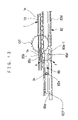
- FIG. 3 is a top view of the disk changer
- FIG. 4 is a left side view of FIG. 3 ;
- FIG. 5 is a sectional view taken along line P—P of FIG. 3 ;
- FIG. 6 is a top view showing the detail of a tray transfer unit
- FIG. 7 is an exploded perspective view showing a tray gear, unit and a tray driving unit
- FIG. 8 is a sectional view taken along line Q—Q of FIG. 6 ;
- FIGS. 9( a ) and 9 ( b ) are detail top views showing the positional relationship between the tray gear unit and the tray driving unit;
- FIGS. 10( a ) to 10 ( c ) are detail sectional views for explaining the relationship between the tray gear unit and the tray driving unit;
- FIG. 11 is a left side view showing the detail of a tray selecting unit 80 ;
- FIG. 12 is a left inside view showing a main part of FIG. 11 ;
- FIG. 13 is a top view showing the main part of FIG. 11 ;
- FIG. 14 is a to view showing the positional relationship between a disk recording/reproducing section and an elevating unit
- FIG. 15 is a top view sowing the detail of an elevating state of the disk recording/reproducing section
- FIGS. 16( a ) and 16 ( b ) are left side views of FIG. 15 ;
- FIG. 17 is a left side view of FIG. 14 ;
- FIG. 18 is a right side view of FIG. 14 ;
- FIG. 19 is a top view showing the detail of a driving mechanism
- FIG. 20 is a top view showing the detail of a main part of FIG. 19 ;
- FIGS. 21( a ) and 21 ( b ), are sectional views taken along line R—R of FIG. 20 ;
- FIG. 22 is a perspective view showing the relationship between a switching gear and a Geneva gear
- FIG. 23 is a top view of FIG. 22 ;
- FIG. 24 is a perspective view showing a main gear taken from the below;
- FIGS. 25( a ) and 25 ( b ) are detail views for explaining the states of the main gear
- FIGS. 26( a ) and 26 ( b ) are detail views for explaining the states of the main gear.
- FIGS. 27( a ) and 27 ( b ) show whole timing charts.
- FIG. 1 is a perspective view showing a characteristic full-open state of a disk changer according to the present invention.
- Reference numeral 1 denotes of five trays
- reference numeral 2 a denotes a disk of 12 cm
- reference numeral 2 b denotes a disk of 8 cm
- reference numeral 6 denotes an outer frame body of a product having the present device
- reference numeral 7 denotes a door.
- FIGS. 2( a ) to 2 ( f ) are schematic left side views for explaining the operation of disks in this device.
- Reference numeral 1 denotes five trays
- reference numeral 60 denotes a disk recording/reproducing section
- reference character X denotes an attaching/detaching position
- reference character Y denotes a standby position
- reference character Z denotes a recording/reproducing position.
- FIG. 2( a ) shows a RESET state. All the five trays 1 are stored and aligned with one another on the standby position Y.
- FIG. 2( b ) shows an exchanging state. It is found that the disks 2 a ( 2 b ) can be loaded or ejected by moving the trays 1 on specific addresses one by one to the attaching/detaching position X.
- FIG. 2( c ) shows a recording/reproducing state.
- the tray 1 on a specific address is moved to the recording/reproducing position Z and is stopped thereon, so that recording or reproduction is started on the disk 2 a ( 2 b ) on the tray 1 and the disk 2 a ( 2 b ) can be exchanged for each address before recording and reproduction.
- FIG. 2( d ) is an exchanging state during recording and reproduction. Except for the disk 2 a ( 2 b ) on the tray 1 during recording and reproduction, the trays 1 on all the other addresses are moved to the attaching/detaching position X for each address, so that the disks 2 a ( 2 b ) can be loaded or ejected.
- FIG. 2( e ) shows the full-open state of FIG. 1 . All the trays 1 are moved from the standby position Y to the attaching/detaching position X and the trays 1 are arranged like steps.
- FIG. 2( f ) shows a full-open state during recording and reproduction. All the trays 1 other than the tray during recording and reproduction are moved from the standby position Y to the attaching/detaching position X and all the trays 1 are arranged like steps at the attaching/detaching position X.
- FIG. 3 is a top view of a disk changer according to the embodiment of the present invention
- FIG. 4 is a left side view of FIG, 3
- FIG. 5 is a sectional view taken along line P—P of FIG. 3 .
- reference numeral 1 denotes trays each having a large diameter step 1 a and a small diameter step. 1 b on the upper surface.
- the disks 2 a and 2 b having different outside shapes can be loaded thereon.
- grooves 1 c are formed on both sides of the back
- a rack 1 d is formed on the left side
- a rack le is formed on the back of the left rear in parallel with the rack 1 d
- the rack 1 e having the same module as that of the rack 1 d
- a protruding rib if is formed on the left intermediate portion of the back.
- a switch cam 1 g is provided at the front of the lower stage of the rack 1 d
- recessed portions 1 h are formed which are shared as the rack 1 d.
- the five (a plurality of) trays 1 are separately arranged in parallel while being stacked substantially in a perpendicular direction (vertical direction), which is at right angles to the main surfaces of the disks 2 a and 2 b .
- the trays 1 are supported by guide ribs 3 a , which are provided inside on the right and left of a mechanical base 3 , and a left tray guide 4 and a right tray guide 5 , so that the trays 1 move substantially in a horizontal direction (lateral direction) which is in parallel with the main surfaces of the disks 2 a and 2 b .
- FIGS. 3 to 5 show that the tray 1 on the highest stage is located on the attaching/detaching position X.
- Reference numeral 6 denotes the outer frame body of the product having the present device.
- the door 7 is provided on the front side of the trays 1 located on the standby position Y.
- the door 7 rotates around a fulcrum positioned on the lower part.
- the door 7 is normally closed by energization of a door spring. 8 .
- the disk recording/reproducing section 60 is provided behind the trays located on the standby position Y.
- the disk recording/reproducing section 60 is supported by a left guide rib 3 b and a right guide rib 3 c , which are formed on the side of the mechanical base 3 , and is, moved in a perpendicular direction (vertical direction) by an elevating unit 70 , which will be discussed later.
- a driving mechanism 100 composed of a motor for driving each part, a gear line, and a detection switch, is provided, under the trays 1 located on the standby position Y.
- a tray selecting unit 80 for selecting a specified tray 1 and a tray driving unit 90 and a tray gear unit 40 , which serve as the tray selecting unit 80 and a tray transfer unit 50 , are provided outside the left side of the mechanical base 3 shown in FIG. 4 . Moreover, a top cover 9 is attached to the top of the mechanical base 3 to prevent dust and obtain stiffness.
- FIG. 6 is a top view showing the detail of the tray transfer unit 50
- FIG. 7 is an exploded perspective view showing the tray gear unit 40 and the tray driving unit 90
- FIG. 8 is a sectional view taken along line Q—Q of FIG. 6
- FIGS. 9( a ) and 9 ( b ) are detail top views showing the positional relationship between the tray gear unit 40 and the tray driving unit 90
- FIGS. 10( a ) to 10 ( c ) are detail sectional views showing the relationship between the tray gear unit 40 and the tray driving unit 90 .
- the tray gear unit 40 which is provided ahead of the left of the trays 1 located on the standby position Y, five (a plurality of) tray gears 41 are rotatably attached to the same shaft and tray gears 41 are held by gear holders 42 on the left tray guide 4 .
- the left tray guide 4 has guide ribs 4 a which are engaged with the groove 1 c of the tray 1 together with the guide rib 3 a of the mechanical base 3 in such a manner as to move the trays 1 in a horizontal direction (forward and backward direction).
- Each of the tray gears 41 has a gear 41 b formed on the outer circumference of a cylindrical part 41 a and six cams 41 c formed on the internal circumference by dividing the circumference into 6 equal portions.
- the tray gears 41 are stacked and are paired with the trays 1 . Since the tray gears 41 are separated from one another, independent rotations can be performed.
- the cam 41 c has chambered portions 41 d in three directions on the upper end and the lower end, and a concave portion 41 e formed in a lateral direction (rotating direction). Further, since the gear 41 b is engaged with the rack id formed on the left side of the tray 1 , the tray 1 is moved by rotating the tray gear 41 .
- the gear 41 b of the tray gear 41 and the rack 1 d of the tray 1 are disengaged from each other.
- the rack 1 e formed on the back of the left rear of the tray 1 is engaged with a gear 43 a of a load gear 43 , which is rotatably attached to an elevating base 10 .
- the tray 1 is moved from the position by rotating the load gear 43 .
- the gear 43 a of the load gear 43 is equal to the gear 41 b of the tray gear 41 in the module and the number of teeth.
- the tray switching lever 44 is rotatably attached to a shaft 10 a of the elevating base 10 via a hole 44 a and thus the tray switching lever 44 is rotated in the direction of arrow A ( FIG. 6 ) by a moving force applied to the rear of the tray 1 .
- the tray 1 having the protruding rib 1 f engaged with the, driving cam 44 b of the tray switching lever 44 is also held without moving back and forth.
- a tray driving gear 92 is fixed on the lower end of the outer circumference of a driving pipe 91 , and four return springs 93 and three third tray driving cams 94 are alternately attached thereon. Thereafter, a single second tray driving cam 95 is inserted and a first tray driving cam 96 is fixed on the upper end. Besides, the return springs 93 , the third tray driving cams 94 , and the second tray driving cam 95 can be rotated separately from the driving pipe 91 .
- the tray driving gear 92 has a gear 92 a on the lower end, a groove 92 b on the gear 92 a , and two driving cams 92 c shifted along a straight line from the rotational center to the outside taken from the top. Moreover, a protrusion 92 d is formed on the upper end with a width of 60° taken from the top.
- Each of the third tray driving cams 94 also has two driving cams 94 a shifted along a straight line from the rotational center to the outside taken from the top. On the upper end and the lower end, a protrusion 94 b with a width of 60° is formed on the same position taken from the top. Further, the second tray driving cam 95 also has two driving cams 95 a , shifted along a straight, line from the rotational center to the outside taken from the top. On the lower end, a protrusion 95 b is formed with a width of 60° taken from the top.
- each member is energized by the return springs 93 attached between the members so that the members rotate clockwise taken from the top.
- the adjacent protrusions 92 d , 94 b , and 95 b are stopped while making contact with one another as shown in FIG. 9( a ).
- the first tray driving cam 96 also have two driving cams 96 a shifted along a straight line from the rotational center to the outside taken from the top, and the driving cams 96 a and the driving cams 92 c of the tray driving gear 92 are fixed on the same position taken from the top.
- the driving cams 92 c , 94 a , 95 a , and 96 a each have chamfered surfaces 92 e , 94 c , 95 c , and 96 b of two directions on the upper ends and the lower ends and recessed portions 92 f , 94 d , 95 d , and 96 c in the lateral direction (rotating direction).
- the tray driving unit 90 is attached to a shaft 97 , which is fixed over a seat 3 d of the mechanical base 3 and a hole 4 b of the left tray guide 4 , via an inner diameter hole 91 c of the driving pipe 91 in such a way that the tray driving unit 90 can rotate and slide vertically.
- the tray driving unit 90 is inserted into the cylindrical part 41 a of the tray gear 41 in the tray gear unit 40 in such a way that the tray driving unit 90 can slide vertically.
- the gear 92 a of the tray driving gear 92 is rotated by the driving mechanism 100 , which will be discussed later, so that the tray 1 can be moved.
- the gear 92 a of the tray driving gear 92 is rotated by the driving mechanism 100 , which will be discussed later, so that the tray 1 can be moved.
- inducing correction can be made by the concave portion 41 e and the recessed portions 92 f , 94 d , 95 d , and 96 c .
- the six cams 41 c of the engaged tray gear 41 can be selected by vertically moving the tray driving cams 94 , 95 , and 96 and thus the tray 1 to be moved can be selected.
- Reference numeral 45 denotes an open switch lever in which a shaft 45 a is rotatably attached to a bearing hole 3 e of the mechanical base 3 and five cams 45 b are engaged with the switch cams 1 g provided on the lower stages of the racks 1 d of the five trays 1 .
- the cams 45 b rotate in the direction of arrow C–D.
- a lever 45 c is formed on the lower end of the open switch lever 45 .
- the lever 45 c is engaged with the open switch 46 provided on the mechanical base 3 and detects the position of the tray 1 moving back and forth.
- FIG. 11 is a left side view showing the detail of the tray selecting unit 80
- FIG. 12 is a left inside view showing a main part of FIG. 11
- FIG. 13 is a top view showing the main part of FIG. 11
- reference numeral 81 denotes a select guide which is attached to a T-shaped rib 3 f so as to slide vertically.
- the T-shaped rib 3 f is formed on the mechanical base 3 .
- a hook 81 a is formed which is engaged with the groove 92 b of the tray driving gear 92 and rotatably supports the tray driving gear 92 .
- a pin 81 b is formed on the rear end of the select guide 81 .
- Reference numeral 82 denotes a select rack which is attached to the guide rib 3 g of the mechanical base 3 so as to move vertically.
- a stepped cam 82 a provided on the front end is engaged with the pin 81 b of the select guide 81 .
- the select guide 81 is vertically moved by moving the select rack 82 back and forth and thus the engaged tray driving gear.
- 92 that is, the tray driving unit 90 is moved vertically so that the, tray 1 to be moved can be selected.
- a sensor rib 82 b and a rib 82 c are formed on the lower end of the select rack 82 .
- the sensor rib 82 b is engaged with a photosensor 83 provided on the mechanical base 3 and detects a position in the forward and backward directions.
- the rib 82 c is engaged with a bottom switch 84 provided on the mechanical base 3 and detects a position of origin in the forward and backward directions.
- a rack 82 d is formed on the lower back of the select rack 82 and is driven by the driving mechanism 100 , which will be discussed later, so as to move back and forth.
- Reference numeral, 85 denotes tray lock levers which are rotatably attached to a shaft 3 h of the mechanical base 3 via 1 a hole 85 a .
- the five tray lock levers 85 are stacked vertically and are paired with the trays 1 , respectively.
- a lock cam 85 b is provided on the front end of the tray lock lever 85 .
- the lock cam 85 b rotates in the direction of arrow E ( FIG. 13 ) so as to be engaged with the recessed portion 1 h formed on the tray 1 , thereby preventing the tray 1 from moving back and forth. Simultaneously, the displacement of the stopping position of the tray 1 in the forward and backward directions is corrected by induction on a chamfered portion 85 c formed on the front end of the tray lock lever 85 .
- a locking protrusion 85 d is provided on the back of the lock cam 85 b .
- the locking protrusion 85 d is engaged with cams 82 e - 1 to 82 e - 5 formed in five lines in parallel on the back of the select rack 82 , and the tray lock lever 85 is rotated in the direction of arrow F ( FIG. 13 ).
- a releasing protrusion 85 e provided on the rear end of the tray lock lever 85 is similarly engaged with cams 82 f - 1 to 82 f - 5 formed in five lines in parallel, and the tray lock lever 85 is rotated in the direction of arrow F ( FIG. 13 ), and thus the lock cam 85 b on the front end and the recessed portion 1 h of the tray 1 are disengaged from each other.
- FIG. 14 is a top view showing the positional relationship between the disk recording/reproducing section 60 and the elevating unit 70
- FIG. 15 is a top view showing the detail of an elevating state of the disk recording/reproducing section 60
- FIGS. 16( a ) and 16 ( b ) are left side views of FIG. 14 or FIG. 15
- FIG. 17 is a left side view of FIG. 14
- FIG. 18 is a right side view of FIG. 14 .
- the left sliding plate 61 and the right sliding plate 62 are attached on the elevating base 10 so as to move back and forth. Further, a pin 61 c formed on the rear end of the left sliding plate 61 is engaged with a cam hole 63 b formed on the left end of a connecting lever 63 , which is rotatably attached to a shaft 10 b of the elevating base 10 via a hole 63 a . A pin 62 a formed on the rear end of the right sliding plate 62 is engaged with a long hole 63 c formed on the right end of the connecting lever 63 . Thus, the left sliding plate 61 and the right sliding plate 62 are interlocked with each other and are moved via the connecting lever 63 .
- the left sliding plate 61 is normally held toward the rear of a portion where a click spring 61 d is engaged with a first tilting cam 10 c formed on the elevating base 10 .
- the small rack 61 b of the left sliding plate 61 and the gear 43 b of the load gear 43 have a gap and are not engaged with each other.
- engagement is made as the tray 1 is moved from the standby position Y to the recording/reproducing position Z, and the left sliding plate 61 is moved by the rotation of the load gear 43 .
- the left sliding plate 61 When the left sliding plate 61 is further moved forward, engagement of the left sliding plate 61 and the load gear 43 is shifted to engagement of a large rack 61 e and the gear 43 a . Thereafter, the large rack 61 e and the gear 43 a are disengaged from each other, and the left sliding plate 61 is held toward the front of a portion where the click spring 61 d is engaged with a second tilting cam 10 d formed on the elevating base 10 . Thus, it is possible to obtain a gap between the large, rack 61 e and the gear 43 a . Additionally, the load gear 43 has a lower gear 43 c driven by the driving mechanism 100 , which will be discussed later.
- Reference numeral 64 denotes a center detaching lever which is rotatably attached to a shaft 101 a via a hole 64 a to a shaft 101 a formed on a large pitch plate 101 of the driving mechanism 100 , which will be discussed later.
- the pin 64 b provided on the right end of the center detaching lever 64 is similarly engaged with a detaching cam 102 a on a main gear 102 of the driving mechanism 100 , which will be discussed later.
- a cam 64 c provided on the left end of the center detaching lever 64 is engaged with a pin 65 b provided on the inner end of an end detaching lever 65 .
- the end detaching lever 65 is rotatably attached to a shaft 10 e of the elevating base 10 via a hole 65 a.
- a cam 65 c formed on the outer end of the end detaching lever 65 is engaged with a square pin 61 f formed on the back when the left sliding plate 61 is moved forward. Therefore, the main gear 102 can control the movement of the left sliding plate 61 in the forward and backward directions.
- the pin 65 b of the end detaching lever 65 is formed with a long shape in a vertical direction so that engagement with the cam 64 c of the center detaching lever 64 can be maintained even when the pin 65 b is vertically moved by the elevating unit 70 , which will be discussed later.
- Reference numeral 66 denotes a recording/reproducing unit in which the disks 2 a and 2 b are held on the turntable 66 a before recording or reproduction.
- Pins 66 b and 66 c provided on the right and left sides are engaged with guide ribs 10 f and 10 g of the elevating base 10 , so that the recording/reproducing unit 66 is movably attached in a vertical direction.
- the single pin 66 b on the left side is engaged with an elevating cam 61 g of the left sliding plate 61
- the plurality of pins 66 c on the right side are engaged with an elevating cam 62 b of the right sliding plate 62 .
- the recording/reproducing unit 66 is vertically moved in response to the movement of the left sliding plate 61 and the right sliding plate 62 in the forward and backward directions.
- Reference numeral 67 denotes a clamper which is rotatably attached to a clamp plate 10 h of the elevating base 10 via a hole 10 i .
- the clamper 67 holds the disks 2 a and 2 b between the clamper 67 and the turntable 66 a of the recording/reproducing unit 66 by a magnetic force.
- rotation can be made while obtaining a gap from the hole 10 i.
- Reference numeral 68 denotes a clamp guide which is attached to the clamp plate 10 h of the elevating base 10 so as to move in the forward and backward directions.
- the clamp guide 68 has a tilting cam 68 a engaged with the damper 67 . At this point, when the clamp guide 68 is moved forward, the damper 67 is moved upward. When the clamp guide 68 is moved backward, the clamp guide 68 is disengaged from the damper 67 , and the damper 67 enters a free state and moves downward.
- the clamp guide 68 has a cam hole 68 b on the rear end that is engaged with a pin 63 e of the connecting lever 68 , and the clamp guide 68 is moved in the forward and backward directions in response to the rotation of the connecting lever 63 .
- reference numeral 71 denotes a left elevating rack 67 which is attached to a groove 3 i of the mechanical base 3 so as to move in the forward and backward directions
- reference numeral 73 denotes a right elevating rack which is attached to a groove 3 j of the mechanical base 3 so as to move in the forward and backward directions.
- An elevating connection lever 72 is provided between the elevating racks 71 and 73 , and the elevating connection lever 72 is rotatably attached to a shaft 101 b formed on a large pitch plate 101 of the driving mechanism 100 , which will be discussed later.
- a pin 71 a formed on the front end of the left elevating rack 71 is engaged with a cam hole 72 b formed on the left end of the elevating connection lever 72
- a pin 73 a formed on the front end of the right elevating rack 73 is engaged with a long hole 72 c formed on the right end of the elevating connecting lever 72 , so that the elevating racks 71 and 73 are moved in synchronization with each other.
- the left elevating rack 71 is moved forward to a certain degree or more, since the pin 71 a of the left elevating rack 71 is shifted to engagement with the long hole 72 d of the cam hole 72 b , the rotation of the elevating connection lever 72 is stopped and is kept in its state. Thus, only the left elevating rack 71 is further moved forward.
- pins 10 j and 10 k are engaged with the guide ribs 3 b and 3 c on the right and left of the mechanical base 3 so as to move vertically.
- the elevating base 10 is vertically moved by the movement of the left elevating rack 71 and the right elevating rack 73 in the forward and backward directions.
- a rack 71 c is provided under the left elevating rack 71 and is driven by the driving mechanism 100 , which will be discussed later.
- FIG. 19 is a top view showing the detail of the driving mechanism 100
- FIG. 20 is a top view showing the detail of a main part of FIG. 19
- FIGS. 21( a ) and 21 ( b ) are sectional views taken along line R—R of FIG. 20
- FIG. 22 is a perspective view showing the relationship between the switching gear 128 and a Geneva gear 131
- FIG. 23 is a top view of FIG. 22
- FIG. 24 is a perspective view showing the Geneva gear taken from the below.
- reference numeral 103 denotes a horizontal drive motor, which drives a driving gear 109 via a decelerating mechanism constituted by a motor pulley 104 , a belt 105 , a pulley gear 106 , a first reduction gear 107 , and a second reduction gear 108 .
- a main gear 102 is driven by driving the driving gear 109 .
- a gear 102 b provided around the lower part of the main gear 102 is constantly engaged with the driving gear 109 .
- a gear 102 c or 102 d provided partially around the upper surface of the main gear 102 is engaged with a small gear 110 a of a step-up gear 110 intermittently.
- a gear 102 e provided partially on the inside of the gear 102 c or 102 d is intermittently engaged with a small gear 111 a of an inverting gear 111 .
- the gear 102 c or 102 d and the small gear 110 a of the step-up gear 110 are not engaged with each other.
- the small gear 110 a of the step-up gear 110 and the large gear 111 b of the inverting gear 111 are constantly engaged with each other.
- the step-up gear 110 is configured so that only a rotation direction is different but a reduction ratio is equal in the case where the small gear 110 a is driven by the gear 102 c or 102 d and in the case where the small gear 110 a is driven by the large gear 111 b of the inverting gear 110 and the small gear 110 a is driven by engaging the small gear 111 a of the inverting gear 111 with the gear 102 e.
- the step-up gear 110 drives and rotates the gear 92 a of the tray gear 92 in the tray driving unit 90 via an relay gear constituted by a first relay gear 112 , a second relay gear 113 , a large gear 114 a of a front crown gear 114 , and a tray relay gear 115 on a part where the tray relay gear 115 is constantly engaged.
- the tray relay gear 15 is formed as a long gear in a vertical direction so that engagement is maintained even when the tray driving gear 92 is moved vertically.
- a crown gear 114 b of the front crown gear 114 drives and rotates the lower gear 43 c of the load gear 43 in the disk recording/reproducing section 60 via a relay gear constituted by a timing gear 116 , a crown gear 117 a and a large gear 117 b of a rear crown gear 117 , and a load relay gear 118 on a part where the load relay gear 118 is constantly engaged.
- the load relay gear 118 is formed as a long gear in a vertical direction so that engagement is maintained even when the load gear 43 is moved vertically.
- Reference numeral 119 denotes a step-up lock lever which is rotatably attached to a shaft 101 c of a large pitch plate 101 via a hole 119 a .
- a cam 119 b on one end of the speed up lock lever 119 is engaged with the lock cam 110 c of the step-up gear 110 to specify the stopping position of the step-up gear 110 .
- a pin 119 c on the other end of the speed up lock lever 119 is engaged with lock cams 102 f and 102 g provided on the main gear 102 , and the main gear 102 controls the intermittence of specification of a stopping position of the step-up gear 110 .
- a spring part 119 d is in contact with a rib 110 d of a large pitch plate 101 and thus the step-up lock lever 119 is energized so as to rotate in the direction of arrow G ( FIG. 19 ).
- Reference numeral 120 denotes an elevation driving motor which drives a branch gear 126 via a decelerating mechanism constituted by a motor pulley 121 , a belt 122 , a pulley gear 123 , a third reduction gear 124 , and a fourth reduction gear 125 .
- a select driving gear 127 is driven where a small gear 126 a of the branch gear is engaged, and a rack 82 d of the select rack 82 is driven on the tray selecting unit 80 where the select driving gear 127 is constantly, engaged, so that the select rack 82 is moved in the forward and backward directions.
- a large gear 126 b of the branch gear 126 is engaged with a small gear 128 a of a switch gear 128 and drives and rotates the switching gear 128 .
- the switching gear 128 is attached to a shaft 129 fixed between the mechanical base 3 and the large pitch plate 101 so as to rotate and move in a vertical direction.
- a guide 130 b of a switching lever 130 is engaged with a groove 128 b formed on the switching gear 128 .
- the switching lever 130 is rotatably attached to a bearing 3 k of the mechanical base 3 via a shaft 130 a.
- a pin 130 provided on the other end of the switch lever 130 is engaged with the a driving cam 102 h provided on the main gear 102 , and the driving cam 102 h is vertically moved by the rotation of the main gear 102 , so that the switching lever 130 rotates about the shaft 130 a in the direction of arrow I–J ( FIG. 21 ).
- the switching gear 128 is moved vertically.
- the small gear 128 a is formed with a long shape in the vertical direction so that engagement with the large gear 126 b of the branch gear 126 is maintained even when the switching gear 128 is moved vertically.
- a circular arc cam 131 b is formed between the cam grooves 131 a .
- the circular arc cam 131 b is engaged with the cylindrical part 128 d of the switching gear 128 , so that locking is made to prevent rotation when there is no need for rotation.
- the circular arc cams 131 b are formed so that both ends slightly spread wider than the arc.
- the cam groove 131 a of the Geneva gear 131 has a chamfered part 131 d so that the cam groove 131 a increases in width as it is closer to the end 131 c .
- the gear 131 e of the Geneva gear 131 is engaged with an elevating driving gear 132 to drive the elevating driving gear 132 .
- the rack 71 c is driven on the left elevation rack 71 of the elevating unit 70 which is constantly engaged with the elevating driving gear 132 , and thus the left elevating, rack 71 is moved in the forward and backward directions.
- the above-described switching gear 128 , the Geneva gear 131 , and so on constitute an example of a connecting/disconnecting unit 140 for connecting and disconnecting transmission on a part in a transmission line from the elevation driving motor 120 to the elevating unit 70 .
- the connecting/disconnecting unit 140 is driven by the switching lever 130 which operates in response to rotation of the main gear 102 interlocked with the horizontal drive motor 103 .
- a stock switch 133 and a play switch 134 are located on a part of the mechanical base 3 below the back of the main gear 102 .
- the stock switch 133 and the play switch 134 are engaged with a stock cam 102 i and a play cam 102 j formed on the back of the main gear 102 , so that the rotating position of the main gear 102 is detected.
- the components of the driving mechanism 100 are attached to and held by the mechanical base 3 , the large pitch plate 101 , and the small pitch plate 135 .
- the horizontal drive motor 103 , the elevation driving motor 120 , the open switch 46 , the photosensor 83 , the bottom switch 84 , the stock switch 133 , and the play switch 134 are attached to a printed board 136 , are connected to one another, and are held.
- FIGS. 25 and 26 are detail drawings for explaining the state of the main gear 102 , ad FIGS. 27( a ) and 27 ( b ) show whole timing charts.
- the elevation driving motor 120 of the driving mechanism 100 rotates in CCW direction ( FIG. 19 ) and drives the branch gear 126 via the decelerating mechanism.
- the select driving gear 127 engaged with a small gear 126 a of the branch gear 126 is driven.
- the rack 82 d of the select rack 82 on the tray selecting unit 80 is driven on a part which is constantly engaged with the select driving gear 127 , so that the select rack 82 is moved forward.
- the movement of the select rack 82 disengages the rib 82 c from the bottom switch 84 and turns off the bottom switch 84 . Subsequently, when the select rack 82 is further moved forward, the pin 81 b is driven by the stepped cam 82 a of the select rack 82 and the select guide 81 is moved upward. Thus, the tray driving unit 90 is also moved upward with respect to the hook 81 a of the select guide 81 . The tray driving unit 90 is engaged via the groove 92 b of the tray driving gear 92 .
- the sensor rib 82 b is detected by the photosensor 83 .
- stopping is made on a position where the cam 41 c of the tray gear 41 on the highest stage in the tray gear unit 40 and the driving cam 96 a of the first tray driving cam 96 in the tray driving unit 90 are equal in height, that is, at U shown in FIG. 27( a ).
- the switch gear 128 having the small gear 128 a engaged with the large gear 126 b of the branch gear 126 is driven.
- the main gear 102 is in the state of FIG. 25( a ), and the pin 130 c of the switching lever 130 is engaged with a part where the driving cam 102 h is positioned above.
- the switching lever 130 rotates about the shaft 130 a in the direction of arrow I ( FIG. 21) . Therefore, as shown in FIG. 21( a ) and FIG. 22 , the switching gear 128 is moved downward and the driving pin 128 c of the switch gear 128 is, engaged with the cam groove 131 a of the Geneva gear 131 , and thus the Geneva gear 131 is driven and is intermittently rotated.
- the elevating driving gear 132 engaged with the Geneva gear 131 is driven, the rack 71 c of the left elevating rack 71 in the elevating unit 70 is driven, the elevating unit 70 being constantly engaged with the elevating driving gear 132 , the left elevating rack 71 is moved forward, and the right elevating rack 73 interlocked via the elevating connection lever 72 is moved to the rear. Then, since the pins 10 j and 10 k of the elevating base 10 are driven by the stepped cam 71 b of the left elevating rack 71 and the stepped cam 73 b of the right elevating rack 73 , the disk recording/reproducing section 60 is also moved upward and is stopped at the position suited to the height of the tray 1 located on the highest stage.
- the locking protrusion 85 d is engaged with the cams 82 e - 2 to 82 e - 5 of the select rack 82 and rotates in the direction of arrow E ( FIG. 13 ).
- the lock cam 85 b is engaged with the recessed portion 1 h of the tray 1 to prevent the tray 1 from moving in the forward and backward directions.
- a releasing protrusion 85 e is engaged with the cam 82 f - 1 of the select rack 82 and rotates in the direction of arrow F ( FIG. 13 ).
- the lock cam 85 b and the recessed portion 1 h of the tray 1 are not engaged with each other and the tray 1 can move in the forward and backward directions.
- the horizontal drive motor 103 of the driving mechanism 100 rotates in the direction of CW ( FIG. 19 ) and drives the driving gear 109 via the decelerating mechanism.
- the man gear 102 is driven which is constantly engaged with the driving gear 109 .
- the main gear 102 is in the state of FIG. 25( a ) when the tray 1 is on the standby position Y.
- the lock cam 102 f firstly presses the pin 119 c to rotate the step-up, lock lever 119 in the direction of arrow H ( FIG. 19 ) which is opposite from the energization force of the spring 119 d part.
- the cam 119 b and the lock cam 110 c of the step up gear 110 are disengaged from each other and the step-up gear 11 can rotate.
- the gear 102 d of the main gear 102 is engaged with the gear 102 d of the main gear 102 and the step-up gear 110 is rotated, so, that the tray driving gear 92 of the tray driving unit 90 is rotated via thee relay gear.
- the first tray driving cam 96 fixed on the driving pipe 91 is also rotated simultaneously together with the tray driving gear 92 and the driving cam 96 a drives the cam 41 c of the tray gear 41 to rotate the tray gear 41 , so that the tray 1 on the highest stage is moved forward.
- the driving cam 102 h is shifted from the upward direction to the downward direction in response to the rotation of the main gear 102 , so that the switching lever 130 where the pin 130 c is engaged is rotated about the shaft 130 a in the direction of arrow J ( FIG. 21 ).
- the switching gear 128 is moved upward as shown in FIGS. 21( b ) and 23 . Since the driving pin 128 c of the switching gear 128 and the cam grooves 131 a of the Geneva gear 131 are disengaged with each other because gaps are formed above and below. However, the cylindrical part 128 d of the switching gear 128 and the circular arc cam 131 b of the Geneva gear 131 maintain the engagement.
- the switch cam 19 of the tray 1 is engaged with the cam 45 b to rotate the open switch lever 45 in the direction of arrow C ( FIG. 6 ) and the lever 45 c turns on the open switch 46 , the movement is stopped.
- the tray 1 on the highest stage is located on the attaching/detaching position X as shown in FIGS. 3 to 5 and OPEN 5 (b- 5 ) of FIG. 2( b ).
- the main gear 102 is in the state of FIG. 25( b ), and the stock switch 133 and the play switch 134 that are engaged with the main gear 102 are in the state U shown in FIG. 27( b ).
- the cams other than the driving cam 96 a of the first tray driving cam 96 that is, the driving cam 92 c of the tray driving gear 92 , the driving cam 94 a of the third tray driving cam 94 , and the driving cam 95 a of the second tray driving cam 95 are not engaged with any of the five cams 41 c of the tray gear 41 without interference.
- the former value and the latter value are not limited to the above values. Other values are acceptable as long as the former value is smaller than the latter value and driving cams other than the driving cam 96 a are not engaged with the cams of tray gears other than the tray gear 41 when the driving cam 96 a on the top is engaged with the cam 41 c of the tray gear 41 . Further, instead of such a configuration, the following lamination is also acceptable an interval between the driving cam on the lowest stage and the driving cam in the previous stage is shorter than those of the other driving cams.
- the elevating unit 70 is not moved because the elevating unit 70 is locked by engagement of the cylindrical part 128 d of the switching gear 128 and the circular arc cam, 131 b of the Geneva gear 131 where the left elevating rack 71 is engaged via the elevating driving gear 132 .
- the disk recording/reproducing section 60 is not deviated in height.
- the horizontal drive motor 103 of the driving mechanism 100 is rotated in the opposite direction from moving the tray 1 from the standby position Y to the attaching/detaching position X, that is, in CCW direction ( FIG. 19 ).
- the main gear 102 is rotated in the direction of arrow L ( FIG. 19 ) via, the decelerating mechanism and the driving gear 109 , the tray 1 is moved to the rear, and thus the tray 1 returns to the standby position Y and stops thereon as indicated by RESET of FIG. 2( a ).
- step-up lock lever 119 and the main gear 102 also return to the state of FIG. 25( a ) and the switching gear 128 and the switching lever 130 return to the states of FIGS. 21( a ) and 22 , so that the main gear 102 and the step-up gear 110 are temporarily disengaged.
- the main gear 102 since the horizontal drive motor 103 keeps rotating in CCW direction ( FIG. 19) , the main gear 102 further rotates in the direction of arrow L.
- the lock cam 102 f presses the pin 119 c again and rotates the step-up lock lever 119 in the direction of arrow H ( FIG. 19 ) which is opposite from the energization force of the spring part 119 d .
- the cam 119 b and the lock cam 110 c of the step-up gear 110 are disengaged with each other and the step-up gear 110 can rotate.
- the gear 102 c of the main gear 102 is engaged with the small gear 110 a of the step-up gear 110 and thus the step-up gear 110 is rotated in the opposite direction from moving the tray 1 from the standby position Y to the attaching/detaching position X.
- the tray driving gear 92 of the tray driving unit 90 , the first tray driving cam 96 , and the tray gear 41 also rotate backward and thus the tray 1 on the highest stage starts moving to the rear.
- the switching lever 130 where the pin 130 c is engaged is rotated about the shaft 130 a in the direction of arrow J ( FIG. 21 ), the switching gear 128 is moved upward as shown in FIGS. 21( b ) and 23 , and the driving pin 128 c of the switching gear, 128 and the cam grooves 131 a of the Geneva gear 131 are disengaged because gaps are formed above and below.
- the cylindrical part 128 d of the switching gear 128 and the circular arc cams 131 b the Geneva gear 131 maintains the engagement.
- the gear 41 b of the tray gear 41 and the rack 1 d of the tray 1 are disengaged from each other.
- the rack 1 e on the back of the left rear of the tray 1 is simultaneously engaged with the gear 43 a of the load gear 43 .
- the lower gear 43 c is constantly engaged with the step-up gear 110 via the relay gear and is rotated in synchronization with the tray gear 41 .
- the tray 1 is subsequently moved to the rear. Thereafter, although the tray gear 41 keeps rotating, interference does not occur because the gear 41 b and the rack id of the tray 1 are disengaged from each other.
- the tray switching lever 44 is held so as not to be rotated because of the engagement of the pin 44 c and the L-shaped cam 61 a of the left sliding plate 61 which has moved forward, the tray 1 having the protrusion rib 1 f engaged with the driving cam 44 b of the tray switching lever 44 is also held without being moved in the forward and backward directions.
- the left sliding plate 61 is further moved forward, the right sliding plate 62 interlocked via the connecting lever 63 is moved to the rear, and the elevating cam 61 g of the left sliding plate 61 and the elevating cam 62 b of the right sliding plate 62 drive the pins 66 b and 66 c of the recording/reproducing unit 66 .
- the recording/reproducing unit 66 moves upward.
- the disk 2 a ( 2 b ) loaded on the step 1 a ( 1 b ) of the tray 1 is held on the turntable 66 a together with the clamper 67 and thus the state of FIG. 16( b ) is provided which permits the disk 2 a ( 2 b ) to rotate.
- the square pin 65 f on the back drives the cam 65 c of the end detaching lever 65 and rotates the end, detaching lever 65 in the direction of arrow K ( FIG. 14 ).
- a detaching cam 102 a of the main gear 102 rotates the center detaching lever in the direction of arrow M ( FIG. 14 ).
- the engaged end detaching lever 65 further rotates in the direction of arrow K ( FIG. 14 ) to permit the cam 65 c to sandwich the square pin 61 f and thus the left sliding plate 61 further moves forward.
- the large rack 61 e and the gear 43 a are disengaged from each other and the left sliding plate 61 is held while being located toward the forward direction on a part where the click spring 61 d is engaged with the second tilting cam 10 d of the elevating base 10 .
- the large rack 61 e and the gear 43 a are disengaged from each other and the left sliding plate 61 is held while being located toward the forward direction on a part where the click spring 61 d is engaged with the second tilting cam 10 d of the elevating base 10 .
- the main gear 102 is in the state of FIG. 26( a ), and the stock switch 133 and the play switch 134 that are engaged with the main gear 102 are in state V of FIG. 27( b ).
- the switching gear 128 is moved upward, the driving pin 128 c of the switching gear 128 and the cam grooves 131 a go out of engagement because gaps are formed above and below.
- the cylindrical part 128 d of the switching gear 128 and the circular arc cam 131 b of the Geneva gear 131 maintains the engagement. Therefore, the elevating unit 70 having the elevating rack 71 engaged with the Geneva gear 131 via the elevating driving gear 132 is locked without being moved even when vibration or impact is applied from the outside, and thus the disk recording/reproducing section 60 is not deviated in height.
- the gear 102 c of the main gear 102 is engaged with the small gear 110 a of the step-up gear 110 , and the step-up gear 110 rotates opposite to the above direction (when the tray 1 is moved from the standby position Y to the recording/reproducing position Z).
- the load gear 43 , the tray driving gear 92 of the tray driving unit 90 , the first tray driving cam 96 , and the tray gear 41 also rotate backward.
- the left sliding plate 61 is moved to the rear by the rotation of the load gear 43 .
- the pin 61 c of the left sliding plate 61 drives the cam hole 63 b of the connecting lever 63 and thus the right sliding plate 62 interlocked via the connecting lever 63 is moved forward.
- the recording/reproducing unit 66 is moved in the downward direction which is opposite from the above direction (when the tray 1 is moved from the standby position Y to the recording/reproducing position Z).
- the disk 2 a ( 2 b ) is returned to the step 1 a ( 1 b ) of the tray 1 and the pin 63 e simultaneously drives the cam hole 68 b in response to the rotation of the connecting lever 63 .
- the clamp guide 68 is moved forward, and the tilting cam 68 a on the front end is engaged with the damper 67 to move the damper 67 upward.
- the tray switching lever 44 rotates in the direction of arrow B ( FIG. 6 ) to drive the protruding rib if on the back of the tray 1 where the driving cam 44 b is engaged.
- the tray 1 starts moving in a forward direction.
- the rack le on the back of the left rear of the tray 1 is engaged with the gear 43 a of the load gear 43 and thus the tray 1 further moves forward.
- the left sliding plate 61 moves backward when the small rack 61 b and the gear 43 b of the load gear 43 are disengaged from each other and the click spring 61 d is engaged with the first tilting cam 10 c of the elevating base 10 .
- the left sliding plate 61 is stopped in a state in which a gap is obtained between the small rack 61 b , and the gear 43 b of the load gear 43 .
- the L-shaped cam 61 a and the pin 44 c of the tray switching lever 44 are engaged with each other, so that the tray switching lever 44 is held so as not to be rotated.
- the tray 1 returns to the standby position Y and stops thereon as indicated by RESET of FIG. 2( a ).
- the step-up lock lever 119 and the main gear 102 also return to the state of FIG. 25( a ) and the switching gear, 128 and the switching lever 130 also return to the states of FIGS. 21( a ) and 22 , so that the main gear 102 and the step-up gear 110 are disengaged from each other.
- the rotations of the load gear 43 , the tray driving gear 92 of the tray driving unit 90 , the first tray driving cam 96 , and the tray gear 41 are also stopped.
- the elevation driving motor 120 of the driving mechanism 100 rotates in CW direction ( FIG. 19 ) which is opposite from the above direction and drives the branch gear 126 via the decelerating mechanism.
- the select driving gear 127 engaged with the small gear 126 a of the branch gear 126 is driven and the rack 82 d of the select rack 82 in the tray selecting unit 80 is driven on a part which is constantly engaged with the select driving gear 127 , so that the select rack 82 is moved backward.
- the switching gear 128 is simultaneously driven in which the large gear 126 b of the branch gear 126 and the small gear 128 a are engaged with each other.
- the driving pin 128 c of the switching gear 128 is engaged with the cam groove 131 a of the Geneva gear 131 to drive the Geneva gear 131 and makes rotation intermittently.
- the elevating driving gear 132 engaged with the Geneva gear 131 is driven, the rack 71 c of the left elevating rack 71 in the elevating unit 70 is driven on apart which is constantly engaged with the elevating driving, gear 132 , the left elevating rack 71 is moved backward, and the right elevating rack 73 interlocked via the elevating connecting lever 72 is moved forward at the same time.
- the pins 10 j and 10 k of the elevating base 10 are driven by the stepped cam 71 b of the left elevating rack 71 and the stepped cam 73 b of the right elevating rack 73 .
- the disk recording/reproducing section 60 is also moved downward and stopped at a position suited to the height of the tray 1 on the lowest stage.
- the locking protrusion 85 d is engaged with the cams 82 e - 1 to 82 e - 4 of the select rack 82 and rotates the tray lock lever 85 in the direction of arrow E ( FIG. 13 ).
- the lock cam 85 b is engaged with the recessed portion 1 h of the tray 1 to prevent the tray 1 from moving in the forward and backward directions.
- the releasing protrusion 85 e is engaged with the cam 82 f - 5 of the select rack 82 and rotates the tray lock lever 85 in the direction of arrow F ( FIG. 13 ).
- the lock cam 85 b and the recessed portion 1 h of the tray 1 are not engaged with each other, and the tray 1 can move in the forward and backward directions.
- the horizontal drive motor 103 of the driving mechanism 100 rotates in the direction of CW ( FIG. 19 ), and as described above, the horizontal drive motor 103 moves the tray 1 on the lowest stage to the attaching/detaching position X and stops the tray 1 thereon as indicated by OPEN 1 (b- 1 ) of FIG. 2( b ).
- the disk 2 a ( 2 b ) can be loaded on the step 1 a ( 1 b ) of the tray 1 on the lowest stage.
- the elevation driving motor 120 of the driving mechanism 100 rotates in CW direction ( FIG. 19 ) and is stopped by the similar operation at a position where the cam 41 c of the tray gear 41 on the third stage in the tray gear unit 40 is equal in height to the driving cam 96 a of the first tray driving cam 96 in the tray driving unit 90 , that is, at W of FIG. 27( a )as shown in FIG. 10( c ).
- the switching gear 128 is similarly driven by the branch gear 126 . Since the switching gear 128 is moved downward as shown in FIG. 21( a ), the driving pin 128 c of the switching gear. 128 is engaged with the cam groove 131 a of the Geneva gear 131 to drive and rotate the Geneva gear 131 intermittently. Thus, the disk recording/reproducing section, 60 is also moved downward by the similar operation and is stopped at a place suited to the height of the tray 1 on the third stage.
- the locking protrusion 85 d is engaged with the cams 82 e - 1 and 82 e - 2 and 82 e - 4 and 82 e - 5 of the select rack 82 and rotates the tray lock lever 85 in, the direction of arrow E ( FIG. 13 ).
- the lock cam 85 b is engaged with the recessed portion 1 h of the tray 1 to prevent the tray 1 from moving in the forward and backward directions.
- the releasing protrusion 85 e is engaged with the cam 82 f - 3 of the select rack 82 and rotates the tray lock lever 85 in the direction of arrow F ( FIG. 13 ).
- the lock cam 85 b and the recessed portion 1 h of the tray 1 are not engaged with each other and the tray 1 can move in the forward and backward directions.
- the horizontal drive motor 103 of the driving mechanism 100 rotates in CCW direction ( FIG. 19 ) and moves the tray 1 to the recording/reproducing position Z and stops the tray 1 thereon as indicated by DISC(c- 3 ) of FIG. 2 ⁇ , and recording and reproduction are started on the disks 2 a ( 2 b ) on the tray 1 of the third stage.
- the disks 2 a ( 2 b ) on the trays 1 of all the other addresses are moved to the attaching/detaching position X for each address without interrupting the recording/reproduction, and the disks 2 a ( 2 b ) are loaded or ejected (corresponding to. FIG. 2( d )).
- the disks 2 a ( 2 b ) are loaded or ejected (corresponding to. FIG. 2( d )).
- the elevation driving motor 120 of the driving mechanism 100 rotates in CCW direction ( FIG. 19) and drives the branch gear 126 via the decelerating mechanism.
- the select driving gear 127 engaged with the small gear 126 a of the branch gear, 126 is driven, and the rack 82 d of the select rack 82 in the tray selecting unit 80 is driven at a place which is constantly engaged with the select driving gear 127 , so that the select track 82 is moved forward.
- the tray driving unit 90 where the hook 81 a and the groove 92 b of the tray driving gear 92 are engaged is also moved upward.
- the sensor rib 82 b is detected by the photosensor 83 , and as shown in FIG. 10( a ), stopping is made at a position where the cam 41 c of the tray gear 41 on the highest stage in the tray gear unit 40 is equal in height to the driving cam 96 a of the first tray driving cam 96 in the tray driving unit 90 , that is, at U of FIG. 27( a ).
- the switching gear 128 where the large gear 126 b and the small gear 128 a of the branch gear 126 are engaged is driven at the same time.
- the switching gear 128 is moved upward as shown in FIG. 21( b ), and the driving pin 128 c of the switching gear 128 and the cam grooves 131 a of the Geneva gear 131 have gaps above and below without engagement.
- the Geneva gear 131 remains stopped without rotation.
- the rack 71 c of the left elevating rack 71 in the elevating unit 70 also remains stopped and the elevating unit 70 is not moved, and thus the disk recording/reproducing section 60 is held at the height of the tray 1 on the lowest stage, so that recording/reproduction of the disk 2 a ( 2 b ) is maintained.
- the elevating unit 70 having the left elevating rack 71 engaged with the Geneva gear 131 via the elevating driving gear 132 is locked so that the elevating unit 70 does not move even when vibration or impact is applied from the outside. Hence, the disk recording/reproducing section 60 is not deviated in height.
- the locking protrusion 85 d is engaged with the cams 82 e - 2 to 82 e - 5 of the select rack 82 and rotates the tray lock lever 85 in the direction of arrow E ( FIG. 13 ).
- the lock cam 85 b is engaged with the recessed portion 1 h of the tray 1 to prevent the tray 1 from moving in the forward and backward directions.
- the releasing protrusion 85 e is engaged with the cam 82 f - 1 of the select lock 82 and rotates the tray lock lever 85 in the direction of arrow F ( FIG. 13 ).
- the lock cam 85 b and the recessed portion 1 h of the tray 1 are not engaged with each other, and the tray 1 can move in the forward and backward directions.
- the main gear 102 rotates in the direction of arrow. L ( FIG. 19 ) via the decelerating mechanism and the driving gear 109 from the state of the FIG. 23 ⁇ .
- the lock cam 102 g presses the pin 119 c and rotates the step-up lock lever 119 in the direction of arrow H ( FIG. 19 ) which is opposite from energization of the spring part 119 d .
- the cam 119 b and the lock cam 110 c of the step-up gear 110 are disengaged from each other, so that the step-up gear 110 can rotate.
- the gear 102 e of the main gar 102 is engaged with the small gear 111 a of the inverting gear 111 where the small gear 110 a and the large gear 111 b of the step-up gear 110 are constantly engaged, and the inverting gear 111 and the step-up gear 110 are rotated.
- the tray driving gear 92 of the tray driving unit 90 , the first tray driving cam 96 , and the tray gear 41 are also rotated via the relay mechanism, so that the tray 1 on the highest stage is moved forward.
- the load gear 43 also rotates at the same time, the load gear 43 is disengaged from the tray 1 on the lowest stage at the recording/reproducing position Z, resulting in no interference.
- step-up gear 110 is driven from the main gear 102 via the inverting gear 111 , even when the main gear 102 rotates in the direction of arrow L ( FIG. 19 or 25 ), the tray 1 is moved forward.
- the switch cam 1 g of the tray 1 is engaged with the cam 45 b to rotate the open switch lever 45 in the direction of arrow C ( FIG. 6 ) and the, lever 45 c presses and turns on the open switch 46 , the movement is stopped.
- OPEN 5 (d- 5 ) of FIGS. 5 and 2( d ) the tray 1 on the highest stage is located on the attaching/detaching position X.
- the main gear 102 enters the state of FIG. 26( b ), and the stock switch 133 and the play switch 134 that are engaged with the main gear 102 enter the state W of FIG. 27( b ).
- the disk 2 a ( 2 b ) can be loaded or ejected on the step 1 a ( 1 b ) of the highest stage.
- the horizontal drive motor 103 of the driving mechanism 100 rotates in CW direction ( FIG. 19 )
- the main gear 102 rotates in the direction of arrow K ( FIG. 19 ) via the decelerating mechanism and the driving gear 109 . Therefore, the inverting gear 111 and the step-up gear 110 also rotate in the opposite direction.
- the tray driving gear 92 of the tray driving unit 90 , the first tray driving cam 96 , and the tray gear 41 also rotate in the opposite direction via the relay mechanism, and thus the tray 1 on the highest stage is moved backward, is returned to the standby position Y, and is stopped thereon. Then, the step-up lock lever 119 and the main gear 102 also return to the state of FIG. 26( a ), and the main gear 102 and the inverting gear 111 are also disengaged from each other.
- the elevation driving motor 120 of the driving mechanism 100 rotates in CW direction ( FIG. 19 ), and the select rack 82 is moved backward in the opposite direction by the similar operation.
- stopping is made at a position where the cam 41 c of the tray gear 41 on the third stage in the tray gear unit 40 is equal in height to the driving cam 96 a of the first tray driving cam 96 in the tray driving unit 90 , that is, at W of FIG. 27( a ).
- the locking protrusion 85 d is engaged with the cams 82 e - 1 and 82 e - 2 and 82 e - 4 and 82 e - 5 of the select track 82 , and rotates the tray lock lever 85 in the direction of arrow E ( FIG. 13 ).
- the lock cam 85 is engaged with the recessed portion 1 h of the tray 1 to prevent the tray 1 from moving in the forward and backward directions.
- the tray lock lever 85 on the third stage has the releasing protrusion 85 e engaged with the cam 82 f - 3 of the select rack 82 and rotates the tray lock lever 85 in the direction arrow F.( FIG. 13 ).
- the lock cam 85 b and the recessed portion 1 h of the tray 1 are not engaged with each other, and the tray 1 on the third stage can move in the forward and backward directions.
- the tray 1 on the third stage is moved forward by the similar operation. As indicated by OPEN 3 (d- 3 ) of FIG. 2( d ), the tray 1 on the third stage is located on the attaching/detaching position X. Besides, the switching gear 128 similarly stays upward as shown in FIG. 21( b ). Then, the disk 2 a ( 2 b ) can be loaded or ejected on the step 1 a ( 1 b ) of the tray 1 on the third stage.
- the elevation driving motor 120 of the driving mechanism 100 rotates in CCW direction ( FIG. 19 ) and the branch gear 126 is driven via the decelerating mechanism.
- the select driving gear 127 engaged with the small gear 126 a of the branch gear 126 is driven, the rack 82 d of the select rack 82 in the tray selecting unit 80 is driven, and the select rack 82 is moved forward.
- the movement of the select rack 82 permits the rib 82 c and the bottom switch 84 to be disengaged from each other and the bottom switch 84 is turned off. Then, when the select rack 82 moves forward, the pin 81 b is driven by the stepped cam 82 a of the select rack 82 to move the select guide 81 upward, and thus the tray driving unit 90 engaged via the groove 92 b of the tray driving gear 92 is also moved upward with respect to the hook 81 a of the select guide 81 .
- the sensor rib 82 b is detected by the photosensor 83 .
- stopping is made at a position where the cams 41 c of the tray gears 41 on all the stages in the tray gear unit 40 are equal in height to the driving cam 92 c of the corresponding tray driving gear 92 in the tray driving unit 90 and the driving cams 94 a and 95 a of the tray driving cams 94 and 95 , that is, at A of FIG. 27( a ).
- the first tray driving cam 96 is located on a non-active position above.
- the switching gear 128 is driven where the large gear 126 b and the small gear 128 a of the branch gear 126 are engaged.
- the main gear 102 is in the state of FIG. 25( a ). Since the place where the driving cam 102 h is positioned upward is engaged with the pin 130 c of the switching lever 130 , the switching lever 130 rotates about the shaft 130 a in the direction of arrow I ( FIG. 21) . Therefore, the switching gear 128 is moved downward as shown in FIGS. 21( a ) and 22 and the driving pin 128 c of the switching gear 128 is engaged with the cam groove 131 a of the Geneva gear 131 , and thus the Geneva gear 131 is driven and rotated intermittently.
- the elevating driving gear 132 engaged with the Geneva gear 131 is driven, the rack 71 c of the left elevating rack 71 is driven in the elevating unit 70 which is constantly engaged with the elevating driving gear 132 , the left elevating rack 71 is moved forward, and the right elevating rack 73 interlocked via the elevating connecting lever 72 is simultaneously moved to the rear.
- the stepped cam 71 b of the left elevating rack 71 and the stepped cam 73 b of the right elevating rack 73 drive the pins 10 j and 10 k of the elevating base 10 .
- the disk recording/reproducing section 60 also moves upward, and the movement of the elevating connecting lever 72 and the right elevating rack 73 is completed at a place suited to the tray 1 on the highest stage.
- Only the left elevating rack 71 further moves forward in accordance with an amount of movement of the select rack 82 from U of FIG. 27( a ) to A of FIG. 27( a ), so that no interference occurs even when the select rack 82 and the left elevating rack 71 are connected in each gear line.
- the stepped cam 71 b of the left elevating rack 71 is flat during this period, the disk recording/reproducing section 60 is not changed in height.
- the releasing protrusions 85 e - 1 to 85 e - 5 are engaged with the cams 82 f - 1 to 82 f - 5 of the select track 82 and rotate in the direction of arrow F ( FIG. 13 ).
- the lock cam 85 b and the recessed portion 1 h of the tray 1 are not engaged with each other and thus all the trays 1 can move in the forward and backward directions.
- the horizontal drive motor 103 of the driving mechanism 100 rotates in CW direction ( FIG. 17 ) and drives the driving gear 109 via the decelerating mechanism.
- the main gear 102 is driven which is constantly engaged with the driving gear 109 .
- the main gear 102 is in the state of FIG. 25( a ) when the tray 1 is located on the standby position Y.
- the lock cam 102 f firstly presses the pin 119 c and rotates the step-up lock lever 119 in the direction of arrow H ( FIG. 19 ) which is opposite from the energization force of the spring part 119 d .
- the cam 119 b and the lock cam 110 c of the step-up gear 110 are disengaged from each other, and the step-up gear 110 can rotate.
- the gear 102 d of the main gear 102 is engaged with the small gear 110 a of the step-up gear 110 .
- the rotation of the step-up gear rotates the tray driving gear 92 of the tray driving unit 90 via the relay mechanism.
- only the tray gear 41 on the, first stage (the lowest stage) is rotated that is engaged via the cam.
- 41 c with the driving cam 92 c formed on the tray driving gear 92 and only the tray 1 on the first stage (the lowest stage) starts moving from the standby position Y to the attaching/detaching position X.
- the tray 1 is engaged with the gear 41 b of the tray gear 41 via the rack 1 d.
- the switching lever 130 where the pin 130 c is engaged rotates about the shaft 130 a in the direction of arrow J ( FIG. 21 ).
- the switching gear 128 moves upward as shown in FIGS. 21( b ) and 23 . While the driving pin 128 c of the switching gear 128 and the cam grooves 131 a of the Geneva gear 131 are disengaged from each other because gaps are formed above and below, the cylindrical part 128 d of the switching gear 128 and the circular arc cam 131 of the Geneva gear 131 maintain the engagement.
- the tray driving gear 92 that is, the driving cam 92 c on the first stage (the lowest stage) rotates 240° (360° ⁇ 60° ⁇ 2)
- the protrusion 92 d formed on a part of the contacted surfaces of the tray driving gear 92 drives the protrusion 94 b of the adjacent third tray driving cam 94 .
- the third tray driving cam 94 on the second stage is rotated.
- the tray gear 41 on the second stage is rotated that is engaged via the cam 41 c with the driving cam 94 a formed on the third tray driving cam 94 .
- the tray 1 on the second stage also starts moving from the standby position Y to the attaching/detaching position X.
- the tray 1 is engaged with the gear 41 b of the tray gear 41 via the rack 1 d .
- the third tray driving cam 94 on the second stage rotates 240° (360° ⁇ 60° ⁇ 2)
- the third tray driving cam 94 on the third stage and the tray gear 41 on the third stage are rotated in a like manner, and the tray 1 on the third stage also starts moving from the standby position Y to the attaching/detaching position X.
- all the trays 1 are similarly moved to the attaching/detaching position X.
- the switch cam 1 g of the tray 1 on the first stage (the lowest stage) is engaged with the cam 45 b to rotate the open switch lever 45 in the direction of arrow C ( FIG. 6 ) and the lever 45 c presses and turns on the open switch 46 , so that the movement is stopped.
- the tray 1 on the second stage starts moving after the tray 1 on the first stage (the lowest stage)
- the tray 1 on the third stage starts moving after the tray 1 on the second stage
- the trays 1 are arranged like steps as indicated by ALL OPEN in FIG. 2( e ).
- the horizontal motor 103 of the driving mechanism 100 rotates oppositely from the direction of moving the trays 1 from the standby position Y to the attaching/detaching position X, that is, in CCW direction ( FIG. 19) .
- the main gear, 102 rotates in the direction of arrow L ( FIG. 19 ) via the decelerating mechanism and the driving gear 109 , so that the tray driving gear 92 of the tray driving unit 90 is rotated backward via the relay mechanism.
- the tray gear 41 on the second stage that is engaged with the third tray driving cam 94 is rotated backward in an integral manner, and the tray 1 on the second stage that is engaged with the tray gear 41 also starts moving from the attaching/detaching position X to the standby position Y.
- the third tray driving cam 94 on the second stage rotates 240° (360° ⁇ 60 ⁇ 2°)
- the third tray driving cam 94 on the third stage and the tray gear 41 on the third stage are rotated backward
- the tray 1 on the third stage also starts moving from the attaching/detaching position X to the standby position Y.
- all the trays 1 are similarly moved toward the standby position Y.
- the trays return to the standby position Y and stop thereon as indicated by RESET in FIG. 2( a ).
- step-up lock lever 119 and the main gear 102 also return to the state of FIG. 25( a ), and the switching gear 128 and the switching lever 130 also return to the states of FIGS. 21( a ) and 22 .
- the elevating motor 120 of the driving mechanism 100 rotates in CCW direction ( FIG. 19 ) and drives the branch gear 126 via the decelerating mechanism, the select driving gear 127 engaged with the small gear 126 a of the branch gear 126 is driven, and the rack 82 d of the select rack 82 in the tray selecting unit 80 is driven at a place which is constantly engaged with the select driving gear 127 , so that the select rack 82 is moved forward.
- the pin 81 b is driven by the stepped cam 82 a of the select rack 82 and the select guide 81 is moved upward.
- the tray driving unit 90 where the hook 81 a and the groove 92 b of the tray driving gear 92 are engaged is also moved upward.
- the sensor rib 82 b is detected by the photosensor 83 . As shown in FIG.
- the switching gear 128 is driven where the small gear 128 a and the large gear 126 b of the branch gear 126 are engaged.
- the switching gear 128 is moved upward as shown in FIG. 21( b ).
- the driving pin 128 c of the switching gear 128 and the cam grooves 131 a of the Geneva gear 131 have gaps above and below and are disengaged from each other.
- the elevating driving gear 132 which is engaged with the Geneva gear 131 , and the rack 71 c of the left elevating rack 71 in the elevating unit 70 , also remain stopped on the engaged part and thus the elevating unit 70 is not moved.
- the disk recording/reproducing section 60 is kept at the height of the tray 1 on the third stage to maintain the recording and reproduction of the disks 2 a ( 2 b ).
- the elevating unit 70 having the left elevating rack 71 engaged with the Geneva gear 131 via the elevating driving gear 132 is locked so as not to move even when vibration or impact is applied from the outside.
- the disk recording/reproducing section 60 similarly has no deviation.
- the tray lock lever 85 on each stage has the releasing protrusions 85 e - 1 to 85 e - 5 which are engaged with the cams 82 f - 1 to 82 f - 5 of the select rack 82 and rotate in the direction of arrow F ( FIG. 13 ).
- the lock cam 85 b and the recessed portion 1 h are not engaged with each other and thus all the trays 1 can move in the forward and backward directions.
- the main gear 102 rotates in the direction of arrow L ( FIG. 19 ) from the state of FIG. 230 via the decelerating mechanism and the driving gear 109 .
- the lock cam 102 g presses the pin 119 c and rotates the step-up lock lever 119 in the direction of arrow H ( FIG. 19 ) which is opposite from the enegization of the spring part 119 d .
- the cam 119 b and the lock cam 110 c of the step-up gear 110 are disengaged from each other and the step-up gear 110 can rotate.
- the gear 102 e of the main gear 102 is engaged with the small gear 111 a of the inverting gear 111 where the small gear 110 a of the step-up gear 110 and the large gear 111 b are constantly engaged with each other, and the inverting gear 111 and the step-up gear 110 are rotated.
- the tray driving gear 92 of the tray driving unit 90 is rotated via the relay mechanism.
- the tray 1 moves forward despite of the rotation of the main gear 102 in the direction of arrow L ( FIG. 19 or 25 ).
- the switching gear 128 stays upward as shown in FIG. 21( b ).
- the driving pin 128 c of the switching gear 128 and the cam grooves 131 a of the Geneva gear 131 are not engaged with each other, the cylindrical part 128 d of the switching gear 128 and the circular arc cam 131 b of the Geneva gear, 131 maintain the engagement.
- the tray driving gear 92 that is, the driving cam 92 c on the first stage (the lowest stage) rotates 240° (360° ⁇ 60° ⁇ 2)
- the protrusion 92 d formed on a part of the contacted surfaces of the tray driving gear 92 drives the protrusion 94 b of the adjacent third tray driving cam 94 .
- the third tray driving cam 94 on the second stage is rotated subsequently.
- the tray gear 41 on the second stage is rotated that is engaged via the cam 41 c with the driving cam 94 a formed on the third tray driving cam 94 .
- the tray 1 on the second stage that is engaged with the gear 41 b of the tray gear 41 via the rack 1 d also starts moving from the standby position Y to the attaching/detaching position X.
- the third tray driving cam 94 on the second stage rotates 240° (360° ⁇ 60° ⁇ 2)
- the third tray driving cam 94 on the third stage and the tray gear 41 on the third stage are similarly rotated.
- the tray 1 on the third stage is on the recording/reproducing position Z, the tray 1 is disengaged from the tray gear 41 and is not moved. Subsequently, when the third tray driving cam 94 on the third stage rotates 240° (360° ⁇ 60° ⁇ 2), the third tray driving cam 94 on the fourth stage and the tray gear 41 on the fourth stage rotate similarly, and the tray 1 on the fourth stage starts moving from the standby position Y to the attaching/detaching position X. Thereafter, all the trays 1 are similarly moved to the attaching/detaching position X.
- the tray 1 on the second stage starts moving after the tray 1 on the first stage (the lowest stage), and the tray 1 on the fourth stage starts moving after the tray ion the second stage (the lowest stage)
- the trays 1 are arranged like steps as shown by all open of ALL OPEN 3 (f- 3 ) in FIG. 2( f ).
- the horizontal drive motor 103 of the driving mechanism 100 rotates oppositely from the direction of moving the trays 1 from the standby position Y to the attaching/detaching position X, that is, in CCW direction ( FIG. 19 ).
- the main gear 102 rotates in the direction of arrow L ( FIG. 19 ) via the decelerating mechanism and the driving gear 109 , so that the tray driving gear 92 of the tray driving unit 90 is rotated backward via the relay mechanism.
- the tray gear 41 on the first stage (the lowest stage) that is engaged with the tray driving gear 92 is firstly rotated backward, and only the tray 1 on the first stage (the lowest stage) that is engaged with the tray gear 41 starts moving from the attaching/detaching position X to the standby position Y.
- the tray driving gear 92 rotates 240° (360° ⁇ 60° ⁇ 2)
- the protrusion 92 d formed on a part of the contacted surfaces of the tray driving gear 92 drives the protrusion 94 b of the adjacent third tray driving cam 94 .
- the third tray driving cam 94 on the second stage is rotated backward.
- the tray gear 41 on the second stage that is engaged with the third tray driving cam 94 is rotated backward in an integral manner, and the tray 1 on the second stage that is engaged with the tray gear 41 also starts moving from the attaching/detaching position X to the standby position Y.
- the third tray driving cam 94 on the second stage rotates 240° (360° ⁇ 60° ⁇ 2), similarly the third tray driving cam 94 on the third stage and the tray gear 41 on the third stage are rotated backward.
- the tray 1 on the third stage is on the recording/reproducing position the tray 1 is disengaged from the, tray gear 41 and is not moved.
- step-up lock lever 119 and the main gear 102 also return to the state of FIG. 26( a ), and the main gear 102 and the inverting gear 111 are disengaged from each other.
- the elevation driving motor 120 of the driving mechanism 100 rotate in CW direction ( FIG. 19) which is opposite from the above direction.
- the select rack 82 is moved to the rear and the tray driving unit 90 is moved downward by the similar operation in the opposite direction and thus the state returns to that of DISK 3 (c- 3 ) in FIG. 2( c ).
- the tray transfer unit 50 is provided for shuttling the five trays 1 between the standby position Y for storing the disks 2 a and 2 b in a device and the recording/reproducing position Z for holding the disks 2 a and 2 b on the turntable 66 a and performing recording or reproduction, and between the standby position Y and the attaching/detaching position X for protruding the trays 1 to the outside of the device to attach and detach the disks 2 a and 2 b .
- the trays 1 are each loaded with the disk 2 a or 2 b , can be moved in the forward and backward directions in parallel with the main surfaces of the disks 2 a and 2 b , and are stacked in a vertical direction which is at a right angle to the main surfaces of the disks 2 a and 2 b .
- the tray transfer unit 50 can switch the operation for moving the trays 1 one by one from the standby position Y to the attaching/detaching position X and the operation for moving all the trays from the standby position Y to the attaching/detaching position X and arranging the trays 1 like steps at the attaching/detaching position X.
- the tray transfer unit 50 is switched to an separately-moving operation and is driven, so that the trays 1 are moved one by one from the standby position Y to the attaching/detaching position X. Furthermore, the tray transfer unit 50 is switched to an all-at-once operation and is driven, so that the trays 1 are arranged like steps, that is, the trays 1 are protruded to the attaching/detaching position X while the main surfaces of all the disks 2 a and 2 b are partially exposed. Hence, with a simple operation in a short time, it is possible to directly and visually confirm which tray 1 has the disk 2 a ( 2 b ) or which tray 1 has which disk 2 a ( 2 b ) in the device.
- the tray transfer unit 50 is provided for shuttling the five trays 1 between the standby position Y for storing the disks 2 a and 2 b in a device and the recording/reproducing position Z for holding the disks 2 a and 2 b on the turntable 66 a and performing recording or reproduction, and between the standby position Y and the attaching/detaching position X for protruding the trays 1 to the outside of the device to attach and detach the disks 2 a and 2 b .
- the trays 1 are each loaded with the disk.
- the tray transfer unit 50 can switch the operation for moving the trays 1 one by one from the standby position Y to the attaching/detaching position X and the operation for moving all the trays other than the recorded or reproduced tray 1 from the standby position Y to the attaching/detaching position X and arranging the trays 1 like steps at the attaching/detaching position X.
- the tray transfer unit 50 is switched to a separately-moving operation and is driven, so that the trays 1 are moved one by one from the standby position Y to the attaching/detaching position X. Further, the tray transfer unit 50 is switched to an all-at-once operation and is driven during recording and reproduction, so that the trays 1 are arranged like steps, that is, the trays 1 are protruded to the attaching/detaching position X while the main surfaces of all the disks 2 a and 2 b other than the recorded or reproduced disks 2 a and 2 b are partially exposed.
- the tray transfer unit 50 is provided for shuttling the five trays 1 between the standby position Y for storing the disks 2 a and 2 b in a device and the recording/reproducing position Z for holding the disks 2 a and 2 b on the turntable 66 a and performing recording or reproduction, and between the standby position Y and the attaching/detaching position X for protruding the trays 1 to the outside of the device to attach and detach the disks 2 a and 2 b .
- the trays 1 are each loaded with the disk 2 a or 2 b , can be moved in the forward and backward directions in parallel with the main surfaces of the disks 2 a and 2 b , and are stacked in a vertical direction which is perpendicular to the main surfaces of the disks 2 a and 2 b .
- the tray transfer unit 50 comprises the tray gear unit 40 separately engaged with the trays 1 , and the tray driving unit 90 , for separately driving the trays 1 via the tray gear unit 40 .
- the tray gear unit 40 has the five tray gears 41 which are stacked uniaxially so as to be engaged with the trays 1 , respectively.
- the tray driving unit 90 is located in a laminated manner uniaxially as the tray gears 41 on the inner diameter part of the cylindrical part 41 a of the tray gear 41 , and the tray driving unit 90 has the tray driving gear 92 engaged with each of the tray gears 41 , the three third tray driving cams 94 , the second tray driving cam 95 , and the first tray driving cam 96 .
- the protrusions 92 d , 94 b , and 95 b are formed partially on the contacted surfaces of these gear and cams.
- the trays 1 are moved one by one from the standby position Y to the attaching/detaching position X via the tray gear unit 40 engaged separately with the trays 1 .
- the tray driving gear 92 is driven on the first stage which is the lowest stage located in a laminated manner, only the engaged tray gear 41 on the first stage is rotated, and only the tray 1 engaged with the tray gear 41 on the first stage starts moving from the standby position Y to the attaching/detaching position X.
- the tray driving gear 92 on the first stage rotates 240° (360° ⁇ 60° ⁇ 2)
- the protrusion 92 d of the tray driving gear 92 drives the protrusion 94 b of the adjacent third tray driving cam 94 .
- the third tray driving cam 94 on the second stage is subsequently rotated, the engaged tray gear 41 on the second stage is rotated, and the tray 1 on the second stage that is engaged with the tray gear 41 also starts moving from the standby position Y to the attaching/detaching position X.
- the third tray driving cam 94 on the second stage rotates 240° (360° ⁇ 60° ⁇ 2)
- the third tray driving cam 94 or the third stage and the tray gear 41 on the third stage are similarly rotated, and the tray 1 on the third stage also starts moving from the standby position Y to the attaching/detaching position X.
- all the trays 1 are similarly moved to the attaching/detaching position X.
- the tray 1 on the second stage starts the movement after the tray 1 on the first stage
- the tray, 1 on the third stage starts the movement after the tray 1 on the second stage.
- the trays 1 are arranged like steps, that is, the trays 1 are protruded to the attaching/detaching position X while the main surfaces of all the disks 2 a and 2 b are partially exposed.
- the cams 41 c are provided on the inner diameter parts of the cylindrical parts 41 a of the five tray gears 41 in the tray gear unit 40 .
- the driving cams 92 c , 94 a , 95 a , and 96 a are provided on the outer diameter parts of the tray driving gear 92 , the three third tray driving cams 94 , the second tray driving cam 95 , and the first tray driving cam 96 in the driving unit 90 .
- These cams 41 c can be engaged with the driving cams 92 c , 94 a , 95 a , and 96 a , so that rotational drive can be transmitted.
- the concave portion 41 e is formed on the cam 41 c with respect to the direction of rotation
- the recessed portions 92 f , 94 d , 95 d , and 96 c are formed on the driving cams 92 c , 94 a , 95 a , and 96 a with respect to the direction of rotation.
- the tray driving unit 90 can be switched to a single transfer attitude in which the first, tray driving cam 96 is engaged with one tray gear 41 of the tray gear unit 40 after selection and a plural transfer attitude in which the tray driving gear 92 , the three third tray driving cams 94 , and the second tray driving cam 95 are engaged with the five tray gears 41 of the tray gear unit 40 after selection.
- the common tray driving unit 90 is used to selectively perform the operation of protruding the trays 1 separately (one by one) to the attaching/detaching position X and the operation of protruding all the trays 1 (plural), which are arranged like steps, to the attaching/detaching position X.
- the trays 1 are arranged like steps, that is, the trays 1 are protruded to the attaching/detaching position X while the main surfaces of all the disks 2 a and 2 b are partially exposed. Without interrupting recording or reproduction on the disks 2 a and 2 b , it is possible to directly and visually confirm which tray 1 has the disk 2 a ( 2 b ) or which tray 1 has which disk 2 a ( 2 b ) in the device with a simple operation in a short time.
- the driving mechanism 100 comprises the horizontal motor 103 for driving the tray transfer unit 50 and the elevation driving motor 120 for driving the elevating unit 70 and the tray selecting unit 80 .
- the connecting/disconnecting unit 140 is provided for connecting and disconnecting transmission in a transmission line from the elevation driving motor 120 to the elevating unit 70 .
- the connecting/disconnecting unit 140 is driven by the switching lever 130 which operates in response to the rotation of the main gear 102 interlocked with the horizontal drive motor 103 .
- the connecting/disconnecting unit 140 is brought into a connecting state by the switching lever 130 which operates in response to the rotation of the main gear 102 interlocked with the horizontal drive motor 103 serving as the tray transfer unit 50 .
- the elevation driving motor 120 is driven, since the elevating unit 70 and the tray selecting unit 80 are driven at the same time, it is possible to simultaneously move the disk recording/reproducing section 60 vertically and to select the tray 1 .
- the horizontal drive motor 103 is driven'to drive the tray transfer unit 50 , so that trays 1 are shuttled between the standby position Y and the attaching/detaching position X and between the standby position Y and the recording/reproducing position Z, and it is possible to load or eject the disks 2 a and 2 b and exchange the recorded and reproduced disks 2 a and 2 b.
- the connecting/disconnecting unit 140 is brought into a disconnecting state by the switching lever 130 which operates in response to the rotation of the main gear 102 interlocked with the horizontal drive motor 103 serving as the tray transfer unit 50 .
- the elevation driving motor 120 is driven, although the tray selecting unit 80 is driven to select the tray 1 , the elevating unit 70 is not driven, the disk recording/reproducing section 60 is held at the same position without moving vertically, and thus recording or reproduction can be continued.
- the horizontal motor 103 is driven to drive the tray transfer unit 50 and the trays 1 are shuttled between the standby position Y and the attaching/detaching position X.
- the tray transfer unit 50 , the elevating unit 70 , and the tray selecting unit 80 can be operated in a short time.
- the connecting/disconnecting unit 140 comprises the Geneva gear 131 which is constantly interlocked with the elevating unit 70 and the switching gear 128 which is constantly interlocked with the elevation driving motor 120 .
- the switching gear 128 is configured so that engagement with the Geneva gear. 131 is disconnected by the switching lever 130 which operates in response to the rotation of the main gear 102 . It is possible to disconnect engagement of the switching gear 128 with the Geneva gear 128 via the switching lever 130 which operates in response to the rotation of the main gear 102 serving as the tray transfer unit 50 , thereby readily performing the disconnecting operation of the connecting/disconnecting unit 140 with stability in a short time.
- the connecting/disconnecting unit 140 disconnects engagement by vertically disengaging the driving pin 128 c provided on the switching gear 128 from the cam grooves 131 a formed on the Geneva gear 131 .
- the switching gear 128 serving as the connecting/disconnecting unit 140 is moved vertically by the switching lever 130 which operates in response to the rotation of the main gear 102 , gaps are formed between the cylindrical part 128 d of the switching gear 128 and the circular arc cam 131 b of the Geneva gear 131 , and the switching gear 128 and the Geneva gear 131 do not interfere with each other horizontally.
- the switching gear 128 can positively move in a vertical direction.
- the connecting/disconnecting unit 140 is configured so that the engagement is maintained between the circular, arc cams 131 b of the Geneva gear 131 and the cylindrical part 128 d of the switching gear, 128 even when the driving pin 128 provided on the switching gear 128 is engaged with the cam grooves 131 a formed on the Geneva gear 131 and even when the driving pin 128 provided on the switching gear 128 is vertically disengaged and the engagement is disconnected.
- the engagement between the circular arc cams 131 b of the Geneva gear 131 and the cylindrical part 128 d of the switching gear is constantly maintained.
- the Geneva gear 131 is locked from the driven side so as not to be rotated.
- the elevating unit 70 is locked so as not to be moved even when a transmission line to the elevation driving motor 120 is disconnected. Since the elevating unit 70 is not moved even when vibration or impact is applied from the outside, resulting in no deviation in height of the disk recording/reproducing section 60 .
- the cam groove 131 a of the Geneva gear 131 has the chamfered part 131 d so that the cam groove 131 a increases in width as it is closer to the end 131 c .
- it is possible to lower a reduction ratio of the Geneva gear 131 and the switching gear 128 to reduce fluctuations in load, and to reduce impact when the Geneva gear 131 is rotated intermittently
- the protrusions 92 d , 94 b , and 95 b are 60° in width taken from the top.
- the protrusions 92 d , 94 b , and 95 b are provided partially on the contacted surfaces of the tray driving gear 92 , the three third tray driving cams 94 , and the second tray driving cam 95 of the tray driving unit 90 .
- lamination is provided such that the interval (3 mm) between the driving cam 96 a of the first tray driving cam 96 on the highest stage and the driving cam 95 a of the second tray driving cam 95 is smaller than the interval (6 mm) of the other driving cams.
- the driving cam 96 a on the highest stage is engaged with the driving cam 95 a
- the other driving cams are not engaged with the other tray driving cams.
- the same function can be achieved when lamination is provided such that the interval (3 mm) between the driving cam of the tray driving cam on the lowest stage and the second tray driving cam from the bottom is smaller than the interval (6 mm) between the other driving cams.
Landscapes
- Automatic Disk Changers (AREA)
Applications Claiming Priority (4)
| Application Number | Priority Date | Filing Date | Title |
|---|---|---|---|
| JP2002050584 | 2002-02-27 | ||
| JP2002-050583 | 2002-02-27 | ||
| JP2002-050584 | 2002-02-27 | ||
| JP2002050583 | 2002-02-27 |
Publications (2)
| Publication Number | Publication Date |
|---|---|
| US20030161225A1 US20030161225A1 (en) | 2003-08-28 |
| US7246363B2 true US7246363B2 (en) | 2007-07-17 |
Family
ID=27736566
Family Applications (1)
| Application Number | Title | Priority Date | Filing Date |
|---|---|---|---|
| US10/372,936 Expired - Fee Related US7246363B2 (en) | 2002-02-27 | 2003-02-26 | Disk changer having provision for visibility of stored disk |
Country Status (4)
| Country | Link |
|---|---|
| US (1) | US7246363B2 (de) |
| EP (1) | EP1341170B1 (de) |
| DE (1) | DE60314194T2 (de) |
| MY (1) | MY132128A (de) |
Cited By (4)
| Publication number | Priority date | Publication date | Assignee | Title |
|---|---|---|---|---|
| US20050144628A1 (en) * | 2003-12-31 | 2005-06-30 | Lg Electronics Inc. | Stack type disk changer |
| US20050144627A1 (en) * | 2003-12-24 | 2005-06-30 | Lg Electronics Inc. | Stack type optical disk changer |
| US20070007712A1 (en) * | 2004-03-15 | 2007-01-11 | Fujitsu Limited | Bundle transport apparatus for paper sheet materials and handling apparatus for the same |
| US20110119693A1 (en) * | 2009-11-16 | 2011-05-19 | Sony Corporation | Cartridge drive apparatus |
Families Citing this family (6)
| Publication number | Priority date | Publication date | Assignee | Title |
|---|---|---|---|---|
| EP1482497A3 (de) * | 2003-05-30 | 2007-10-31 | ORION ELECTRIC CO., Ltd. | Plattenwechsler, Verfahren zur Detektion seiner Betriebsart und Verfahren zur Selektion des Plattenauswurfs |
| DE602004000447T2 (de) * | 2003-05-30 | 2006-08-10 | Orion Electric Co. Ltd., Echizen | Platten-Abspielgerät mit Plattenwechsler |
| TW200623037A (en) * | 2004-12-24 | 2006-07-01 | Lite On It Corp | Optical disc device and tray lock mechanism thereof |
| SG131806A1 (en) * | 2005-10-18 | 2007-05-28 | Matsushita Electric Ind Co Ltd | Disc changer |
| SG131794A1 (en) * | 2005-10-18 | 2007-05-28 | Matsushita Electric Ind Co Ltd | Disc changer |
| WO2014185059A1 (ja) | 2013-05-15 | 2014-11-20 | パナソニックIpマネジメント株式会社 | ディスク搬送装置およびディスク搬送方法 |
Citations (14)
| Publication number | Priority date | Publication date | Assignee | Title |
|---|---|---|---|---|
| JPH04205755A (ja) * | 1990-11-29 | 1992-07-27 | Victor Co Of Japan Ltd | ディスクプレーヤのローディング機構 |
| US5327412A (en) * | 1990-11-12 | 1994-07-05 | Samsung Electronics Co., Ltd. | Continuous playing apparatus for use in disc player |
| JPH06231526A (ja) | 1993-01-29 | 1994-08-19 | Victor Co Of Japan Ltd | ディスク自動演奏装置 |
| US5524002A (en) * | 1993-06-10 | 1996-06-04 | Sharp Kabushiki Kaisha | Disc reproduction apparatus |
| JPH10116465A (ja) | 1996-10-09 | 1998-05-06 | Sony Corp | 記録媒体のローディング装置 |
| JPH10228710A (ja) | 1997-02-12 | 1998-08-25 | Victor Co Of Japan Ltd | ディスク自動演奏装置 |
| US5844880A (en) * | 1995-04-27 | 1998-12-01 | Sanyo Electric Co., Ltd. | Disk playback device with changer allowing playback of one disk while another can be exchanged |
| US5878016A (en) | 1996-02-01 | 1999-03-02 | Tokyo Pigeon Co., Ltd. | Disk changer |
| EP0905686A2 (de) | 1997-09-24 | 1999-03-31 | Victor Company of Japan, Ltd. | Verbesserte Struktur eines Speichersgerät für ein Speichermedium |
| JPH11203764A (ja) | 1998-01-13 | 1999-07-30 | Matsushita Electric Ind Co Ltd | ディスク記録再生装置 |
| US5970036A (en) * | 1996-11-29 | 1999-10-19 | Victor Company Of Japan, Ltd. | Automatic disc playback apparatus |
| JP2001084679A (ja) | 1999-09-10 | 2001-03-30 | Pioneer Electronic Corp | ディスクプレーヤ |
| US6301219B1 (en) | 1996-10-09 | 2001-10-09 | Sony Corporation | Device of loading recording medium |
| JP2003016719A (ja) | 2001-04-25 | 2003-01-17 | Tokyo Pigeon Co Ltd | キャリッジイジェクト機構及びキャリッジ係止機構 |
-
2003
- 2003-02-26 EP EP03004269A patent/EP1341170B1/de not_active Expired - Fee Related
- 2003-02-26 MY MYPI20030660A patent/MY132128A/en unknown
- 2003-02-26 DE DE60314194T patent/DE60314194T2/de not_active Expired - Lifetime
- 2003-02-26 US US10/372,936 patent/US7246363B2/en not_active Expired - Fee Related
Patent Citations (15)
| Publication number | Priority date | Publication date | Assignee | Title |
|---|---|---|---|---|
| US5327412A (en) * | 1990-11-12 | 1994-07-05 | Samsung Electronics Co., Ltd. | Continuous playing apparatus for use in disc player |
| JPH04205755A (ja) * | 1990-11-29 | 1992-07-27 | Victor Co Of Japan Ltd | ディスクプレーヤのローディング機構 |
| JPH06231526A (ja) | 1993-01-29 | 1994-08-19 | Victor Co Of Japan Ltd | ディスク自動演奏装置 |
| US5524002A (en) * | 1993-06-10 | 1996-06-04 | Sharp Kabushiki Kaisha | Disc reproduction apparatus |
| US5844880A (en) * | 1995-04-27 | 1998-12-01 | Sanyo Electric Co., Ltd. | Disk playback device with changer allowing playback of one disk while another can be exchanged |
| US5878016A (en) | 1996-02-01 | 1999-03-02 | Tokyo Pigeon Co., Ltd. | Disk changer |
| JPH10116465A (ja) | 1996-10-09 | 1998-05-06 | Sony Corp | 記録媒体のローディング装置 |
| US6301219B1 (en) | 1996-10-09 | 2001-10-09 | Sony Corporation | Device of loading recording medium |
| US5970036A (en) * | 1996-11-29 | 1999-10-19 | Victor Company Of Japan, Ltd. | Automatic disc playback apparatus |
| JPH10228710A (ja) | 1997-02-12 | 1998-08-25 | Victor Co Of Japan Ltd | ディスク自動演奏装置 |
| EP0905686A2 (de) | 1997-09-24 | 1999-03-31 | Victor Company of Japan, Ltd. | Verbesserte Struktur eines Speichersgerät für ein Speichermedium |
| JPH11203764A (ja) | 1998-01-13 | 1999-07-30 | Matsushita Electric Ind Co Ltd | ディスク記録再生装置 |
| JP2001084679A (ja) | 1999-09-10 | 2001-03-30 | Pioneer Electronic Corp | ディスクプレーヤ |
| JP2003016719A (ja) | 2001-04-25 | 2003-01-17 | Tokyo Pigeon Co Ltd | キャリッジイジェクト機構及びキャリッジ係止機構 |
| US6728168B2 (en) * | 2001-04-25 | 2004-04-27 | Sankyo Seiki Mfg. Co., Ltd. | Carriage ejection mechanism and carriage retaining mechanism |
Cited By (8)
| Publication number | Priority date | Publication date | Assignee | Title |
|---|---|---|---|---|
| US20050144627A1 (en) * | 2003-12-24 | 2005-06-30 | Lg Electronics Inc. | Stack type optical disk changer |
| US7454766B2 (en) * | 2003-12-24 | 2008-11-18 | Lg Electronics Inc. | Stack type optical disk changer |
| US20050144628A1 (en) * | 2003-12-31 | 2005-06-30 | Lg Electronics Inc. | Stack type disk changer |
| US7464387B2 (en) * | 2003-12-31 | 2008-12-09 | Lg Electronics Inc. | Stack type disk changer |
| US20070007712A1 (en) * | 2004-03-15 | 2007-01-11 | Fujitsu Limited | Bundle transport apparatus for paper sheet materials and handling apparatus for the same |
| US7766598B2 (en) * | 2004-03-15 | 2010-08-03 | Fujitsu Limited | Bundle transport apparatus for paper sheet materials and handling apparatus for the same |
| US20110119693A1 (en) * | 2009-11-16 | 2011-05-19 | Sony Corporation | Cartridge drive apparatus |
| US8356312B2 (en) * | 2009-11-16 | 2013-01-15 | Sony Corporation | Cartridge drive apparatus for a disc cartridge that holds a disc |
Also Published As
| Publication number | Publication date |
|---|---|
| MY132128A (en) | 2007-09-28 |
| DE60314194T2 (de) | 2007-09-27 |
| EP1341170A2 (de) | 2003-09-03 |
| EP1341170A3 (de) | 2004-08-04 |
| DE60314194D1 (de) | 2007-07-19 |
| EP1341170B1 (de) | 2007-06-06 |
| US20030161225A1 (en) | 2003-08-28 |
Similar Documents
| Publication | Publication Date | Title |
|---|---|---|
| US6392981B2 (en) | Disc device | |
| US7246363B2 (en) | Disk changer having provision for visibility of stored disk | |
| US4829501A (en) | Clamper for disk player | |
| US7444650B2 (en) | Disk apparatus | |
| US7840971B2 (en) | Disk holder, disk alignment mechanism and disk drive | |
| US8127317B2 (en) | Disc changer | |
| US6817022B1 (en) | Disk device | |
| US7626896B2 (en) | Disk drive and drive unit driving mechanism with disk selector for spacing disk holding members | |
| EP0174629A2 (de) | Plattenwiedergabegerät | |
| JPH10162478A (ja) | ディスクローディング装置 | |
| US7287263B2 (en) | Disc apparatus | |
| JP5009287B2 (ja) | ディスクチェンジャ | |
| US5867470A (en) | Disk recording/reproducing apparatus having two trays so that a disk in a magazine can be replaced by one tray when a disk in the other tray is being recorded/reproduced | |
| US5715229A (en) | Disk recording/reproducing apparatus having two trays so that a disk in a magazine can be replaced by one tray when a disk in the other tray is being recorded/reproduced | |
| JP3955267B2 (ja) | ディスクチェンジャー装置 | |
| US6996835B1 (en) | Disk device | |
| US7243357B1 (en) | Disk device | |
| JPH08106702A (ja) | カートリッジ交換装置 | |
| US20050232093A1 (en) | Disk apparatus | |
| KR0183863B1 (ko) | 디스크 재생장치 | |
| JPH0548278Y2 (de) | ||
| JP4420714B2 (ja) | ディスク装置 | |
| JPH03120682A (ja) | カセット誤挿入防止装置 | |
| JPH0765445A (ja) | リール台移動装置 | |
| JPH0660524A (ja) | ディスク収納装置 |
Legal Events
| Date | Code | Title | Description |
|---|---|---|---|
| AS | Assignment |
Owner name: MATSUSHITA ELECTRIC INDUSTRIAL CO., LTD., JAPAN Free format text: ASSIGNMENT OF ASSIGNORS INTEREST;ASSIGNORS:MORIOKA, YUKIO;KITAMURA, JUN;NAKAMURA, MASAHIKO;REEL/FRAME:013809/0492 Effective date: 20030221 |
|
| STCF | Information on status: patent grant |
Free format text: PATENTED CASE |
|
| FEPP | Fee payment procedure |
Free format text: PAYOR NUMBER ASSIGNED (ORIGINAL EVENT CODE: ASPN); ENTITY STATUS OF PATENT OWNER: LARGE ENTITY |
|
| FPAY | Fee payment |
Year of fee payment: 4 |
|
| FEPP | Fee payment procedure |
Free format text: PAYOR NUMBER ASSIGNED (ORIGINAL EVENT CODE: ASPN); ENTITY STATUS OF PATENT OWNER: LARGE ENTITY Free format text: PAYER NUMBER DE-ASSIGNED (ORIGINAL EVENT CODE: RMPN); ENTITY STATUS OF PATENT OWNER: LARGE ENTITY |
|
| FPAY | Fee payment |
Year of fee payment: 8 |
|
| FEPP | Fee payment procedure |
Free format text: MAINTENANCE FEE REMINDER MAILED (ORIGINAL EVENT CODE: REM.); ENTITY STATUS OF PATENT OWNER: LARGE ENTITY |
|
| LAPS | Lapse for failure to pay maintenance fees |
Free format text: PATENT EXPIRED FOR FAILURE TO PAY MAINTENANCE FEES (ORIGINAL EVENT CODE: EXP.); ENTITY STATUS OF PATENT OWNER: LARGE ENTITY |
|
| STCH | Information on status: patent discontinuation |
Free format text: PATENT EXPIRED DUE TO NONPAYMENT OF MAINTENANCE FEES UNDER 37 CFR 1.362 |
|
| FP | Lapsed due to failure to pay maintenance fee |
Effective date: 20190717 |