US7235704B2 - Process for preparing isobutene from tert-butanol - Google Patents
Process for preparing isobutene from tert-butanol Download PDFInfo
- Publication number
- US7235704B2 US7235704B2 US10/868,904 US86890404A US7235704B2 US 7235704 B2 US7235704 B2 US 7235704B2 US 86890404 A US86890404 A US 86890404A US 7235704 B2 US7235704 B2 US 7235704B2
- Authority
- US
- United States
- Prior art keywords
- reactor
- water
- isobutene
- column
- separated
- Prior art date
- Legal status (The legal status is an assumption and is not a legal conclusion. Google has not performed a legal analysis and makes no representation as to the accuracy of the status listed.)
- Expired - Fee Related, expires
Links
Images


Classifications
-
- C—CHEMISTRY; METALLURGY
- C07—ORGANIC CHEMISTRY
- C07C—ACYCLIC OR CARBOCYCLIC COMPOUNDS
- C07C11/00—Aliphatic unsaturated hydrocarbons
- C07C11/02—Alkenes
- C07C11/08—Alkenes with four carbon atoms
- C07C11/09—Isobutene
-
- B—PERFORMING OPERATIONS; TRANSPORTING
- B01—PHYSICAL OR CHEMICAL PROCESSES OR APPARATUS IN GENERAL
- B01J—CHEMICAL OR PHYSICAL PROCESSES, e.g. CATALYSIS OR COLLOID CHEMISTRY; THEIR RELEVANT APPARATUS
- B01J8/00—Chemical or physical processes in general, conducted in the presence of fluids and solid particles; Apparatus for such processes
- B01J8/02—Chemical or physical processes in general, conducted in the presence of fluids and solid particles; Apparatus for such processes with stationary particles, e.g. in fixed beds
- B01J8/0242—Chemical or physical processes in general, conducted in the presence of fluids and solid particles; Apparatus for such processes with stationary particles, e.g. in fixed beds the fluid flow within the bed being predominantly vertical
-
- B—PERFORMING OPERATIONS; TRANSPORTING
- B01—PHYSICAL OR CHEMICAL PROCESSES OR APPARATUS IN GENERAL
- B01J—CHEMICAL OR PHYSICAL PROCESSES, e.g. CATALYSIS OR COLLOID CHEMISTRY; THEIR RELEVANT APPARATUS
- B01J19/00—Chemical, physical or physico-chemical processes in general; Their relevant apparatus
- B01J19/0006—Controlling or regulating processes
- B01J19/0013—Controlling the temperature of the process
-
- B—PERFORMING OPERATIONS; TRANSPORTING
- B01—PHYSICAL OR CHEMICAL PROCESSES OR APPARATUS IN GENERAL
- B01J—CHEMICAL OR PHYSICAL PROCESSES, e.g. CATALYSIS OR COLLOID CHEMISTRY; THEIR RELEVANT APPARATUS
- B01J19/00—Chemical, physical or physico-chemical processes in general; Their relevant apparatus
- B01J19/24—Stationary reactors without moving elements inside
- B01J19/2475—Membrane reactors
-
- B—PERFORMING OPERATIONS; TRANSPORTING
- B01—PHYSICAL OR CHEMICAL PROCESSES OR APPARATUS IN GENERAL
- B01J—CHEMICAL OR PHYSICAL PROCESSES, e.g. CATALYSIS OR COLLOID CHEMISTRY; THEIR RELEVANT APPARATUS
- B01J8/00—Chemical or physical processes in general, conducted in the presence of fluids and solid particles; Apparatus for such processes
- B01J8/0005—Catalytic processes under superatmospheric pressure
-
- B—PERFORMING OPERATIONS; TRANSPORTING
- B01—PHYSICAL OR CHEMICAL PROCESSES OR APPARATUS IN GENERAL
- B01J—CHEMICAL OR PHYSICAL PROCESSES, e.g. CATALYSIS OR COLLOID CHEMISTRY; THEIR RELEVANT APPARATUS
- B01J8/00—Chemical or physical processes in general, conducted in the presence of fluids and solid particles; Apparatus for such processes
- B01J8/02—Chemical or physical processes in general, conducted in the presence of fluids and solid particles; Apparatus for such processes with stationary particles, e.g. in fixed beds
- B01J8/06—Chemical or physical processes in general, conducted in the presence of fluids and solid particles; Apparatus for such processes with stationary particles, e.g. in fixed beds in tube reactors; the solid particles being arranged in tubes
-
- C—CHEMISTRY; METALLURGY
- C07—ORGANIC CHEMISTRY
- C07C—ACYCLIC OR CARBOCYCLIC COMPOUNDS
- C07C1/00—Preparation of hydrocarbons from one or more compounds, none of them being a hydrocarbon
- C07C1/20—Preparation of hydrocarbons from one or more compounds, none of them being a hydrocarbon starting from organic compounds containing only oxygen atoms as heteroatoms
- C07C1/24—Preparation of hydrocarbons from one or more compounds, none of them being a hydrocarbon starting from organic compounds containing only oxygen atoms as heteroatoms by elimination of water
-
- C—CHEMISTRY; METALLURGY
- C07—ORGANIC CHEMISTRY
- C07C—ACYCLIC OR CARBOCYCLIC COMPOUNDS
- C07C7/00—Purification; Separation; Use of additives
- C07C7/144—Purification; Separation; Use of additives using membranes, e.g. selective permeation
-
- B—PERFORMING OPERATIONS; TRANSPORTING
- B01—PHYSICAL OR CHEMICAL PROCESSES OR APPARATUS IN GENERAL
- B01J—CHEMICAL OR PHYSICAL PROCESSES, e.g. CATALYSIS OR COLLOID CHEMISTRY; THEIR RELEVANT APPARATUS
- B01J2219/00—Chemical, physical or physico-chemical processes in general; Their relevant apparatus
- B01J2219/00002—Chemical plants
- B01J2219/00004—Scale aspects
- B01J2219/00006—Large-scale industrial plants
-
- C—CHEMISTRY; METALLURGY
- C07—ORGANIC CHEMISTRY
- C07C—ACYCLIC OR CARBOCYCLIC COMPOUNDS
- C07C2531/00—Catalysts comprising hydrides, coordination complexes or organic compounds
- C07C2531/02—Catalysts comprising hydrides, coordination complexes or organic compounds containing organic compounds or metal hydrides
- C07C2531/06—Catalysts comprising hydrides, coordination complexes or organic compounds containing organic compounds or metal hydrides containing polymers
- C07C2531/08—Ion-exchange resins
Definitions
- the present invention relates to a process for preparing isobutene by dissociation of tert-butanol (TBA) over acid ion-exchange resins.
- Isobutene is a starting material for the production of butyl rubber, polyisobutylene, isobutene oligomers, branched C 5 -aldehydes and C 5 -carboxylic acids. It is also used as alkylating agent and as intermediate for producing peroxides.
- isobutene occurs together with saturated and unsaturated C 4 -hydrocarbons. Owing to the small boiling point difference and the very low separation factor between isobutene and 1-butene, isobutene cannot be separated economically from these mixtures by distillation. For this reason, isobutene is isolated from industrial hydrocarbon mixtures by converting isobutene into a derivative which can easily be separated off from the remaining hydrocarbon mixture and then redissociating the isolated derivative to form isobutene and the derivative-forming agent.
- Isobutene is usually separated from C 4 fractions, for example the C 4 fraction from a steam cracker, in the following way.
- the major part of the multiply unsaturated hydrocarbons, mainly butadiene has been removed by extraction (or extractive distillation) or selective hydrogenation to linear butenes, the remaining mixture (raffinate I or hydrogenated cracked C 4 ) is reacted with an alcohol or water.
- methanol is used, methyl tert-butyl ether (MTBE) is formed from isobutene, and when water is used, tert-butanol (TBA) is formed. After they have been separated off, both products can be dissociated to form isobutene in a reversal of their formation.
- MTBE methyl tert-butyl ether
- TSA tert-butanol
- the dissociation of TBA can be carried out more easily than that of MTBE and gives a smaller amount of by-products.
- the acid-catalyzed dissociation of TBA to give isobutene of high purity is known. This dissociation can be carried out in the liquid or gas phase.
- TBA in the gas phase is carried out over acidic aluminosilicate catalysts, for example as described in EP 0 255 948, or over aluminum oxides, for example as described in U.S. Pat. No. 3,665,048, or over zeolites, for example as described in WO 93/21139.
- a disadvantage of these processes is that, owing to the high temperatures and high isobutene concentrations inherent in the process, by-products are formed by dimerization or oligomerization of the isobutene formed. Attempts have been made to minimize these secondary reactions by reducing the isobutene concentration in the gaseous starting material by addition of inert gas. This results in an additional process step.
- the dissociation of TBA is carried out in a pressure range from 5 to 7 bar and a temperature range from 110 to 120° C. in a stirred vessel in which an acid ion-exchange resin is suspended in a solution of TBA and water.
- a mixture of water and TBA is passed in gaseous form into the liquid phase in this reactor.
- a gaseous mixture comprising isobutene, TBA and water is obtained.
- a liquid mixture comprising water, TBA and by-products is taken off under level control.
- the overhead product is separated by distillation into isobutene and a mixture of water and TBA, which is returned to the reactor.
- the phase taken off from the reactor in liquid form is separated in at least two columns into water, by-products such as oligomers of isobutene and TBA which is recirculated to the reactor.
- by-products such as oligomers of isobutene and TBA which is recirculated to the reactor.
- a further disadvantage is that the catalyst is damaged by the mechanical stress, which results in a short operating life.
- the redissociation of TBA into isobutene and water is carried out in a homogeneous and liquid phase at temperatures of from 80° C. to 150° C. and pressures of from 5 to 25 bar over a strong acid ion-exchange resin present in a fixed bed, and the homogeneous, liquid reaction product mixture is separated in one or more columns into isobutene, by-products, water and a water/TBA mixture which is recirculated to the reactor.
- the amount of water present in the total TBA recirculated to the reactor is greater than that which corresponds to the tert-butanol/water azeotrope.
- the space-time yield of the process is not particularly high and a high energy input is necessary for the materials separation.
- the large amounts of circulating material require a very large outlay in terms of equipment or correspondingly large dimensions of the apparatuses.
- reaction mixture separating the reaction mixture into isobutene, a by-product, water and at least one mixture of undissociated tert-butanol and water;
- the present invention relates to a reactor system for carrying out equilibrium reactions isothermally in the liquid phase over a fixed-bed catalyst, comprising:
- each two reaction zones there is a separation zone having means for bringing at least part of at least one of the products of the equilibrium reaction into the gas phase by changing the pressure or temperature, separating it off from the reaction mixture and discharging it from the reactor and for transferring the remaining reaction mixture to the following reaction zone,
- a further means setting the temperature or pressure in the subsequent reaction zone to precisely the value in the preceding reaction zone.
- FIG. 1 shows a block diagram of a plant in which the process of the present invention can be carried out.
- FIG. 2 shows a block diagram of a plant in which the process of the present invention can be carried out.
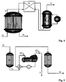
- FIG. 3 shows the structure of a reactor according to the present invention.
- FIG. 4 shows the structure of a reactor system in which the process of the present invention can be carried out.
- FIG. 5 shows a block diagram of a plant in which the process of the present invention can be carried out.
- the present invention accordingly provides a process for preparing isobutene by dissociation of tert-butanol into isobutene and water over a strong acid ion-exchange resin arranged as a fixed bed in at least one reactor.
- the reaction proceeds preferably at a temperature of from 80 to 150° C. and a pressure of from 5 to 25 bar.
- the reaction mixture is separated into isobutene, by-products, water and at least one mixture of undissociated tertiary butanol and water.
- the reactor is operated pseudo-isothermally, i.e.
- the difference in the temperatures of the inflowing and outflowing streams is less than 15 K, preferably less than 10 K and particularly preferably less than 5 K and very particularly preferably less than 1 K.
- the feed to the reactor comprises fresh feed stream and one or more recycle streams which comprise a mixture of undissociated tert-butanol and water.
- the mass ratio of fresh feed stream to the sum of the recycle streams is less than 1:10, preferably less than 1:5 and very particularly preferably less than 1:3.
- the mass ratio of fresh feed stream to the turn of the recycle stream includes all values and subvalues therebetween, especially including 1:1, 1:2, 1:3, 1:4, 1:5, 1:6, 1:7, 1:8 and 1:9.
- the reaction temperature includes all values and subvalues therebetween, especially including 90, 100, 110, 120, 130 and 140° C.
- the reaction pressure includes all values and subvalues therebetween, especially including 6, 8, 10, 12, 14, 16, 18, 20, 22 and 24 bar.
- the difference in temperatures of inflowing and outflowing streams includes all values and subvalues therebetween, especially including 0, 0.5, 1, 2, 3, 4, 5, 6, 7, 8, 9, 10, 11, 12, 13 and 14K.
- the present invention likewise provides isobutene prepared by the process of the invention.
- the present invention further provides a reactor system for carrying out equilibrium reactions isothermally in the liquid phase over fixed-bed catalysts, where at least one of the reaction products is partly, preferably predominantly, present in gaseous form under temperature and pressure conditions under which all starting materials and at least one reaction product are predominantly present in liquid form.
- the present invention provides a reactor system for carrying out the process of the invention, wherein the reactor system has at least two physically separate reaction zones which each have a catalyst arranged in a fixed bed and facilities for maintaining isothermal operation. Between each two reaction zones there is a separation zone having means for bringing at least part of at least one of the products of the equilibrium reaction into the gas phase by changing the pressure or temperature, separating it off from the reaction mixture and discharging it from the reactor.
- the separation zone has means for transferring the remaining reaction mixture to the following reaction zone.
- the temperature or pressure in the subsequent reaction zone can be set to precisely the value in the preceding reaction zone, present if desired.
- This reactor or this reactor system can be utilized, in particular, for carrying out endothermic reactions, for example the dissociation of tertiary ethers to form the corresponding isoolefins and alcohols.
- the process of the present invention makes it possible to carry out the dissociation of tert-butanol with significantly smaller mass flows, in particular smaller amounts of circulated material, while maintaining the same high selectivity. In this way, the energy consumption and the dimensions of the apparatuses can be reduced compared to conventional processes.
- reactors which are connected in series or in parallel, with preference being given to all reactors being operated isothermally. It is possible to use various types of reactor in which ion-exchange resin can be present as a fixed bed, for example fixed-bed reactors, shell-and-tube reactors or reactors of other types.
- the reactors are equipped to allow for isothermal operation, i.e. for the removal or introduction of heat, by using for example heat exchangers.
- the reactor(s) is/are operated pseudo-isothermally, i.e. the difference in the temperatures of the inflowing and outflowing streams (feed stream and product stream) is less than 15 K, preferably less than 10 K, preferably in a single path and the flow through them can be from the top downward or vice versa.
- the reaction temperature in the dissociation reactor(s) is preferably in the range from 80° C. to 150° C., more preferably in the range from 100° C. to 130° C., in the process of the present invention. When a plurality of reactors are used, the temperatures can be identical or different.
- the reaction pressure in the dissociation reactor or reactors is from 5 to 25 bar, with the pressure being selected so as to be sufficiently high for the isobutene formed in the reactors or in the reaction zones of the reactors to remain virtually completely and essentially homogeneously dissolved in the reaction mixture without formation of a gas phase.
- the pressure in the dissociation reactor it is advantageous for the pressure in the dissociation reactor to be greater than the column pressure at the feed points of a column installed downstream of the reactor or the last reactor of a reactor cascade to separate the isobutene obtained from the product stream, because the expansion vaporization can then be utilized to aid the removal of isobutene and a pump can be dispensed with.
- the process is preferably carried out in one or more reactors in which a particulate acidic ion exchanger is present as catalyst in a fixed bed.
- a preferred group of acid ion-exchange resins used as catalysts comprises solid ion-exchange resins bearing sulfonic acid groups.
- suitable ion-exchange resins are those which are prepared by sulfonation of phenol-aldehyde condensates or of cooligomers of aromatic vinyl compounds.
- aromatic vinyl compounds for preparing the cooligomers are: styrene, vinyltoluene, vinylnaphthalene, vinylethylbenzene, methylstyrene, vinylchlorobenzene, vinylxylene and divinylbenzene.
- the resins can be produced as gels, in macroporous form or in sponge form.
- Strongly acidic resins of the styrene-divinylbenzene type are sold, inter alia, under the following trade names: Duolite C20, Duolite C26, Amberlyst 15, Amberlyst 35, Amberlite IR-120, Amberlite 200, Dowex 50, Lewatit SPC 118, Lewatit SPC 108, Lewatit K2611, Lewatit K2631, OC 1501, Lewatit K2671, Lewatit K2629, Lewatit K2431.
- macroporous cation exchangers which have been modified by partial ion exchange or by thermal desulfonation can also be used if desired.
- the ion-exchange resins are preferably used in their H form.
- the ion-exchange capacity is preferably from 2 to 7 eq/kg, in particular from 3 to 6 eq/kg (based on moist commercial resin).
- the ion-exchange capacity includes all values and subvalues therebetween, especially including 2.5, 3, 3.5, 4, 4.5, 5, 5.5, 6 and 6.5 eq/kg.
- macroporous resins for example Lewatit SCP 118, Lewatit SCP 108, Lewatit K2631, Amberlyst 15 or Amberlyst 35.
- the ion-exchange resins can be used as shaped bodies such as cylinders, rings or spheres if desired.
- the particle size of industrial resins is generally in the range from 0.5 to 2 mm.
- the particle size of the industrial resins includes all values and subvalues therebetween, especially including 0.6, 0.8, 1, 1.2, 1.4, 1.6 and 1.8 mm.
- the particle size distribution chosen can also be narrower or broader.
- ion-exchange resins having a very uniform particle size can also be used.
- these can be charged with resins of identical or different particle size (or particle size distribution) or with different or identical shaped bodies.
- the ion-exchange resin can be pretreated, for example by rinsing with water, the TBA or TBA/water mixtures.
- Rinsing is preferably carried out at a temperature of from 40 to 120° C.
- the rinsing temperature includes all values and subvalues therebetween, especially including 50, 60, 70, 80, 90, 100 and 110° C.
- the process is therefore particularly preferably carried out with the dissociation being carried out (virtually) to the equilibrium of the dissociation reaction in a first reaction zone, isobutene being separated off in gaseous form in a subsequent separation zone and the dissociation being continued (virtually) to the equilibrium of the dissociation reaction in a subsequent reaction zone.
- the dissociation reaction proceeds not only to a one-off establishment of equilibrium but instead the reaction can be carried out a number of times, depending on the number of separation zones, to establishment of the reaction equilibrium. In this way, more complete dissociation is achieved in a single pass of the reaction mixture through the reactor or the reactor system than is achieved in conventional reactors or reactor systems.
- the above mentioned mode of operation can be achieved in various ways.
- the pressure and the temperature in the reaction zones of the reactor are preferably chosen so that the reaction mixture is present in the liquid phase.
- the pressure and the temperature in the separation zones are preferably chosen so that at least part of the isobutene is present in the gas phase.
- FIG. 3 shows the structure of such a particular reactor.
- the reactor feed ( 28 ) is fed from below into the reactor and passed into the first reaction region ( 29 ).
- catalyst is located in heatable tubes or other heatable intermediate spaces.
- the reaction which occurs forms isobutene and water to a maximum extent limited by chemical equilibrium being reached.
- part of the isobutene vaporizes and forms a vapor phase ( 30 ), which can, as product stream ( 31 ), be passed directly to column ( 4 ) of FIG. 1 or 2 .
- the vaporization of the isobutene can be additionally reinforced by an optional heating matrix ( 32 ).
- the liquid phase ( 33 ) can be brought back to the permissible reaction temperature by a further heat-exchange element ( 34 ) before it is passed into the second reaction region ( 35 ) which is, like the first reaction region ( 29 ), charged with catalyst and can be heated. There, the reaction continues to a maximum extent limited by the chemical equilibrium.
- the reaction regions ( 29 ) and ( 35 ) are physically separate from one another as a result of the reactor construction.
- the substreams ( 36 ) and ( 31 ) leaving the reactor correspond in total to the stream ( 3 ) in FIGS. 1 and 2 . While stream ( 31 ) is fed directly into the column ( 4 ), stream ( 36 ) can, as shown in FIGS. 1 and 2 , firstly be depleted in water by a separation unit ( 21 ) and then be introduced into column ( 4 ) or can also be fed directly into the column.
- FIG. 4 A different construction of such a reactor is shown in FIG. 4 .
- the reactor feed ( 28 ) is fed into the reactor once again from the bottom in a manner analogous to FIG. 3 or alternatively from the top and passed into the first reaction region ( 29 ).
- catalyst is located in heatable tubes or other heatable intermediate spaces.
- the reaction which occurs forms isobutene and water to a maximum extent limited by chemical equilibrium being reached.
- the operating pressure of the reaction is chosen so as to be sufficiently high for no vaporization to occur in the reactor.
- the reactor output ( 37 ) is fed into a vessel with vaporizer or directly into a vaporizer and forms, as a result of the introduction of heat by the heating element or vaporizer ( 38 ), a vapor phase ( 30 ) which can be passed, as product stream ( 31 ), directly into a column for work-up, e.g. into column ( 4 ) of FIG. 1 or 2 .
- the liquid phase ( 33 ) can be brought back to the permissible reaction temperature by a heat-exchange element ( 39 ) and thus preheat the stream ( 37 ) in order to save energy before it is passed to the second reaction region ( 35 ) which, like the first reaction region ( 29 ) is charged with catalyst and can be heated.
- reaction regions ( 29 ) and ( 35 ) are physically separate from one another as a result of the reactor construction. This type of construction is simple to achieve in engineering terms.
- the reaction mixture can flow through the two reaction regions of the reactor in cocurrent from the bottom upward or from the top downward.
- the substreams ( 36 ) and ( 31 ) leaving the reactor correspond in total to the stream ( 3 ) in FIGS. 1 and 2 . While stream ( 31 ) is fed directly into the column ( 4 ), stream ( 36 ) can, as shown in FIGS. 1 and 2 , firstly be depleted in water by a separation unit ( 21 ) and then be introduced into column ( 4 ) or can also be fed directly into the column.
- this mode of operation can also be achieved by the process being carried out in at least two reactors and the liquid reactor output from the first reactor being transferred to a zone in which part of the reactor output is brought into a gas phase by changing the pressure and/or temperature and thus being separated off from the liquid phase and the liquid phase being passed to the second reactor.
- This intermediate vaporization in the two-stage or multistage reactor system can be carried out by, for example, reducing the pressure to below the reaction pressure. It can be advantageous, in the case of vaporization in a two-stage or multistage reactor system, for heat exchange between the liquid stream fed to vaporization and the liquid stream returned from vaporization to be carried out. Heat losses can be avoided in this way.
- FIG. 5 An appropriate system is shown in FIG. 5 .
- the reactor feed ( 28 ) is fed into the first reaction region ( 29 ) in a manner analogous to FIG. 4 .
- This reaction region comprises one or more reactors in which the catalyst is located in heatable tubes or other heatable intermediate spaces.
- the flow through the reactor(s) can be from the top downward or vice versa.
- the reaction which occurs forms isobutene and water to a maximum extent limited by chemical equilibrium being reached.
- the operating pressure of the reactor is chosen so as to be sufficiently high for no vaporization to occur in the reactor.
- the reactor output ( 37 ) is fed into a vessel with vaporizer or directly into a vaporizer, preferably a kettle vaporizer, and forms, as a result of the introduction of heat by the heating element or vaporizer ( 38 ), a vapor phase ( 30 ) which can be passed, as product stream ( 31 ), directly into a column for work-up, e.g. into column ( 4 ) of FIG. 1 or 2 .
- PC in FIG. 5 refers to a pressure control which can be used to decrease the operating pressure of vaporizer ( 38 ). Vaporization can also be aided by reducing the operating pressure of the vaporizer. In this way, the product is less strongly superheated than in the above-described construction types.
- the liquid phase ( 33 ) can be brought back to the permissible reaction temperature by a heat-exchange element ( 39 ) and thus preheat the stream ( 37 ) in order to save energy before it is passed to the second reaction region ( 35 ) which, like the first reaction region ( 29 ) configured as a single reactor or a plurality of reactors and is charged with catalyst and can be heated. There, the reaction continues to a maximum extent limited by the chemical equilibrium.
- the substreams ( 36 ) and ( 31 ) leaving the reactor correspond in total to the stream ( 3 ) in FIGS. 1 and 2 . While stream ( 31 ) is fed directly into the column ( 4 ), stream ( 36 ) can, as shown in FIGS. 1 and 2 , firstly be depleted in water by a separation unit ( 21 ) and then be introduced into column ( 4 ) or can also be fed directly into the column.
- the mass fraction of vapor includes all values and subvalues therebetween, especially including 10, 15, 20, 25, 30, 35, 40, 45, 50, 55, 60, 65 and 70% by mass, of the feed stream ( 28 ).
- the process of the present invention allows tert-butanol (TBA) to be dissociated into isobutene and water.
- TBA tert-butanol
- the TBA used can be obtained by reaction of isobutene or isobutene-containing hydrocarbon mixtures, in particular raffinate I or selectively hydrogenated cracked C 4 , with water or come from other industrial processes in which TBA has not necessarily been produced by an addition reaction but is obtained as by-product or coproduct, for example in the synthesis of tert-butyl hydroperoxide or in epoxidations using tert-butyl hydroperoxide.
- the TBA content of the feed to the first dissociation reactor which comprises fresh starting material and a TBA/water recycle stream, is preferably from 40 to 99% by mass, more preferably from 55 to 98% by mass.
- the TBA content of the feed of the first dissociation reactor includes all values and subvalues therebetween, especially including 45, 50, 55, 60, 65, 70, 75, 80, 85, 90 and 95% by mass.
- the space velocity which is particularly advantageous in an individual case depends on the water content of the reaction mixture and to a large degree on the reaction temperature and the activity of the catalyst used and has to be determined individually for each catalyst.
- the space velocity (LHSV) in liters of feed per liter of catalyst after swelling per hour is generally from 10 to 100 l/(l*h) at a reaction temperature of from 80 to 100° C., from 15 to 300 l/(l*h) at a reaction temperature of from 100 to 130° C. and up to 600 l/(l*h) at a reaction temperature of from 130 to 150° C.
- lower space velocities can also be chosen.
- the space velocity at 80 to 100° C. includes all values and subvalues therebetween, especially including 20, 30, 40, 50, 60, 70, 80 and 90 l/(l*h).
- the space velocity of 130 to 150° C. includes all values and subvalues therebetween, especially including 50, 100, 150, 200, 250, 300, 350, 400, 450, 500 and 550 l/(l*h).
- the reactor output from the dissociation according to the present invention of TBA is preferably separated into isobutene, by-product, water and a TBA/water mixture which is recirculated to the reactor and has a water content of less than 20% by mass, preferably less than 18% by mass, and more preferably less than 10% by mass and particularly preferably from 3 to 9% by mass.
- the water content of the TBA/water mixture includes all values and subvalues between 0 and 20% by mass, especially including 1, 2, 3, 4, 5, 6, 8, 10, 12, 14, 16 and 18% by mass.
- the output from the reactor is preferably worked up by separating off the major part of the isobutene from the reactor output as an isobutene/water azeotrope at the top of a first column. After separating off part of the water from the overhead product from the first column, e.g. by phase separation, virtually water-free isobutene can be obtained from it by azeotropic distillation in a second column, for example (16).
- An isobutene-containing mixture comprising isobutene and water in the above mentioned concentrations is likewise subject matter of the present invention.
- the purity of the isobutene includes all values and subvalues therebetween, especially including 97.5, 98, 98.5, 99, 99.5, 99.6, 99.7, 99.8 and 99.9% by mass.
- the maximum water content of the isobutene includes all values and subvalues therebetween, especially including 10, 20, 30, 40, 50, 100, 150, 200, 250, 500, 750, 1000, 2000, 3000, 4000, 5000, 6000, 7000, 8000 and 9000 ppm.
- C 8 -hydrocarbons and longer-chain hydrocarbons which are present as by-products in the output from the reactor can be separated off from the isobutene-free bottom product from the first column ( 4 ), for example as overhead product in a third column ( 6 ).
- the bottom product from the first column ( 4 ) or the third column ( 6 ) can be separated in a fifth column ( 9 ) into a mixture of water and TBA, which may contain isobutene, as overhead product and, as bottom product, water which may contain organic impurities, with the tert-butanol/water mixture being at least partly recirculated to the reactor for dissociation of tert-butanol.
- 2-Butanol which may be present as impurity in the bottom product from the first or third column can, for example, be separated off from the water separated off as bottom product by distillation in a further column or as side stream in the fifth, for example column ( 9 ).
- the distillate ( 12 ) from the isobutene enrichment ( 4 a ) in column ( 4 ), which consists essentially of an isobutene/water azeotrope, can be worked up in various ways. In particular it can be condensed and transferred to a settling or separation vessel or alternatively be condensed directly in a settling or separation vessel having heat-exchange elements and subjected to a liquid/liquid separation. After the liquid/liquid separation, part of the organic liquid can be fed to a further column ( 16 ) at the top or in the upper part of the column to give virtually water-free isobutene ( 18 ) at the bottom and an isobutene/water azeotrope at the top of this column. This isobutene/water azeotrope can be returned to the liquid/liquid separation vessel.
- the reactor output before separation into various fractions in a first column or a fraction obtained from it after separation can be subjected to removal of part of the water present in the reactor output or in the fractions obtained, e.g. by pervaporation and/or vapor permeation by means of a membrane.
- the separation of part of the water from the reactor output prior to separation into various fractions in a first column can also be achieved by phase separation in a separation or settling vessel.
- the removal of the water with the aid of a membrane can be carried out by reverse osmosis (retentate and permeate are liquid), by pervaporation (liquid retentate, gaseous permeate) or by vapor permeation (retentate and permeate are gaseous). Separation by simultaneous pervaporation and vapor permeation is also possible.
- the removal of the water by means of a membrane according to the present invention is preferably carried out by pervaporation (liquid retentate, gaseous permeate).
- hydrophilic membranes can be polymer membranes or inorganic membranes.
- polymer membranes from the companies Sulzer Chemtech, CM-Celfa, GKSS or Sophisticated Systems (polyimide membrane).
- Types which can be used are, for example, Pervap 2200, Pervap 2201, Pervap 2202 or Pervap 2510 from Sulzer or the type 2S-DP-H018 from Sophisticated Systems.
- inorganic membranes mention may be made, for example, of the following: SMS (Sulzer Chemtech); Silica (Pervatech); NaA (Mitsui or Smart Chemical). It is also possible to use combinations of an inorganic membrane or inorganic support material and a polymer membrane or applied separation layer of polymer.
- the removal of water over the inorganic membranes is preferably carried out at a temperature of from 20 to 200° C., and that over polymer membranes is preferably carried out at a temperature of from 20 to 150° C.
- the removal of water is particularly preferably carried out at a temperature of from 60 to 140° C. over both types of membrane.
- the process of the present invention is preferably carried out at a pressure of the mixture (liquid, gaseous or mixed phase) fed to the membrane unit of from 0.5 to 30 bar, preferably from 0.8 to 20 bar.
- the pressure on the permeate side of the membrane is preferably from 0.001 to 1 bar.
- the pressure of the mixture fed to the membrane unit includes all values and subvalues therebetween, especially including 1, 2, 3, 4, 5, 10, 15, 20 and 25 bar.
- the pressure on the permeate side includes all values and subvalues therebetween especially including 0.005, 0.01, 0.05, 0.1, 0.5, 0.6, 0.7, 0.8 and 0.9 bar.
- the differential pressure is preferably from 0.01 to 20 bar, and in the case of inorganic membranes it is preferably from 0.01 to 30 bar.
- the differential pressures are particularly preferably in the range from 1 to 5 bar.
- the differential pressure for polymer membranes includes all values and subvalues therebetween, especially including 0.05, 0.1, 0.5, 1, 2, 4, 6, 8, 10, 12, 14, 16 and 18 bar.
- the differential pressure for inorganic membranes includes all values and subvalues therebetween especially including 0.05, 0.1, 0.5, 1, 2, 4, 6, 8, 10, 12, 14, 16, 18, 20, 22, 24, 26 and 28 bar.
- the mass flow (kg of permeate per square meter of membrane surface per hour) is preferably from 0.1 to 10 kg/(m 2 h), particularly preferably from 1 to 8 kg/(m 2 h).
- the mass flow includes all values and subvalues therebetween, especially including 0.5, 1, 1.5, 2, 2.5, 3, 3.5, 4, 4.5, 5, 5.5, 6, 6.5, 7, 7.5, 8, 8.5, 9 and 9.5 kg/(m 2 h).
- the water separated off as permeate preferably has a content of organic constituents, in particular TBA, of less than 10% by mass, preferably less than 5% by mass and very particularly preferably from 3 to 0.05% by mass.
- the content of organic constituents includes all values and subvalues therebetween, especially including 0.005, 0.01, 0.05, 0.1, 0.5, 1, 2, 3, 4, 5, 6, 7, 8 and 9% by mass. Smaller values down to 0.001% by mass can also be achieved, but this is usually not necessary and also not economically viable.
- Suitable streams are, for example, the reaction mixture leaving the dissociation reactor or the recirculated TBA/water mixture from the azeotrope column (for example, column ( 9 )).
- the reaction mixture leaving the dissociation reactor is, apart from the wastewater streams, the stream having the highest water content. A relatively large part of the water can therefore be separated off from it by a membrane process with the least energy input compared to other streams. Further possibilities may be found in the reactor feed.
- part of the water present can be removed from, for example, one of the streams ( 1 ), ( 10 ) and/or the mixed stream by pervaporation and/or vapor permeation by means of a membrane. This makes it possible to achieve TBA contents of greater than 90% by mass, which allow a particularly high conversion in the reactor (system).
- the overhead product ( 10 ) from the azeotrope column ( 9 ), which is recirculated to the reactor ( 2 ), has an approximately azeotropic composition, i.e. a water content of from about 20 to 12% by mass.
- the water content includes all values and subvalues therebetween, especially including 1, 2, 4, 6, 8, 10, 12, 14, 16 and 18% by mass.
- Use of a membrane process enables the water content of this to be reduced to values of less than 12% by mass, in particular from 1 to 10% by mass, so that particularly little water is introduced into the reactor, as a result of which the space-time yield in the dissociation reactor increases.
- the membrane process for example, ( 21 ) can be utilized to dewater the water-containing stream, for example, ( 26 ) which is obtained as bottoms from the first separation column, for example, ( 4 ) and is partly recirculated to the reactor.
- FIG. 1 A block diagram of a plant in which the process of the present invention can be carried out is shown in FIG. 1 .
- the feed (mixture) ( 1 ) together with the TBA/water azeotrope or approximately azeotropic composition ( 10 ) is fed into the reactor ( 2 ).
- the reactor ( 2 ) can consist of a single reactor or a reactor system (see below).
- the reaction mixture ( 3 ) leaving the reactor ( 2 ) is fed into the column ( 4 ) consisting of ( 4 a ) and ( 4 b ).
- ( 4 a ) represents an isobutene enrichment part
- ( 4 b ) represents a drift part, as upper and lower part of the column, respectively.
- the reaction mixture ( 3 ) leaving the reactor ( 2 ) can be dewatered and thus largely freed of water of reaction before it is introduced into the column ( 4 ).
- the dewatering module ( 21 ) used can be a decanter (separation or settling vessel) which separates any two-phase mixture formed into an organic liquid stream ( 3 A) and an aqueous liquid stream ( 3 B). Significantly more water can be separated off by a membrane process, which likewise produces an organic liquid stream ( 3 A) and an aqueous liquid stream ( 3 B).
- the organic liquid stream ( 3 A) is introduced into the column ( 4 ) and the aqueous liquid stream ( 3 B) is fed into column ( 9 ) for discharge and further purification of the water or is passed to direct disposal.
- the water phase ( 19 ) can be fed into the column ( 9 ).
- Part of the isobutene phase is recirculated as recycle stream ( 14 ) to the top of the column ( 4 ), and the other part ( 15 ) is separated in a column ( 16 ) into pure isobutene ( 18 ) and a water/isobutene azeotrope ( 17 ) which is returned to the separation vessel ( 13 ).
- a fresh water stream ( 20 ) can optionally be added at the top or in the enrichment section ( 4 a ) of the column ( 4 ).
- the bottom product ( 5 ) of the column ( 4 ) is passed to column ( 6 ) where C 8 -hdyrocarbons are taken off as overhead product ( 7 ).
- the bottom product ( 8 ) is separated in column ( 9 ) into water which possibly contains organic components (e.g. 2-butanol and/or C 12 -hydrocarbons) ( 11 ) and a TBA/water azeotrope ( 10 ) which may contain small amounts of isobutene (from stream ( 19 )).
- Stream ( 10 ) is recirculated to the reactor ( 2 ). Any organic components (e.g. 2-butanol (SBA) and/or C 12 -hydrocarbons) present in the wastewater stream ( 11 ) can easily be separated off from pure water by distillation.
- organic components e.g. 2-butanol (SBA) and/or C 12 -hydrocarbons
- 2-butanol can be discharged in a targeted fashion by taking off a stream from the vapor phase of the vaporizer of the column or a gaseous or liquid stream from the stripping section of the column ( 9 ) as side stream ( 11 A).
- FIG. 2 A block diagram of an alternative plant in which the process of the present invention can be carried out is shown in FIG. 2 .
- the feed (mixture) ( 1 ) together with the TBA/water azeotrope or approximately azeotropic composition ( 10 ) is fed into the reactor ( 2 ).
- the reactor ( 2 ) can consist of a single reactor or a reactor system (see below).
- the reaction mixture ( 3 ) leaving the reactor ( 2 ) is fed into the column ( 4 ) consisting of isobutene enrichment part ( 4 a ) and drift part ( 4 b ). If desired, the reaction mixture ( 3 ) leaving the reactor ( 2 ) can be dewatered and thus largely freed of water of reaction before it is introduced into the column ( 4 ).
- the dewatering module ( 21 ) used can be a decanter (separation or settling vessel) which separates any two-phase mixture formed into an organic liquid stream ( 3 A) and an aqueous liquid stream ( 3 B).
- a decanter separation or settling vessel
- the organic liquid stream ( 3 A) is introduced into the column ( 4 ) and the aqueous liquid stream ( 3 B) is fed into column ( 9 ) for discharge and further purification of the water or is passed to direct disposal.
- isobutene containing small amounts of water is separated off and is separated in the settling vessel ( 13 ) into an isobutene phase and a water phase.
- the water phase ( 19 ) can be fed into the column ( 9 ).
- Part of the isobutene phase is recirculated as recycle stream ( 14 ) to the top of the column ( 4 ), and the other part ( 15 ) is separated in a column ( 16 ) into pure isobutene ( 18 ) and a water/isobutene azeotrope ( 17 ) which is returned to the separation vessel ( 13 ).
- a fresh water stream ( 20 ) can optionally be added at the top or in the enrichment section of the column ( 4 ).
- the bottom product ( 5 ) is separated in column ( 9 ) into water which possibly contains organic components (e.g. 2-butanol and/or C 12 -hydrocarbons) ( 11 ) and a TBA/water azeotrope ( 10 ) which may contain small amounts of isobutene (from stream ( 19 )).
- Stream ( 10 ) is recirculated to the reactor ( 2 ). All or part of the vapor ( 27 ) from the column ( 9 ) can be introduced into column ( 4 ) in order to save energy and adjust the concentration.
- a part ( 26 ) of the bottom stream ( 5 ) can be fed directly to the reactor.
- Any organic components (e.g. 2-butanol and/or C 12 -hydrocarbons) present in the wastewater stream ( 11 ) can easily be separated off from pure water by distillation.
- a gaseous or liquid side stream ( 22 ) is taken from the column ( 4 ) and passed to column ( 23 ) where the C 8 -hydrocarbons together with TBA and water are taken off as bottom product ( 24 ). Isobutene and TBA are recovered as overhead product ( 25 ) and are returned to the column ( 4 ).
- a further possible option is firstly to introduce the feed stream ( 1 ) into one or more further reactor(s) and to feed the prereacted mixture into column ( 4 a ).
- the fractional distillation of streams obtained in the process of the present invention can be carried out in one or more columns containing internals which may comprise trays, rotating internals, random and/or ordered beds or packing.
- the separation of the isobutene from the reactor output by distillation is preferably carried out in a single column.
- the runback is either sprayed by means of rotating funnels or spread as a film over a heated wall by means of rotor.
- Irregular beds of various packing elements can also be employed in columns used in the process of the present invention.
- the packing elements can consist of virtually any materials, e.g. steel, stainless steel, copper, carbon, stoneware, porcelain, glass, plastics, etc., or mixtures thereof, and have various shapes, e.g. spheres, rings with smooth or profiled surfaces, rings with internal struts or holes through the wall, wire mesh rings, saddles or spirals.
- Packing having a regular geometry can, for example, consist of metal or plastic sheets or mesh.
- types of packing are Sulzer mesh packing BX, Sulzer lamellar packing Mellapak made of sheet metal, high-performance packing such as MellapakPlus, structured packing from Sulzer (Optiflow), Montz (BSH) and Kuhni (Rombopak).
- the operating pressure in the columns used in the process of the present invention is preferably in the range from 0.5 to 15 bar abs (bara), particularly preferably from 1 to 10 bara.
- the operating pressure includes all values and subvalues therebetween, especially including 1, 2, 3, 4, 5, 6, 7, 8, 9, 10, 11, 12, 13, and 14 bara.
- the column ( 4 ) used for separation of the reactor output preferably has from 5 to 80 theoretical plates, more preferably from 10 to 60 theoretical plates.
- the number of theoretical plates includes all values and subvalues therebetween, especially including 10, 15, 20, 25, 30, 35, 40, 45, 50, 55, 60, 65, 70 and 75.
- the feed plate depends on the composition of the feed. It has been found to be advantageous for the reactor output to be fed in on the 4th to 55th theoretical plate counted from the top, in particular the 5th to 50th theoretical plate, in the lower section of the column, in particular the isobutene enrichment part ( 4 a ) of FIG. 1 and FIG. 2 .
- the fresh water ( 21 ) is fed in at the top of the column ( 4 ) on plate 1 . This likewise applies to the runback ( 14 ).
- the optional vapor stream ( 27 ) from the column ( 9 ) is fed in at the bottom of the column ( 4 ).
- the gaseous or liquid stream ( 22 ) it has been found to be advantageous for the gaseous or liquid stream ( 22 ) to be taken off at the 4th to 65th theoretical plate counted from the top, in particular the 5th to 60th theoretical plate, of the column ( 4 ) of FIG. 2 .
- the isobutene-rich stream ( 25 ) is fed back in at the same point or preferably a higher point (higher up in the column: isobutene enrichment part ( 4 a ), i.e. on the 2nd to 65th theoretical plate counted from the top, in particular the 3rd to 60th theoretical plate, of the column ( 4 ) of FIG. 2 .
- the column ( 9 ) used for discharging the wastewater and concentrating the TBA preferably has from 5 to 70 theoretical plates, more preferably from 8 to 65 theoretical plates.
- the number of theoretical plates includes all values and subvalues therebetween, especially including 10, 15, 20, 25, 30, 35, 40, 45, 50, 55, 60, and 65.
- the feed plate depends on the composition of the feed. It has been found to be advantageous for the stream ( 5 ) in FIG. 2 or the stream ( 8 ) in FIG. 1 to be fed in on the 1st to 55th theoretical plate counted from the top, in particular the 1st to 45th theoretical plate.
- the possible wastewater ( 3 B) and ( 19 ) is fed in on the 1st to 60th theoretical plate counted from the top, in particular the 1st to 50th theoretical plate.
- the column ( 16 ) used for drying the isobutene preferably has from 4 to 35 theoretical plates, more preferably from 5 to 30 theoretical plates.
- the number of theoretical plates includes all values and subvalues therebetween, especially including 10, 15, 20 and 25. It has been found to be advantageous for the feed ( 15 ) to be fed in on the 1st to 6th theoretical plate counted from the top, in particular on the 1 st to 4th theoretical plate.
- the column ( 6 ) used in FIG. 1 for discharging C 8 -hydrocarbons preferably has from 4 to 75 theoretical plates, more preferably from 5 to 50 theoretical plates.
- the number of theoretical plates includes all values and subvalues therebetween, especially including 10, 15, 20, 25, 30, 35, 40, and 45.
- the feed plate depends on the composition of the feed. It has been found to be advantageous for the stream ( 5 ) in FIG. 1 to be fed in on the 1st to 55th theoretical plate counted from the top, in particular the 1 st to 45th theoretical plate.
- the column ( 23 ) used in FIG. 2 for discharging C 8 -hydrocarbons preferably has from 4 to 65 theoretical plates, more preferably from 5 to 50 theoretical plates.
- the number of theoretical plates includes all values and subvalues therebetween, especially including 10, 15, 20, 25, 30, 35, 40, and 45. It has been found to be advantageous for the feed ( 22 ) to be fed in on the 1st to 25th theoretical plate counted from the top, in particular on the 1st to 15th theoretical plate.
- the product stream ( 25 ) is taken off as distillate at the top of the column, either in gaseous or liquid form, preferably in gaseous form.
- Customary components such as pumps, compressors, valves, heat exchangers and vaporizers are not found in the block diagrams, but these are self-evident components of a plant.
- a particular feature of the reactor system for carrying out equilibrium reactions isothermally in the liquid phase over fixed-bed catalysts, where at least one of the reaction products is partly, preferably predominantly, present in gaseous form under temperature and pressure conditions under which all starting materials and at least one reaction product are predominantly present in liquid form, in particular for carrying out the process of the present invention is that the reactor system has at least two physically separate reaction zones which each have a catalyst arranged in a fixed bed and facilities for maintaining isothermal operation, where between each two reaction zones there is a separation zone having means for bringing at least part of at least one of the products of the equilibrium reaction into the gas phase by changing the pressure or temperature, separating it off from the reaction mixture and discharging it from the reactor and for transferring the remaining reaction mixture to the following reaction zone, with a further means which enables the temperature or pressure in the subsequent reaction zone to be set to precisely the value in the preceding reaction zone being able to be present if desired.
- the means of setting the temperature can be, for example, customary plates or tube heat exchangers.
- the means of bringing at least one of the products of the equilibrium reaction into the gas phase can likewise be a heat exchanger, so that this reaction product is vaporized by introduction of thermal energy into the reaction mixture.
- the means can be a kettle vaporizer or a heated vessel which enables the pressure to be decreased when the reaction mixture enters the separation zone. In such a reactor design, the pressure of the reaction mixture as it enters the reaction zone following the separation zone is lower than in the preceding reaction zone.
- the preparation of isobutene is carried out in a plant of the type shown in FIG. 1 and FIG. 5 , with the particular feature that no removal of water using the module ( 21 ) is carried out and the streams 3 and 3 A therefore has the same composition.
- the fresh water stream ( 20 ) and the wastewater stream ( 3 B) are dispensed with.
- the wastewater stream ( 19 ) is disposed of directly.
- the reaction section ( 2 ) is in two stages as shown in FIG. 5 .
- the reactor ( 29 ) is a laboratory tube reactor operated isothermally at 120° C. and having a catalyst volume of about 310 ml. Amberlyst 15 is used as catalyst.
- the second reactor ( 35 ) is likewise a laboratory tube reactor operated isothermally at 120° C. and having a catalyst volume of about 310 ml. Amberlyst 15 is likewise used as catalyst.
- a heatable vessel is used for intermediate vaporization.
- the diameter of the columns ( 4 ), ( 6 ), ( 9 ) and ( 16 ) is in each case 50 mm. Random metal packing elements are used. About 30 theoretical plates are installed in column ( 4 ), and the reactor output ( 3 ) is fed in on the 20th theoretical plate counted from the top. The runback ( 14 ) is introduced at the top of the column on plate 1 . About 18 theoretical plates are installed in column ( 6 ), and the feed ( 5 ) from column ( 4 ) is fed in on the 12th theoretical plate counted from the top. About 13 theoretical plates are installed in column ( 9 ), and the feed ( 8 ) from column ( 6 ) is fed in on the 2nd theoretical plate counted from the top. The side stream ( 11 A) is taken off in vapor form at approximately the 10th theoretical plate, counted from the top.
- the feed ( 1 ) used for the experiments is taken from an industrial plant for the preparation of isobutene and had the composition shown in Table 1.
- Some C 8 -hydrocarbons and other high boilers are already present in small amounts in the feed and further amounts of them are formed in the dissociation of the TBA in the reactor system.
- the stream numbers in the following table correspond to those in FIG. 1
- those in the reaction section correspond to those in FIG. 5 .
- Components present in a concentration of less than 0.1 parts by mass in the mixture are generally not reported in the Table.
- the pressure in the reactor ( 29 ) is 19 bar abs.
- the pressure in the reactor ( 35 ) is 18 bar abs.
- the intermediate vaporization ( 38 ) is carried out at 15 bar abs. .
- the columns ( 4 ), ( 6 ), ( 9 ) and ( 16 ) are each operated at a pressure of about 6 bar abs. at the top.
- Column ( 4 ) is equipped with a dephlegmator and operated using a runback stream of about 11.5 kg/h. A space-time yield of 2.7 kg/(l*h) based on the total amount of catalyst used is obtained.
- the preparation of isobutene is carried out in a plant of the type shown in FIG. 1 , with the particular feature that no removal of water by means of the module ( 21 ) is carried out and the streams 3 and 3 A therefore have the same composition.
- the fresh water stream ( 20 ) and the wastewater stream ( 3 B) are dispensed with.
- the wastewater stream ( 19 ) is disposed of directly.
- the reaction section ( 2 ) is configured as a single stage.
- the reactor ( 2 ) is a laboratory tube reactor operated isothermally at 120° C. and having a catalyst volume of about 285 ml. Amberlyst 15 is used as catalyst.
- the diameter of the columns ( 4 ), ( 6 ), ( 9 ) and ( 16 ) is in each case 50 mm. Metal packing elements (Pall rings) are used in each case. About 30 theoretical plates are installed in column ( 4 ), and the reactor output ( 3 ) is fed in on the 20th theoretical plate counted from the top.
- the runback ( 14 ) is introduced at the top of the column on plate 1 .
- the feed ( 1 ) used for the experiments is taken from an industrial plant for the preparation of isobutene and has the composition shown in Table 2. Some C 8 -hydrocarbons and other high boilers are already present in small amounts in the feed and further amounts of them are formed in the dissociation of the TBA in the reactor system.
- the stream numbers in the following table correspond to those in FIG. 1 . Components present in a concentration of less than 0.1 parts by mass in the mixture are generally not reported in the Table.
- the pressure in the reactor ( 2 ) is 19 bar abs. .
- the columns ( 4 ), ( 6 ), ( 9 ) and ( 16 ) are operated at a pressure of about 6 bar abs. at the top.
- Column ( 4 ) is equipped with a dephlegmator and operated using a runback stream of about 5.1 kg/h. A space-time yield of 5.8 kg/(l*h) based on the total amount of catalyst used is obtained.
- DE 3151446 gives examples in which the ratio of the mass flows of fresh feed to circulated streams is reported as from 1:7.4 to 1:16.6 (see Table 1 in that document), while Example 2 achieves a ratio of the mass flows of fresh feed ( 1 ) to recycle stream ( 10 ) of 1:2.9 and Example 1 achieves a ratio of 1:2.16 as a result of the higher partial conversion in the reactor system.
- These values can be improved further by, for example, increasing the degree of concentration to the TBA/water azeotrope in column ( 9 ).
Landscapes
- Chemical & Material Sciences (AREA)
- Organic Chemistry (AREA)
- Chemical Kinetics & Catalysis (AREA)
- Physics & Mathematics (AREA)
- Fluid Mechanics (AREA)
- Engineering & Computer Science (AREA)
- Analytical Chemistry (AREA)
- Oil, Petroleum & Natural Gas (AREA)
- Water Supply & Treatment (AREA)
- Organic Low-Molecular-Weight Compounds And Preparation Thereof (AREA)
- Catalysts (AREA)
- Low-Molecular Organic Synthesis Reactions Using Catalysts (AREA)
Applications Claiming Priority (2)
| Application Number | Priority Date | Filing Date | Title |
|---|---|---|---|
| DE10327215.1 | 2003-06-17 | ||
| DE10327215A DE10327215A1 (de) | 2003-06-17 | 2003-06-17 | Verfahren zur Herstellung von Isobuten aus tert.-Butanol |
Publications (2)
| Publication Number | Publication Date |
|---|---|
| US20050014985A1 US20050014985A1 (en) | 2005-01-20 |
| US7235704B2 true US7235704B2 (en) | 2007-06-26 |
Family
ID=33394844
Family Applications (1)
| Application Number | Title | Priority Date | Filing Date |
|---|---|---|---|
| US10/868,904 Expired - Fee Related US7235704B2 (en) | 2003-06-17 | 2004-06-17 | Process for preparing isobutene from tert-butanol |
Country Status (10)
| Country | Link |
|---|---|
| US (1) | US7235704B2 (zh) |
| EP (1) | EP1489062B1 (zh) |
| JP (1) | JP4800584B2 (zh) |
| KR (1) | KR101104106B1 (zh) |
| CN (1) | CN1331829C (zh) |
| DE (1) | DE10327215A1 (zh) |
| ES (1) | ES2400558T3 (zh) |
| PL (1) | PL1489062T3 (zh) |
| SG (1) | SG153629A1 (zh) |
| TW (1) | TW200503987A (zh) |
Cited By (2)
| Publication number | Priority date | Publication date | Assignee | Title |
|---|---|---|---|---|
| US20120238788A1 (en) * | 2009-07-29 | 2012-09-20 | Wright Michael E | Process for the dehydration of aqueous bio-derived terminal alcohols to terminal alkenes |
| WO2013085964A3 (en) * | 2011-12-05 | 2013-08-01 | Saudi Arabian Oil Company | Hydrophilic membrane integrated olefin hydration process |
Families Citing this family (26)
| Publication number | Priority date | Publication date | Assignee | Title |
|---|---|---|---|---|
| DE10241762A1 (de) * | 2002-09-10 | 2004-03-18 | Oxeno Olefinchemie Gmbh | Verfahren zur Herstellung von wasserfreiem tert.-Butanol |
| EP1431264B1 (de) * | 2002-12-19 | 2010-01-20 | Evonik Oxeno GmbH | Verfahren zur Herstellung von tert.-Butanol |
| DE10260991A1 (de) * | 2002-12-24 | 2004-07-08 | Oxeno Olefinchemie Gmbh | Verfahren zur Herstellung von tert.-Butanol mittels Reaktivrektifikation |
| RU2419595C2 (ru) * | 2005-07-06 | 2011-05-27 | Бп Кемикэлз Лимитед | Реакционная ректификация для дегидратации смешанных спиртов |
| CN101381273B (zh) * | 2007-09-06 | 2012-08-22 | 四川古杉油脂化学有限公司 | 一种用叔丁醇制备异丁烯的方法及装置 |
| EP2070896A1 (en) | 2007-12-12 | 2009-06-17 | BP p.l.c. | A process for the conversion of n-butanol to di-isobutene and propene |
| EP2105428A1 (en) | 2007-12-12 | 2009-09-30 | BP p.l.c. | A process for the conversion of n-butanol to di-isobutene |
| EP2070894A1 (en) | 2007-12-12 | 2009-06-17 | BP p.l.c. | A process for the conversion of n-butanol of n-butanol to di-isobutene and pentene |
| US8067655B2 (en) * | 2008-05-29 | 2011-11-29 | Lyondell Chemical Technology, L.P. | Diisobutylene process |
| CN102020526B (zh) * | 2009-09-09 | 2013-04-24 | 中国石油天然气股份有限公司 | 一种采用叔丁醇制备异丁烯的方法 |
| KR101161845B1 (ko) * | 2010-04-26 | 2012-07-03 | 송원산업 주식회사 | 알켄 화합물의 제조 방법 |
| DE102012105879A1 (de) | 2012-07-02 | 2014-01-02 | Oxea Gmbh | Verfahren zur Herstellung von Isononylderivaten |
| DE102012105876A1 (de) | 2012-07-02 | 2014-01-02 | Oxea Gmbh | Verfahren zur Herstellung von Terephthalsäure und ihren Derivaten |
| DE102012105878A1 (de) | 2012-07-02 | 2014-01-02 | Oxea Gmbh | Verfahren zur Herstellung von Isopentanderivaten |
| DE102012105877A1 (de) | 2012-07-02 | 2014-01-02 | Oxea Gmbh | Verfahren zur Herstellung von Diisobuten |
| DE102012105874A1 (de) | 2012-07-02 | 2014-01-02 | Oxea Gmbh | Verfahren zur Herstellung von Isononansäurevinylestern |
| CN103804116B (zh) * | 2012-11-08 | 2016-03-30 | 中国石油化工股份有限公司 | 一种甲基叔丁基醚裂解制聚合级异丁烯的方法 |
| EP3228384B1 (en) | 2014-12-03 | 2020-07-01 | China Petroleum & Chemical Corporation | Catalyst and preparation method thereof, and method for preparing isobutylene by applying the same |
| KR20170035621A (ko) | 2015-09-23 | 2017-03-31 | 롯데케미칼 주식회사 | 터트-부탄올로부터 이소부틸렌의 제조 방법 |
| KR101880741B1 (ko) | 2016-09-27 | 2018-07-20 | 롯데케미칼 주식회사 | 터트-부탄올로부터 이소부틸렌의 제조 방법 |
| KR101899136B1 (ko) | 2016-09-27 | 2018-09-14 | 롯데케미칼 주식회사 | 터트-부탄올로부터 이소부틸렌의 제조 방법 |
| CN109776247A (zh) * | 2018-03-30 | 2019-05-21 | 住友化学株式会社 | 异丁烯的制造方法及异丁烯的制造装置 |
| CN109550520A (zh) * | 2018-11-06 | 2019-04-02 | 丹东明珠特种树脂有限公司 | 叔丁醇脱水制备高纯度异丁烯用催化剂、其制备方法和其脱水应用 |
| FR3102070B1 (fr) * | 2019-10-17 | 2021-09-24 | Commissariat Energie Atomique | Réacteur échangeur à tubes et calandre permettant l’injection étagée d’un réactif |
| KR102325331B1 (ko) | 2019-12-20 | 2021-11-10 | 한화토탈 주식회사 | 터트-부탄올로부터 이소부틸렌의 제조방법 |
| CN111187137B (zh) * | 2020-02-13 | 2024-02-09 | 浙江信汇新材料股份有限公司 | 一种tba制备聚合级异丁烯的工艺 |
Citations (9)
| Publication number | Priority date | Publication date | Assignee | Title |
|---|---|---|---|---|
| US3665048A (en) | 1970-01-14 | 1972-05-23 | Atlantic Richfield Co | Process to produce high purity isobutylene |
| DE2913796A1 (de) | 1978-04-10 | 1979-10-11 | Nippon Oil Co Ltd | Verfahren zum kontinuierlichen abtrennen und gewinnen von isobuten |
| US4208540A (en) | 1978-12-22 | 1980-06-17 | Nippon Oil Co., Ltd. | Process for separation and recovery of isobutene |
| DE3151446A1 (de) | 1981-12-24 | 1983-07-14 | Chemische Werke Hüls AG, 4370 Marl | Verfahren zur herstellung von hochreinem isobuten durch dehydratisierung von tertiaer-butanol |
| EP0255948A2 (en) | 1986-08-06 | 1988-02-17 | Mitsubishi Rayon Co., Ltd. | Process for producing isobutylene |
| WO1993021139A1 (en) | 1992-04-22 | 1993-10-28 | Bp Chemicals Limited | Process for the production of olefins |
| US5518699A (en) | 1993-07-08 | 1996-05-21 | Huels Aktiengesellschaft | Method of carrying out chemical reactions in reaction distillation columns |
| DE19936675A1 (de) | 1999-08-04 | 2001-07-05 | Borsig Energy Gmbh | Verfahren zum Betreiben eines kontinuierlich arbeitenden Reaktors sowie nach diesem Verfahren arbeitender Reaktor |
| US20040171891A1 (en) | 2002-12-19 | 2004-09-02 | Oxeno Olefinchemie Gmbh | Process for preparing tert-butanol |
Family Cites Families (1)
| Publication number | Priority date | Publication date | Assignee | Title |
|---|---|---|---|---|
| FR2747120B1 (fr) * | 1996-04-09 | 1998-05-15 | Inst Francais Du Petrole | Procede de production d'olefine(s) tertiaire(s) par decomposition de l'ether correspondant a l'aide d'un catalyseur particulier |
-
2003
- 2003-06-17 DE DE10327215A patent/DE10327215A1/de not_active Withdrawn
-
2004
- 2004-03-29 JP JP2004096756A patent/JP4800584B2/ja not_active Expired - Fee Related
- 2004-04-02 SG SG200401997-2A patent/SG153629A1/en unknown
- 2004-04-21 PL PL04101656T patent/PL1489062T3/pl unknown
- 2004-04-21 EP EP04101656A patent/EP1489062B1/de not_active Expired - Lifetime
- 2004-04-21 ES ES04101656T patent/ES2400558T3/es not_active Expired - Lifetime
- 2004-06-10 TW TW093116732A patent/TW200503987A/zh unknown
- 2004-06-16 CN CNB2004100495231A patent/CN1331829C/zh not_active Expired - Fee Related
- 2004-06-17 KR KR1020040045140A patent/KR101104106B1/ko not_active IP Right Cessation
- 2004-06-17 US US10/868,904 patent/US7235704B2/en not_active Expired - Fee Related
Patent Citations (11)
| Publication number | Priority date | Publication date | Assignee | Title |
|---|---|---|---|---|
| US3665048A (en) | 1970-01-14 | 1972-05-23 | Atlantic Richfield Co | Process to produce high purity isobutylene |
| DE2913796A1 (de) | 1978-04-10 | 1979-10-11 | Nippon Oil Co Ltd | Verfahren zum kontinuierlichen abtrennen und gewinnen von isobuten |
| GB2022129A (en) | 1978-04-10 | 1979-12-12 | Nippon Oil Co Ltd | Process for the separation and recovery of isobutene |
| US4208540A (en) | 1978-12-22 | 1980-06-17 | Nippon Oil Co., Ltd. | Process for separation and recovery of isobutene |
| DE3151446A1 (de) | 1981-12-24 | 1983-07-14 | Chemische Werke Hüls AG, 4370 Marl | Verfahren zur herstellung von hochreinem isobuten durch dehydratisierung von tertiaer-butanol |
| US4423271A (en) | 1981-12-24 | 1983-12-27 | Chemische Werke Huls Ag | Process for producing high purity isobutene by dehydrating tertiary butanol |
| EP0255948A2 (en) | 1986-08-06 | 1988-02-17 | Mitsubishi Rayon Co., Ltd. | Process for producing isobutylene |
| WO1993021139A1 (en) | 1992-04-22 | 1993-10-28 | Bp Chemicals Limited | Process for the production of olefins |
| US5518699A (en) | 1993-07-08 | 1996-05-21 | Huels Aktiengesellschaft | Method of carrying out chemical reactions in reaction distillation columns |
| DE19936675A1 (de) | 1999-08-04 | 2001-07-05 | Borsig Energy Gmbh | Verfahren zum Betreiben eines kontinuierlich arbeitenden Reaktors sowie nach diesem Verfahren arbeitender Reaktor |
| US20040171891A1 (en) | 2002-12-19 | 2004-09-02 | Oxeno Olefinchemie Gmbh | Process for preparing tert-butanol |
Non-Patent Citations (2)
| Title |
|---|
| U.S. Appl. No. 10/526,763, filed Mar. 7, 2005, Reusch, et al. |
| U.S. Appl. No. 10/534,973, filed May 16, 2005, Reusch, et al. |
Cited By (6)
| Publication number | Priority date | Publication date | Assignee | Title |
|---|---|---|---|---|
| US20120238788A1 (en) * | 2009-07-29 | 2012-09-20 | Wright Michael E | Process for the dehydration of aqueous bio-derived terminal alcohols to terminal alkenes |
| US8912373B2 (en) * | 2009-07-29 | 2014-12-16 | The United States Of America As Represented By The Secretary Of The Navy | Process for the dehydration of aqueous bio-derived terminal alcohols to terminal alkenes |
| WO2013085964A3 (en) * | 2011-12-05 | 2013-08-01 | Saudi Arabian Oil Company | Hydrophilic membrane integrated olefin hydration process |
| US8921619B2 (en) | 2011-12-05 | 2014-12-30 | Saudi Arabian Oil Company | Hydrophilic membrane integrated olefin hydration process |
| US9199214B2 (en) | 2011-12-05 | 2015-12-01 | Saudi Arabian Oil Company | Hydrophilic membrane integrated olefin hydration process |
| US9393540B2 (en) | 2011-12-05 | 2016-07-19 | Saudi Arabian Oil Company | Hydrophilic membrane integrated olefin hydration process |
Also Published As
| Publication number | Publication date |
|---|---|
| SG153629A1 (en) | 2009-07-29 |
| KR101104106B1 (ko) | 2012-01-12 |
| DE10327215A1 (de) | 2005-01-13 |
| US20050014985A1 (en) | 2005-01-20 |
| EP1489062B1 (de) | 2012-12-19 |
| TW200503987A (en) | 2005-02-01 |
| ES2400558T3 (es) | 2013-04-10 |
| JP2005008618A (ja) | 2005-01-13 |
| EP1489062A1 (de) | 2004-12-22 |
| CN1609082A (zh) | 2005-04-27 |
| CN1331829C (zh) | 2007-08-15 |
| KR20040111120A (ko) | 2004-12-31 |
| JP4800584B2 (ja) | 2011-10-26 |
| PL1489062T3 (pl) | 2013-05-31 |
Similar Documents
| Publication | Publication Date | Title |
|---|---|---|
| US7235704B2 (en) | Process for preparing isobutene from tert-butanol | |
| US7473808B2 (en) | Process for preparing ethyl tert-butyl ether using ethanol dewatered by a membrane process | |
| KR101376185B1 (ko) | 1-부텐계 스트림의 정밀 정제방법 | |
| US7026519B2 (en) | Obtaining tert-butanol | |
| CN1325444C (zh) | 由市售甲基叔丁基醚制备异丁烯的方法 | |
| JP2002179603A (ja) | メチル−t−ブチルエーテルおよびイソブテンをほとんど含有しないC4−炭化水素混合物の製造法、および処理生成物の使用 | |
| US7141707B2 (en) | Process for separating 2-butanol from tert-butanol/water mixtures | |
| US7115787B2 (en) | Method for producing tert-butanol by means of reactive rectification | |
| US5565066A (en) | Single vessel distillation and adsorption apparatus | |
| KR102627301B1 (ko) | 고순도 메탄올 생성을 위한 분리 벽 기술의 사용 | |
| RU2304137C1 (ru) | Способ получения третичного бутилового спирта | |
| RU2304138C1 (ru) | Способ получения третичного бутилового спирта | |
| JPS5951224A (ja) | C↓4炭化水素留分からイソブチレンを分離する方法 |
Legal Events
| Date | Code | Title | Description |
|---|---|---|---|
| AS | Assignment |
Owner name: OXENO OLEFINCHEMIE GMBH, GERMANY Free format text: ASSIGNMENT OF ASSIGNORS INTEREST;ASSIGNORS:GRUND, GERDA DR.;BUESCHKEN, WILFRIED DR.;REUSCH, DIETER DR.;AND OTHERS;REEL/FRAME:015836/0484 Effective date: 20040813 |
|
| STCF | Information on status: patent grant |
Free format text: PATENTED CASE |
|
| AS | Assignment |
Owner name: EVONIK OXENO GMBH,GERMANY Free format text: CHANGE OF NAME;ASSIGNOR:OXENO OLEFINCHEMIE GMBH;REEL/FRAME:024006/0287 Effective date: 20070926 Owner name: EVONIK OXENO GMBH, GERMANY Free format text: CHANGE OF NAME;ASSIGNOR:OXENO OLEFINCHEMIE GMBH;REEL/FRAME:024006/0287 Effective date: 20070926 |
|
| FPAY | Fee payment |
Year of fee payment: 4 |
|
| AS | Assignment |
Owner name: EVONIK DEGUSSA GMBH, GERMANY Free format text: MERGER;ASSIGNOR:EVONIK OXENO GMBH;REEL/FRAME:032335/0453 Effective date: 20130806 |
|
| FPAY | Fee payment |
Year of fee payment: 8 |
|
| FEPP | Fee payment procedure |
Free format text: MAINTENANCE FEE REMINDER MAILED (ORIGINAL EVENT CODE: REM.); ENTITY STATUS OF PATENT OWNER: LARGE ENTITY |
|
| LAPS | Lapse for failure to pay maintenance fees |
Free format text: PATENT EXPIRED FOR FAILURE TO PAY MAINTENANCE FEES (ORIGINAL EVENT CODE: EXP.); ENTITY STATUS OF PATENT OWNER: LARGE ENTITY |
|
| STCH | Information on status: patent discontinuation |
Free format text: PATENT EXPIRED DUE TO NONPAYMENT OF MAINTENANCE FEES UNDER 37 CFR 1.362 |
|
| FP | Lapsed due to failure to pay maintenance fee |
Effective date: 20190626 |