US7213396B2 - Method and device for operating an internal combustion engine - Google Patents
Method and device for operating an internal combustion engine Download PDFInfo
- Publication number
- US7213396B2 US7213396B2 US10/504,788 US50478804A US7213396B2 US 7213396 B2 US7213396 B2 US 7213396B2 US 50478804 A US50478804 A US 50478804A US 7213396 B2 US7213396 B2 US 7213396B2
- Authority
- US
- United States
- Prior art keywords
- internal combustion
- combustion engine
- exhaust
- valves
- air
- Prior art date
- Legal status (The legal status is an assumption and is not a legal conclusion. Google has not performed a legal analysis and makes no representation as to the accuracy of the status listed.)
- Expired - Fee Related, expires
Links
Images




Classifications
-
- F—MECHANICAL ENGINEERING; LIGHTING; HEATING; WEAPONS; BLASTING
- F02—COMBUSTION ENGINES; HOT-GAS OR COMBUSTION-PRODUCT ENGINE PLANTS
- F02D—CONTROLLING COMBUSTION ENGINES
- F02D13/00—Controlling the engine output power by varying inlet or exhaust valve operating characteristics, e.g. timing
- F02D13/02—Controlling the engine output power by varying inlet or exhaust valve operating characteristics, e.g. timing during engine operation
- F02D13/0203—Variable control of intake and exhaust valves
- F02D13/0207—Variable control of intake and exhaust valves changing valve lift or valve lift and timing
-
- F—MECHANICAL ENGINEERING; LIGHTING; HEATING; WEAPONS; BLASTING
- F02—COMBUSTION ENGINES; HOT-GAS OR COMBUSTION-PRODUCT ENGINE PLANTS
- F02B—INTERNAL-COMBUSTION PISTON ENGINES; COMBUSTION ENGINES IN GENERAL
- F02B37/00—Engines characterised by provision of pumps driven at least for part of the time by exhaust
- F02B37/04—Engines with exhaust drive and other drive of pumps, e.g. with exhaust-driven pump and mechanically-driven second pump
-
- F—MECHANICAL ENGINEERING; LIGHTING; HEATING; WEAPONS; BLASTING
- F02—COMBUSTION ENGINES; HOT-GAS OR COMBUSTION-PRODUCT ENGINE PLANTS
- F02B—INTERNAL-COMBUSTION PISTON ENGINES; COMBUSTION ENGINES IN GENERAL
- F02B39/00—Component parts, details, or accessories relating to, driven charging or scavenging pumps, not provided for in groups F02B33/00 - F02B37/00
- F02B39/02—Drives of pumps; Varying pump drive gear ratio
- F02B39/08—Non-mechanical drives, e.g. fluid drives having variable gear ratio
- F02B39/10—Non-mechanical drives, e.g. fluid drives having variable gear ratio electric
-
- F—MECHANICAL ENGINEERING; LIGHTING; HEATING; WEAPONS; BLASTING
- F02—COMBUSTION ENGINES; HOT-GAS OR COMBUSTION-PRODUCT ENGINE PLANTS
- F02D—CONTROLLING COMBUSTION ENGINES
- F02D13/00—Controlling the engine output power by varying inlet or exhaust valve operating characteristics, e.g. timing
- F02D13/02—Controlling the engine output power by varying inlet or exhaust valve operating characteristics, e.g. timing during engine operation
- F02D13/0203—Variable control of intake and exhaust valves
- F02D13/0215—Variable control of intake and exhaust valves changing the valve timing only
-
- F—MECHANICAL ENGINEERING; LIGHTING; HEATING; WEAPONS; BLASTING
- F02—COMBUSTION ENGINES; HOT-GAS OR COMBUSTION-PRODUCT ENGINE PLANTS
- F02D—CONTROLLING COMBUSTION ENGINES
- F02D13/00—Controlling the engine output power by varying inlet or exhaust valve operating characteristics, e.g. timing
- F02D13/02—Controlling the engine output power by varying inlet or exhaust valve operating characteristics, e.g. timing during engine operation
- F02D13/0261—Controlling the valve overlap
-
- F—MECHANICAL ENGINEERING; LIGHTING; HEATING; WEAPONS; BLASTING
- F02—COMBUSTION ENGINES; HOT-GAS OR COMBUSTION-PRODUCT ENGINE PLANTS
- F02D—CONTROLLING COMBUSTION ENGINES
- F02D41/00—Electrical control of supply of combustible mixture or its constituents
- F02D41/0002—Controlling intake air
- F02D41/0007—Controlling intake air for control of turbo-charged or super-charged engines
-
- F—MECHANICAL ENGINEERING; LIGHTING; HEATING; WEAPONS; BLASTING
- F02—COMBUSTION ENGINES; HOT-GAS OR COMBUSTION-PRODUCT ENGINE PLANTS
- F02D—CONTROLLING COMBUSTION ENGINES
- F02D41/00—Electrical control of supply of combustible mixture or its constituents
- F02D41/009—Electrical control of supply of combustible mixture or its constituents using means for generating position or synchronisation signals
-
- F—MECHANICAL ENGINEERING; LIGHTING; HEATING; WEAPONS; BLASTING
- F01—MACHINES OR ENGINES IN GENERAL; ENGINE PLANTS IN GENERAL; STEAM ENGINES
- F01N—GAS-FLOW SILENCERS OR EXHAUST APPARATUS FOR MACHINES OR ENGINES IN GENERAL; GAS-FLOW SILENCERS OR EXHAUST APPARATUS FOR INTERNAL-COMBUSTION ENGINES
- F01N3/00—Exhaust or silencing apparatus having means for purifying, rendering innocuous, or otherwise treating exhaust
- F01N3/08—Exhaust or silencing apparatus having means for purifying, rendering innocuous, or otherwise treating exhaust for rendering innocuous
- F01N3/10—Exhaust or silencing apparatus having means for purifying, rendering innocuous, or otherwise treating exhaust for rendering innocuous by thermal or catalytic conversion of noxious components of exhaust
- F01N3/18—Exhaust or silencing apparatus having means for purifying, rendering innocuous, or otherwise treating exhaust for rendering innocuous by thermal or catalytic conversion of noxious components of exhaust characterised by methods of operation; Control
- F01N3/20—Exhaust or silencing apparatus having means for purifying, rendering innocuous, or otherwise treating exhaust for rendering innocuous by thermal or catalytic conversion of noxious components of exhaust characterised by methods of operation; Control specially adapted for catalytic conversion
-
- F—MECHANICAL ENGINEERING; LIGHTING; HEATING; WEAPONS; BLASTING
- F02—COMBUSTION ENGINES; HOT-GAS OR COMBUSTION-PRODUCT ENGINE PLANTS
- F02D—CONTROLLING COMBUSTION ENGINES
- F02D13/00—Controlling the engine output power by varying inlet or exhaust valve operating characteristics, e.g. timing
- F02D13/02—Controlling the engine output power by varying inlet or exhaust valve operating characteristics, e.g. timing during engine operation
- F02D13/0253—Fully variable control of valve lift and timing using camless actuation systems such as hydraulic, pneumatic or electromagnetic actuators, e.g. solenoid valves
-
- F—MECHANICAL ENGINEERING; LIGHTING; HEATING; WEAPONS; BLASTING
- F02—COMBUSTION ENGINES; HOT-GAS OR COMBUSTION-PRODUCT ENGINE PLANTS
- F02D—CONTROLLING COMBUSTION ENGINES
- F02D13/00—Controlling the engine output power by varying inlet or exhaust valve operating characteristics, e.g. timing
- F02D13/02—Controlling the engine output power by varying inlet or exhaust valve operating characteristics, e.g. timing during engine operation
- F02D13/0257—Independent control of two or more intake or exhaust valves respectively, i.e. one of two intake valves remains closed or is opened partially while the other is fully opened
-
- F—MECHANICAL ENGINEERING; LIGHTING; HEATING; WEAPONS; BLASTING
- F02—COMBUSTION ENGINES; HOT-GAS OR COMBUSTION-PRODUCT ENGINE PLANTS
- F02D—CONTROLLING COMBUSTION ENGINES
- F02D13/00—Controlling the engine output power by varying inlet or exhaust valve operating characteristics, e.g. timing
- F02D13/02—Controlling the engine output power by varying inlet or exhaust valve operating characteristics, e.g. timing during engine operation
- F02D2013/0292—Controlling the engine output power by varying inlet or exhaust valve operating characteristics, e.g. timing during engine operation in the start-up phase, e.g. for warming-up cold engine or catalyst
-
- F—MECHANICAL ENGINEERING; LIGHTING; HEATING; WEAPONS; BLASTING
- F02—COMBUSTION ENGINES; HOT-GAS OR COMBUSTION-PRODUCT ENGINE PLANTS
- F02D—CONTROLLING COMBUSTION ENGINES
- F02D41/00—Electrical control of supply of combustible mixture or its constituents
- F02D41/0002—Controlling intake air
- F02D2041/001—Controlling intake air for engines with variable valve actuation
-
- F—MECHANICAL ENGINEERING; LIGHTING; HEATING; WEAPONS; BLASTING
- F02—COMBUSTION ENGINES; HOT-GAS OR COMBUSTION-PRODUCT ENGINE PLANTS
- F02D—CONTROLLING COMBUSTION ENGINES
- F02D41/00—Electrical control of supply of combustible mixture or its constituents
- F02D41/02—Circuit arrangements for generating control signals
- F02D41/04—Introducing corrections for particular operating conditions
- F02D41/042—Introducing corrections for particular operating conditions for stopping the engine
-
- Y—GENERAL TAGGING OF NEW TECHNOLOGICAL DEVELOPMENTS; GENERAL TAGGING OF CROSS-SECTIONAL TECHNOLOGIES SPANNING OVER SEVERAL SECTIONS OF THE IPC; TECHNICAL SUBJECTS COVERED BY FORMER USPC CROSS-REFERENCE ART COLLECTIONS [XRACs] AND DIGESTS
- Y02—TECHNOLOGIES OR APPLICATIONS FOR MITIGATION OR ADAPTATION AGAINST CLIMATE CHANGE
- Y02T—CLIMATE CHANGE MITIGATION TECHNOLOGIES RELATED TO TRANSPORTATION
- Y02T10/00—Road transport of goods or passengers
- Y02T10/10—Internal combustion engine [ICE] based vehicles
- Y02T10/12—Improving ICE efficiencies
Definitions
- the present invention relates to a method for operating an internal combustion engine.
- German patent document 44 00 536 A method and a device for operating an internal combustion engine is referred to in German patent document 44 00 536.
- secondary air is introduced into the exhaust-gas pipe system during operation of the internal combustion engine and cools the high temperature segment of a catalytic converter as well a muffler element.
- Modern catalytic converters reach temperatures at a high engine load (full load) of approximately 1000° C. If the vehicle is switched off shortly after such full load operation, the outer wall temperature of the catalytic converter may quickly reach several 100° C. This results to a certain extent in a heat build-up since during still stand of the vehicle, there is no cooling from the head wind.
- a vehicle also emits pollutants after shutoff.
- small quantities of hydrocarbons (HC) escape from the induction pipe into the environment.
- Sources of such HC emission include, for example, crankcase ventilation or residues on an injection valve or tank ventilation.
- an object of an exemplary method of the present invention is to provide a method for reducing the danger of vehicle fire without the indicated measures as well as for preventing HC emissions following shutoff of the internal combustion engine.
- This objective is achieved in a method in which the air is conducted into the induction region of the internal combustion engine when the internal combustion engine is switched off.
- turbochargers result in a variety of advantages independent of the engine design, i.e., for diesel engines as well as gasoline engines (Otto engines) having manifold injection or direct injection. Examples of such advantages include a savings with respect to consumption and an increase in performance. However, the lack of spontaneity in the lower speed range is disadvantageous for today's conventional exhaust-gas turbochargers.
- Engines having exhaust-gas turbochargers react in a delayed manner to a torque request because pressure in the exhaust-gas system must first be reduced in order to be able to bring the turbocharger to speed and as such to achieve a supply of air necessary for the torque increase into the induction region.
- An additional electric turbocharger may be used to reduce this delayed response.
- This refers to an electrically operating ventilation blower that is present in addition to the exhaust-gas turbocharger and is connected in series to a certain extent with the exhaust-gas turbocharger. This blower may be circumvented via a bypass as a function of the operating point.
- Such an electric turbocharger for supporting a conventional exhaust-gas turbocharger is referred to for example in European Application EP 107 08 37.
- the electric turbocharger is used to conduct air into the induction region of the internal combustion engine, this air being conducted through the internal combustion engine into the exhaust-gas pipe system and as such into or through the catalytic converter given a shutoff internal combustion engine and open gas-exchange valves of the internal combustion engine.
- the exemplary embodiment and/or exemplary method of the present invention is not limited to the use of an electric turbocharger but that every blower capable of supplying air to the induction region of the internal combustion engine during still stand of the internal combustion engine may be used.
- a measurement for a temperature in the exhaust-gas pipe system is formed in a time-dependent relationship with the shutoff of the internal combustion engine, this measurement is compared to a threshold value, and the air is introduced into the induction region of the internal combustion engine when the measurement exceeds the threshold value.
- a further embodiment distinguishes itself in that the measurement for a temperature in the exhaust-gas pipe system is formed on the basis of a quantity measured in the exhaust-gas pipe system.
- a further embodiment provides for the measurement for a temperature in the exhaust-gas pipe system to be formed on the basis of a temperature model for a temperature in the exhaust-gas system.
- a further embodiment provides for the measurement for a temperature in the exhaust-gas pipe system to also be formed after the start of the introduction of air and for the introduction of air to be maintained until the indicated measurement is less than an additional threshold value.
- An additional or alternative measure provides for the air to be introduced for a predetermined time period.
- An additional or alternative measure provides for the introduction of air to be maintained until a temperature in the internal combustion engine is less than a further threshold value.
- At least one intake valve and one exhaust valve in at least one cylinder (combustion chamber) of the internal combustion engine are opened simultaneously.
- the camshaft is able to be moved into a corresponding position by accordingly controlling the starter. In the case of an internal combustion engine having fully variable valve control, this may occur directly by operating the valve actuators, without requiring operation of the starter.
- a further measure provides for a valve stroke exceeding the minimum valve stroke to be set for an internal combustion engine having combustion chamber filling that is controlled by a variable stroke of the intake valves.
- the exemplary embodiment and/or exemplary method of the present invention is also particularly advantageous when the combustion chamber is cooled by air flow and is additionally filled with cooler air. In particular, this results in the case of a subsequent direct start (start without starter) in an improved starting performance.
- the air flow may be produced during run-down of the engine (following firing), i.e., while the engine reduces its speed to 0 rpm. This has the advantage that residual gas still remaining is the cylinder is expelled.
- the air flow may also occur following shutoff of the engine (engine speed equal to 0 rpm).
- the exemplary embodiment and/or exemplary method of the present invention also relates to a device for implementing at least one of the methods as recited in the preceding claims, an electric turbocharger being used for the introduction of air.
- the exemplary embodiment and/or exemplary method of the present invention also relates to an electronic control device for implementing at least one of the abovementioned methods or one of the embodiments.
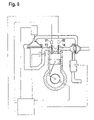
- FIG. 1 shows a first exemplary embodiment of a device of the invention together with the technical environment of the present invention.
- FIG. 2 shows an exemplary embodiment of the method of the present invention for activating the introduction of air.
- FIG. 3 shows an exemplary embodiment of a method of the present invention having one alternative for deactivating the introduction of air.
- FIG. 4 shows another exemplary embodiment of a method of the present invention having one alternative for deactivating the introduction of air.
- FIG. 5 shows an exemplary embodiment that allows the use of the present invention for internal combustion engines having low cylinder numbers and having gas-exchange valves (intake valves, exhaust valves) controlled by camshafts.
- FIG. 6 shows a further exemplary embodiment of the present invention in a modified technical environment that includes a variable valve control.
- FIG. 7 shows a further exemplary embodiment of the present invention starting out from the exemplary embodiment according to FIG. 6 , this exemplary embodiment relating to the prevention of HC emissions after shutoff of the internal combustion engine.
- FIG. 8 shows a flow chart for clarifying the method of the present invention with respect to the prevention of HC emissions.
- Reference numeral 1 in FIG. 1 designates an internal combustion engine having a combustion chamber 2 above a piston 3 and an exhaust-gas turbocharger 4 in an exhaust-gas pipe system 5 as well as having an arrangement 6 for introducing air into induction region 7 of the internal combustion engine.
- Arrangement 6 may be an electric turbocharger that is used in addition to support a conventional exhaust-gas turbocharger 4 .
- Electric turbocharger 6 has a delivery wheel 9 , which is driven via a shaft 8 by an electric motor 10 . In the driven state, delivery wheel 9 feeds air into induction region 7 .
- the arrow designated by reference numeral 11 represents the flow direction of air flowing into induction region 7 .
- the supplied air is conducted via a throttle valve device 12 and open intake valves 13 and exhaust valves 14 through combustion chamber 2 into exhaust-gas pipe system 5 .
- the air flows through an exhaust-gas device 23 , which may be a catalytic converter, and transports excess heat from the exhaust-gas device into the environment. This cooling protects exhaust-gas device 13 from heat build-up during still stand of the internal combustion engine when there is no cooling effect from cooler exhaust gas.
- a control unit 24 e.g. an electronic control device, controls the cooling of the exhaust-gas device in accordance with the exemplary embodiment and/or exemplary method of the present invention during still stand of the internal combustion engine.
- Exhaust-gas analyzer probe 15 may be situated in front of or inside of exhaust-gas device 23 .
- Probe 15 may be a temperature sensor.
- the probe may also be an exhaust-gas probe for recording the concentration of an exhaust-gas component in the exhaust gas, the signals of the probe allowing conclusions regarding temperature.
- the internal resistance of a conventional lambda probe may be used for determining the temperature.
- Control unit 24 controls electric motor 10 during still stand of the internal combustion engine as a function of the formed measurement.
- the representation of FIG. 1 shows intake valve 13 and exhaust valve 14 operated by a camshaft 16 and a camshaft 17 .
- both valves are open, intake valve 13 already being open and exhaust valve 14 still being open.
- This state also designated as a valve overlap occurs in four-stroke engines during transition from the exhaust stroke, during which the combusted gases are expelled from the combustion chamber into exhaust-gas pipe system 5 , to the intake stroke, in which fresh air or a fresh mixture is drawn from induction region 7 into the combustion chamber.
- fresh air may be transported at any time from induction region 7 through combustion chamber 2 into the exhaust-gas pipe region.
- An inductive sensor 19 at camshaft 16 or 17 provides in connection with a camshaft pulse-generating wheel 20 , information as to whether a certain cylinder of the internal combustion engine or its piston is in the first half (induction/compression) or in the second half (combustion/exhaust) of a work cycle.
- a further inductive sensor 18 provides together with a comparatively sensitive sequence of ferromagnetic markings 21 of a crankshaft pulse-generating wheel 22 , information regarding the position of the piston and the camshafts within each half of the work cycle. Since the rotational angle of the crankshaft and the camshafts at which a valve overlap occurs is known, the analysis of the signals of inductive sensors 18 and 19 are able to be used to evaluate whether there is a valve overlap. If this is not the case and the exemplary method of the present invention is to be performed, control unit 24 is able to activate a starter 25 , which rotates the crankshaft via a toothed ring represented as segment 26 and connected in a torsionally fixed manner to the crankshaft to the extent that a valve overlap occurs. For the sake of completion, it is mentioned that rotation of the crankshaft also results in rotation of the camshafts since these shafts are connected to one another for example via toothed belts, chains, or toothed wheels to have synchronous phases.
- FIG. 2 shows an exemplary embodiment of the method of the present invention in the form of functional blocks.
- Parameters P of the internal combustion engine or of the exhaust-gas pipe system are supplied to block 23 to form a measurement T for a temperature in the exhaust-gas pipe system therefrom.
- P may represent the signal of probe 15 .
- P may also represent an ensemble of operating parameters of the internal combustion engine, such as intake air quantity, rotational speed, intake air temperature, etc., from which a measurement for temperature T in the exhaust-gas pipe system is formed in block 23 using a temperature model.
- Measurement T for the temperature in the exhaust-gas pipe system, which is formed in block 23 is compared to a predetermined threshold value Ts in a block 24 . If T is greater than Ts, electric exhaust-gas turbocharger 6 or its electric motor 10 is activated.
- the functional blocks in FIG. 2 as well as the functional blocks in FIGS. 3 through 5 are realized by software modules and hardware components, such as output stages, in control unit 14 .
- FIG. 3 shows a further embodiment of the method of the present invention.
- FIG. 3 has a further block 25 , in which temperature T or measurement T for the temperature in the exhaust-gas pipe system is compared with a further threshold value Ts_end.
- the function of this comparison in block 25 is that electric turbocharger 6 or its electric motor 10 is deactivated again when temperature T is less than threshold value Ts_end.
- Ts_end is less than threshold value Ts.
- FIG. 4 A further example of a deactivation of the introduction of air into induction region 7 is shown in FIG. 4 .
- Temperature T or measurement T for a temperature in the exhaust-gas pipe region is subsequently supplied not only to block 24 but also at the same time to block 26 .
- Block 26 determines as a function of value T a threshold value ts, which is supplied to block 28 and represents a desired on-period of the electric turbocharger.
- the output signal of block 24 which activates the electric turbocharger, is supplied in parallel to a block 27 and triggers a counting operation there.
- the result of this counting operation is supplied as a time variable t to block 28 , in which it is compared to threshold value ts.
- block 28 deactivates electric exhaust-gas turbocharger 6 or its electric motor 10 and thus ends the introduction of air into induction region 7 of internal combustion engine 1 .
- This corresponds with a time control of the air supply, the time span of the air supply being able to be predefined in a fixed manner or, as shown here, being able to be predefined as a function of the value of temperature T.
- an extension of the time span with air supply with increasing values of temperature T is advantageous.
- FIG. 5 represents a program module via which control unit 14 controls starter 21 as necessary to produce a valve overlap.
- Signals from inductive sensors 18 and 19 of the crankshaft and the camshaft are supplied to a block 29 for this purpose.
- comparison parameters V e.g. the known angle positions at which a valve overlap is present, from a block 30 , e.g. a memory, are supplied to block 29 .
- block 29 controls starter 21 in order to generate a valve overlap via a rotation of the crankshaft and the camshafts that are coupled with the crankshaft in a rotationally synchronous manner.
- FIG. 6 shows a variation of a technical environment in which the exemplary embodiment and/or exemplary method of the present invention may be used.
- the variation consists in that intake valves 13 and exhaust valves 14 are not operated by camshafts but, for example, by electrohydraulic actuators 31 and 32 .
- valves 13 and 14 are able to be opened independently of the position of the crankshaft and the piston during still stand of the internal combustion engine to allow an air flow from induction region 7 into exhaust-gas pipe region 5 of internal combustion engine 1 .
- Such a fully variable valve control is referred to in U.S. Pat. No. 4,009,695, for example.
- a so-called throttle-free load control is also referred to in German patent document no. 195 01 386 (U.S. Pat. No. 5,588,411).
- Such a throttle-free load control distinguishes itself in that at least the intake valves are able to be opened via a variable stroke. Given a request for high torques, a large stroke is used to achieve a substantial combustion chamber filling and given a request for low torques, e.g. during idling of the internal combustion engine, a very small valve stroke is used to achieve a minimal combustion chamber filling.
- valve stroke of the intake valves may be more widely open during introduction of the fresh air into induction region 7 of internal combustion engine 1 than the minimal stroke requires in order to reduce the flow resistance of the internal combustion engine.
- the intake valves may be maximally opened in this case.
- FIG. 7 shows a crankcase ventilation 100 , a tank ventilation 105 having a tank ventilation valve 110 , and an injection valve 115 .
- Injection valve 115 is positioned in this context in induction region 7 of the internal combustion engine so that the injection is manifold injection. Alternatively, the injection may also be performed directly into combustion chamber 2 .
- Tank ventilation 105 and crankcase ventilation 100 are also performed into induction region 7 .
- the process of the method of the present invention with respect to the prevention of HC emissions is shown by way of example in a flow chart according to FIG. 8 .
- the program is implemented in control unit 24 , for example.
- a check is performed at program point 200 to determine whether internal combustion engine 1 was shut off and is at a still stand. If this is the case, the program branches to a program point 205 , otherwise the program branches back to program point 200 .
- a speed sensor not shown in the figures that determines the speed of the internal combustion engine and transmits this to control unit 24 may be used for this purpose. If the recorded rotational speed is not equal to zero, the control unit detects still stand of internal combustion engine 1 , otherwise internal combustion engine 1 is still running.
- control unit 24 checks on the basis of the measured or modeled catalytic converter temperature whether the catalytic converter temperature is greater than predetermined threshold value Ts. If this is the case, the program branches to a program point 210 , otherwise the program is exited and the catalytic converter temperature is considered to be insufficient for complete combustion of the HC residues or emissions.
- Predetermined threshold value Ts may be selected to be 300° C., for example. It is assumed in this context that exhaust-gas device 23 is configured as a catalytic converter.
- these indications may be an engine temperature, a distance traveled, or an operating time of the engine since the last start.
- control unit 24 causes electric motor 10 to be switched on or controlled in a timed manner at a minimal torque.
- valves 13 and 14 are opened in the manner described in FIG. 6 to allow the air flow from induction region 7 through internal combustion engine 1 into exhaust-gas pipe region 5 . If there is no such fully variable valve control but instead valves 13 and 14 are operated via camshafts 16 and 17 according to FIG. 1 , it must be ensured in the manner described in FIG. 1 that there is a valve overlap in order to allow the desired air flow from induction region 7 to exhaust-gas pipe region 5 .
- control unit 24 checks whether an engine temperature of internal combustion engine 1 is less than a predefined threshold value Tm.
- the predefined threshold value may be 10° C., for example. Additionally or alternatively, control unit 24 may check whether the measured or modeled catalytic converter temperature is less than further threshold value Ts_end. Further threshold value Ts_end may be selected to be 250° C., for example. Additionally or alternatively, control unit 24 may check whether the time elapsed since electric motor 10 was switched on exceeds threshold value ts. If one of the three indicated conditions is met, the program branches to a program point 220 , otherwise the program branches back to program point 215 .
- threshold value ts for the elapsed time since activation of electric motor 10 is to be selected such that combustion of the HC residues that is as complete as possible is ensured.
- control unit 24 causes electric motor 24 to be switched off, thereby ending the air flow from induction region 7 through internal combustion engine 1 to exhaust-gas pipe region 5 . As a result, further combustion of HC residues is prevented.
- the program is subsequently exited.
- the program is able to be restarted for every activated internal combustion engine.
- the HC emissions are greatest following shutoff of internal combustion engine 1 , especially when internal combustion engine 1 is still warm. This is due among other things to crankcase ventilation 100 . If a lighter air flow is generated with the help of electric motor 10 and as such electric turbocharger 6 , the HC emissions are transported in the direction of exhaust-gas pipe system 5 and are converted in catalytic converter 23 . Several minutes after activation of electric turbocharger 6 , the HC emissions are removed from induction region 7 in this manner, and electric turbocharger 6 is able to be switched back off once threshold value ts has elapsed.
Landscapes
- Engineering & Computer Science (AREA)
- Chemical & Material Sciences (AREA)
- Combustion & Propulsion (AREA)
- Mechanical Engineering (AREA)
- General Engineering & Computer Science (AREA)
- Output Control And Ontrol Of Special Type Engine (AREA)
- Exhaust Silencers (AREA)
- Exhaust Gas After Treatment (AREA)
- Electrical Control Of Air Or Fuel Supplied To Internal-Combustion Engine (AREA)
- Combined Controls Of Internal Combustion Engines (AREA)
Applications Claiming Priority (5)
| Application Number | Priority Date | Filing Date | Title |
|---|---|---|---|
| DE10205969.1 | 2002-02-14 | ||
| DE10205969 | 2002-02-14 | ||
| DE10235194.5 | 2002-08-01 | ||
| DE10235194A DE10235194A1 (de) | 2002-02-14 | 2002-08-01 | Verfahren und Vorrichtung zum Betreiben eines Verbrennungsmotors |
| PCT/DE2003/000331 WO2003069135A1 (de) | 2002-02-14 | 2003-02-06 | Verfahren und vorrichtung zum betreiben eines verbrennungsmotors |
Publications (2)
| Publication Number | Publication Date |
|---|---|
| US20050091965A1 US20050091965A1 (en) | 2005-05-05 |
| US7213396B2 true US7213396B2 (en) | 2007-05-08 |
Family
ID=27735670
Family Applications (1)
| Application Number | Title | Priority Date | Filing Date |
|---|---|---|---|
| US10/504,788 Expired - Fee Related US7213396B2 (en) | 2002-02-14 | 2003-02-06 | Method and device for operating an internal combustion engine |
Country Status (5)
| Country | Link |
|---|---|
| US (1) | US7213396B2 (de) |
| EP (1) | EP1478830B1 (de) |
| JP (1) | JP2005517852A (de) |
| DE (1) | DE50301615D1 (de) |
| WO (1) | WO2003069135A1 (de) |
Cited By (7)
| Publication number | Priority date | Publication date | Assignee | Title |
|---|---|---|---|---|
| US20070163246A1 (en) * | 2006-01-16 | 2007-07-19 | Robert Wassmur | Method and arrangement for cooling an exhaust system |
| US20100263639A1 (en) * | 2009-04-20 | 2010-10-21 | Ford Global Technologies, Llc | Engine Control Method and System |
| US20110179780A1 (en) * | 2007-01-29 | 2011-07-28 | Toyota Jidosha Kabushiki Kaisha | Secondary air supply device for internal combustion engine and control method of the secondary air supply device |
| US20140216422A1 (en) * | 2013-02-06 | 2014-08-07 | Hyundai Motor Company | Method of controlling engine |
| US20180202349A1 (en) * | 2017-01-19 | 2018-07-19 | Ford Global Technologies, Llc | Systems and method for charge air cooler de-icing |
| US20190353108A1 (en) * | 2018-05-16 | 2019-11-21 | Hyundai Motor Company | Hybrid vehicle and method for controlling the same |
| DE102019203061A1 (de) * | 2019-03-06 | 2020-09-10 | Ford Global Technologies, Llc | Verfahren zum Regenerieren eines NOx-Speicherkatalysators einer Abgasnachbehandlungsvorrichtung |
Families Citing this family (8)
| Publication number | Priority date | Publication date | Assignee | Title |
|---|---|---|---|---|
| JP2006327363A (ja) * | 2005-05-25 | 2006-12-07 | Toyota Motor Corp | 車両の制御装置 |
| JP4692118B2 (ja) * | 2005-07-15 | 2011-06-01 | トヨタ自動車株式会社 | エンジンの制御装置 |
| US20070044468A1 (en) * | 2005-09-01 | 2007-03-01 | Stm Power, Inc. | Energy recovery system for combustible vapors |
| US9631548B2 (en) * | 2012-10-16 | 2017-04-25 | Ford Global Technologies, Llc | Internal combustion engine which can be operated with liquid and with gaseous fuel and a method for operating an internal combustion engine of this kind |
| WO2014158077A1 (en) * | 2013-03-26 | 2014-10-02 | Kasi Technologies Ab | Supercharging system and method for operating a supercharging system |
| AT517166B1 (de) * | 2015-05-11 | 2017-05-15 | Ge Jenbacher Gmbh & Co Og | Verfahren zum Spülen eines Abgasreinigungssystems |
| JP6650762B2 (ja) * | 2016-01-15 | 2020-02-19 | 三菱重工業株式会社 | 内燃機関、内燃機関の制御装置及び方法 |
| JP7831452B2 (ja) * | 2023-09-27 | 2026-03-17 | トヨタ自動車株式会社 | エンジンシステムの制御装置 |
Citations (17)
| Publication number | Priority date | Publication date | Assignee | Title |
|---|---|---|---|---|
| US3751916A (en) * | 1970-12-29 | 1973-08-14 | Toyo Kogyo Co | Exhaust gas purifying system for use in internal combustion engine |
| US3931710A (en) * | 1972-11-10 | 1976-01-13 | Deutsche Vergaser Gmbh & Co. Kommanditgesellschaft | Method and installation for the predetermined addition of secondary air for the optimum combustion of exhaust gases of internal combustion engines |
| US3967929A (en) * | 1973-01-13 | 1976-07-06 | Nissan Motor Co., Ltd. | Exhaust gas purifying system |
| US4009695A (en) | 1972-11-14 | 1977-03-01 | Ule Louis A | Programmed valve system for internal combustion engine |
| US4257227A (en) * | 1977-12-26 | 1981-03-24 | Honda Giken Kogyo Kabushiki Kaisha | Secondary air controlling apparatus for internal combustion engines |
| US4484441A (en) * | 1982-07-01 | 1984-11-27 | Honda Giken Kogyo Kabushiki Kaisha | Exhaust gas purification apparatus |
| US4534173A (en) * | 1981-10-19 | 1985-08-13 | Honda Giken Kogyo Kabushiki Kaisha | Means for supplying a secondary air in an internal combustion engine which is provided with a turbo charger |
| JPH01190927A (ja) * | 1988-01-22 | 1989-08-01 | Hitachi Ltd | 内燃機関の空気量制御装置 |
| US5233830A (en) * | 1990-05-28 | 1993-08-10 | Toyota Jidosha Kabushiki Kaisha | Exhaust gas purification system for an internal combustion engine |
| DE4400536A1 (de) | 1993-01-11 | 1994-07-14 | Fuji Heavy Ind Ltd | Motorabgasvorrichtung |
| DE19501386A1 (de) | 1995-01-18 | 1996-08-01 | Meta Motoren Energietech | Verfahren zum Steuern einer fremdgezündeten, mit einer Kraftstoffeinspritzanlage ausgerüsteten Kolbenbrennkraftmaschine |
| US5590521A (en) | 1993-11-10 | 1997-01-07 | Robert Bosch Gmbh | Method and device for forming a simulated signal of the temperature of the exhaust gas, exhaust gas sensor or catalytic converter |
| DE19608060C1 (de) | 1996-03-02 | 1997-07-10 | Frank Dziobek | Verfahren zur Verhinderung von Stillstandskorrosion in Abgasanlagen von Kraftfahrzeugen |
| DE19705421C1 (de) | 1997-02-13 | 1998-05-20 | Daimler Benz Ag | Verfahren zur Entgiftung von Abgasen einer Kolbenbrennkraftmaschine |
| DE19735455C1 (de) | 1997-08-16 | 1998-11-19 | Daimler Benz Ag | Verfahren zum Reduzieren von Abgasemissionen beim Abstellen einer Brennkraftmaschine |
| EP1070837A2 (de) | 1999-07-23 | 2001-01-24 | Steyr-Nutzfahrzeuge Aktiengesellschaft | Vorrichtung und Verfahren zur Leistungssteigerung einer mittels Abgasturboladers aufgeladenen Brennkraftmaschine |
| US6293236B1 (en) | 1999-02-24 | 2001-09-25 | Roberto Forero De Francisco | Breathing system for internal combustion engines, using dual duty (alternatively exhaust-intake) valves and a forced air supply |
-
2003
- 2003-02-06 WO PCT/DE2003/000331 patent/WO2003069135A1/de not_active Ceased
- 2003-02-06 DE DE50301615T patent/DE50301615D1/de not_active Expired - Lifetime
- 2003-02-06 JP JP2003568229A patent/JP2005517852A/ja not_active Withdrawn
- 2003-02-06 EP EP03706285A patent/EP1478830B1/de not_active Expired - Lifetime
- 2003-02-06 US US10/504,788 patent/US7213396B2/en not_active Expired - Fee Related
Patent Citations (18)
| Publication number | Priority date | Publication date | Assignee | Title |
|---|---|---|---|---|
| US3751916A (en) * | 1970-12-29 | 1973-08-14 | Toyo Kogyo Co | Exhaust gas purifying system for use in internal combustion engine |
| US3931710A (en) * | 1972-11-10 | 1976-01-13 | Deutsche Vergaser Gmbh & Co. Kommanditgesellschaft | Method and installation for the predetermined addition of secondary air for the optimum combustion of exhaust gases of internal combustion engines |
| US4009695A (en) | 1972-11-14 | 1977-03-01 | Ule Louis A | Programmed valve system for internal combustion engine |
| US3967929A (en) * | 1973-01-13 | 1976-07-06 | Nissan Motor Co., Ltd. | Exhaust gas purifying system |
| US4257227A (en) * | 1977-12-26 | 1981-03-24 | Honda Giken Kogyo Kabushiki Kaisha | Secondary air controlling apparatus for internal combustion engines |
| US4534173A (en) * | 1981-10-19 | 1985-08-13 | Honda Giken Kogyo Kabushiki Kaisha | Means for supplying a secondary air in an internal combustion engine which is provided with a turbo charger |
| US4484441A (en) * | 1982-07-01 | 1984-11-27 | Honda Giken Kogyo Kabushiki Kaisha | Exhaust gas purification apparatus |
| JPH01190927A (ja) * | 1988-01-22 | 1989-08-01 | Hitachi Ltd | 内燃機関の空気量制御装置 |
| US5233830A (en) * | 1990-05-28 | 1993-08-10 | Toyota Jidosha Kabushiki Kaisha | Exhaust gas purification system for an internal combustion engine |
| DE4400536A1 (de) | 1993-01-11 | 1994-07-14 | Fuji Heavy Ind Ltd | Motorabgasvorrichtung |
| US5590521A (en) | 1993-11-10 | 1997-01-07 | Robert Bosch Gmbh | Method and device for forming a simulated signal of the temperature of the exhaust gas, exhaust gas sensor or catalytic converter |
| DE19501386A1 (de) | 1995-01-18 | 1996-08-01 | Meta Motoren Energietech | Verfahren zum Steuern einer fremdgezündeten, mit einer Kraftstoffeinspritzanlage ausgerüsteten Kolbenbrennkraftmaschine |
| US5588411A (en) | 1995-01-18 | 1996-12-31 | Meta Motoren- Und Energie-Technik Gmbh | Method for controlling an internal combustion engine with external ignition system and with a fuel injection system |
| DE19608060C1 (de) | 1996-03-02 | 1997-07-10 | Frank Dziobek | Verfahren zur Verhinderung von Stillstandskorrosion in Abgasanlagen von Kraftfahrzeugen |
| DE19705421C1 (de) | 1997-02-13 | 1998-05-20 | Daimler Benz Ag | Verfahren zur Entgiftung von Abgasen einer Kolbenbrennkraftmaschine |
| DE19735455C1 (de) | 1997-08-16 | 1998-11-19 | Daimler Benz Ag | Verfahren zum Reduzieren von Abgasemissionen beim Abstellen einer Brennkraftmaschine |
| US6293236B1 (en) | 1999-02-24 | 2001-09-25 | Roberto Forero De Francisco | Breathing system for internal combustion engines, using dual duty (alternatively exhaust-intake) valves and a forced air supply |
| EP1070837A2 (de) | 1999-07-23 | 2001-01-24 | Steyr-Nutzfahrzeuge Aktiengesellschaft | Vorrichtung und Verfahren zur Leistungssteigerung einer mittels Abgasturboladers aufgeladenen Brennkraftmaschine |
Cited By (12)
| Publication number | Priority date | Publication date | Assignee | Title |
|---|---|---|---|---|
| US20070163246A1 (en) * | 2006-01-16 | 2007-07-19 | Robert Wassmur | Method and arrangement for cooling an exhaust system |
| US20110179780A1 (en) * | 2007-01-29 | 2011-07-28 | Toyota Jidosha Kabushiki Kaisha | Secondary air supply device for internal combustion engine and control method of the secondary air supply device |
| US8453437B2 (en) * | 2007-01-29 | 2013-06-04 | Toyota Jidosha Kabushiki Kaisha | Secondary air supply device for internal combustion engine and control method of the secondary air supply device |
| US20100263639A1 (en) * | 2009-04-20 | 2010-10-21 | Ford Global Technologies, Llc | Engine Control Method and System |
| US20140216422A1 (en) * | 2013-02-06 | 2014-08-07 | Hyundai Motor Company | Method of controlling engine |
| US20180202349A1 (en) * | 2017-01-19 | 2018-07-19 | Ford Global Technologies, Llc | Systems and method for charge air cooler de-icing |
| US10563571B2 (en) * | 2017-01-19 | 2020-02-18 | Ford Global Technologies, Llc | Systems and method for charge air cooler de-icing |
| US20190353108A1 (en) * | 2018-05-16 | 2019-11-21 | Hyundai Motor Company | Hybrid vehicle and method for controlling the same |
| US10801427B2 (en) * | 2018-05-16 | 2020-10-13 | Hyundai Motor Company | Hybrid vehicle and method for controlling the same |
| DE102019203061A1 (de) * | 2019-03-06 | 2020-09-10 | Ford Global Technologies, Llc | Verfahren zum Regenerieren eines NOx-Speicherkatalysators einer Abgasnachbehandlungsvorrichtung |
| US11220941B2 (en) | 2019-03-06 | 2022-01-11 | Ford Global Technologies, Llc | Methods and systems for an aftertreatment system |
| DE102019203061B4 (de) | 2019-03-06 | 2024-10-24 | Ford Global Technologies, Llc | Verfahren zum Regenerieren eines NOx-Speicherkatalysators einer Abgasnachbehandlungsvorrichtung |
Also Published As
| Publication number | Publication date |
|---|---|
| EP1478830A1 (de) | 2004-11-24 |
| DE50301615D1 (de) | 2005-12-15 |
| EP1478830B1 (de) | 2005-11-09 |
| JP2005517852A (ja) | 2005-06-16 |
| WO2003069135A1 (de) | 2003-08-21 |
| US20050091965A1 (en) | 2005-05-05 |
Similar Documents
| Publication | Publication Date | Title |
|---|---|---|
| US7213396B2 (en) | Method and device for operating an internal combustion engine | |
| RU2607707C2 (ru) | Способ диагностики системы рециркуляции отработавших газов (варианты) и система рециркуляции отработавших газов | |
| JP6275181B2 (ja) | 電動ウェイストゲートバルブ制御装置 | |
| US8666640B2 (en) | Control apparatus and control method for internal combustion engine | |
| US8881713B2 (en) | Method and system for humidity sensor diagnostics | |
| RU2626879C2 (ru) | Способ для двигателя (варианты) | |
| RU2665347C2 (ru) | Электрическая калибровка датчика системы управления перепускной заслонкой с обнаружением концевого упора | |
| US8639411B2 (en) | Method to diagnose a fault of an oil piston cooling jets valve | |
| JP4159918B2 (ja) | 圧縮着火式内燃機関の燃料カット制御装置 | |
| CN103573440B (zh) | 相对空气湿度的间接测量 | |
| US20020000087A1 (en) | Method and arrangement for checking catalytic converter heating measures in an internal combustion enqine | |
| JP5847857B2 (ja) | 内燃機関のバルブの基準位置学習装置 | |
| US20170089284A1 (en) | Control apparatus of engine | |
| WO2013014789A1 (ja) | 内燃機関の制御装置 | |
| US10012164B2 (en) | Control apparatus of engine | |
| KR20090031244A (ko) | 내연기관 작동 방법 및 장치 | |
| JP5447033B2 (ja) | 内燃機関の制御装置 | |
| JP2003090215A (ja) | 内燃機関における排ガス後処理のための方法及び装置 | |
| US6286993B1 (en) | Method for forming a signal representing the instantaneous temperature of a catalytic converter | |
| JP5081117B2 (ja) | 過給機付エンジンの制御装置 | |
| GB2491110A (en) | Method of operating an internal combustion engine having crankshaft position sensor correction means | |
| GB2490942A (en) | Controlling an electrically driven compressor | |
| CN115199389A (zh) | 用于检测传感器偏移的系统和方法 | |
| US12044163B1 (en) | Modeling compressor pressure drop for turbocharger incorporating cold light off catalyst | |
| US11313287B2 (en) | System and method for gaspath actuators |
Legal Events
| Date | Code | Title | Description |
|---|---|---|---|
| AS | Assignment |
Owner name: ROBERT BOSCH GMBH, GERMANY Free format text: ASSIGNMENT OF ASSIGNORS INTEREST;ASSIGNORS:RIES-MUELLER, KLAUS;BAEUERLE, MICHAEL;BLUMENSTOCK, ANDREAS;REEL/FRAME:016233/0653;SIGNING DATES FROM 20040504 TO 20040514 |
|
| FPAY | Fee payment |
Year of fee payment: 4 |
|
| REMI | Maintenance fee reminder mailed | ||
| LAPS | Lapse for failure to pay maintenance fees | ||
| STCH | Information on status: patent discontinuation |
Free format text: PATENT EXPIRED DUE TO NONPAYMENT OF MAINTENANCE FEES UNDER 37 CFR 1.362 |
|
| STCH | Information on status: patent discontinuation |
Free format text: PATENT EXPIRED DUE TO NONPAYMENT OF MAINTENANCE FEES UNDER 37 CFR 1.362 |
|
| FP | Lapsed due to failure to pay maintenance fee |
Effective date: 20150508 |