US7144192B2 - Self-propelled road milling machine - Google Patents
Self-propelled road milling machine Download PDFInfo
- Publication number
- US7144192B2 US7144192B2 US10/511,031 US51103104A US7144192B2 US 7144192 B2 US7144192 B2 US 7144192B2 US 51103104 A US51103104 A US 51103104A US 7144192 B2 US7144192 B2 US 7144192B2
- Authority
- US
- United States
- Prior art keywords
- milling
- base body
- gear unit
- reduction gear
- roll base
- Prior art date
- Legal status (The legal status is an assumption and is not a legal conclusion. Google has not performed a legal analysis and makes no representation as to the accuracy of the status listed.)
- Expired - Lifetime
Links
- 238000003801 milling Methods 0.000 title claims abstract description 189
- 230000008878 coupling Effects 0.000 description 4
- 238000010168 coupling process Methods 0.000 description 4
- 238000005859 coupling reaction Methods 0.000 description 4
- 238000006243 chemical reaction Methods 0.000 description 3
- 238000010276 construction Methods 0.000 description 3
- 230000004323 axial length Effects 0.000 description 2
- 238000002485 combustion reaction Methods 0.000 description 2
- 208000031872 Body Remains Diseases 0.000 description 1
- 238000010516 chain-walking reaction Methods 0.000 description 1
- 230000018109 developmental process Effects 0.000 description 1
- 238000003754 machining Methods 0.000 description 1
- 238000000034 method Methods 0.000 description 1
- 230000003746 surface roughness Effects 0.000 description 1
Images

Classifications
-
- E—FIXED CONSTRUCTIONS
- E01—CONSTRUCTION OF ROADS, RAILWAYS, OR BRIDGES
- E01C—CONSTRUCTION OF, OR SURFACES FOR, ROADS, SPORTS GROUNDS, OR THE LIKE; MACHINES OR AUXILIARY TOOLS FOR CONSTRUCTION OR REPAIR
- E01C23/00—Auxiliary devices or arrangements for constructing, repairing, reconditioning, or taking-up road or like surfaces
- E01C23/06—Devices or arrangements for working the finished surface; Devices for repairing or reconditioning the surface of damaged paving; Recycling in place or on the road
- E01C23/08—Devices or arrangements for working the finished surface; Devices for repairing or reconditioning the surface of damaged paving; Recycling in place or on the road for roughening or patterning; for removing the surface down to a predetermined depth high spots or material bonded to the surface, e.g. markings; for maintaining earth roads, clay courts or like surfaces by means of surface working tools, e.g. scarifiers, levelling blades
- E01C23/085—Devices or arrangements for working the finished surface; Devices for repairing or reconditioning the surface of damaged paving; Recycling in place or on the road for roughening or patterning; for removing the surface down to a predetermined depth high spots or material bonded to the surface, e.g. markings; for maintaining earth roads, clay courts or like surfaces by means of surface working tools, e.g. scarifiers, levelling blades using power-driven tools, e.g. vibratory tools
- E01C23/088—Rotary tools, e.g. milling drums
Definitions
- the invention relates to a self-propelled road milling machine.
- the milling roll drive is effected hydrostatically by arranging hydraulic motors at both sides of the milling roll.
- the connection between the segments is a simple plug-in connection that only permits an insufficient centering of the milling rotor. Because a drive device is provided at both sides, it is not possible to mill near the edges.
- a roll housing of variable width is required the construction of which is very complicated.
- U.S. Pat. No. 4,720,207 describes milling tube segments mounted on a roll base body.
- a side ring segment is attached at one side first.
- the milling tube segments are screwed down thereon, the screw connections being located within the segments.
- the enormous screwing efforts and the fact that the milling depth is restricted because of the constant diameter of the base body when a planet gear is integrated in the base body are disadvantageous.
- This gear arrangement with a gear unit the outer diameter of which is only slightly smaller than that of the milling tube is required to permit a flush milling. From the section of the milling roll in which the reduction gear unit is integrated, an axle stub projects on which further segments with milling tools can be mounted.
- a road milling machine with a machine chassis in which a milling roll is rotatably supported, the milling roll comprising a roll base body driven by a milling roll drive means via a gear unit and alternatively employable coaxial milling tubes adapted to be slid onto the roll base body from one side and being exchangeably mounted and carrying cutting tools on their outer shell surface.
- the reduction gear unit is provided at the input side if the milling tubes extend over the entire working width.
- the roll base body is mounted to a radially projecting flange of the gear housing, a screw connection from the difficultly accessible input side being required.
- the milling tubes almost have to be flush with the null side to permit a milling near the edge.
- the gear unit arranged on the input side would limit the realizable milling depth.
- the reduction gear unit is therefore arranged on the null side of the machine, i.e., on the side where a milling near the edge is possible.
- This has the disadvantage that a drive shaft extending from the input side to the reduction gear unit on the null side is required, which has to be supported and provided with an additional protection tube as protection against damage.
- the reduction gear unit forms a stationary bearing, which, because of the arrangement on the null side, inevitably requires that a movable bearing be arranged on the input side.
- a pivotable lateral plate for the quick exchange of the milling tubes is arranged on the null side, which is less suitable for receiving the high reaction forces of a stationary bearing in axial direction.
- the movable bearing is further located on the difficultly accessible input side on which, e.g., the torsion protection for the movable bearing must be mountable.
- Another disadvantage consists in that the long drive shaft acts like a torsional spring system whereby a rigid drive of the milling roll is not possible and the maximally possible cutting forces are reduced.
- split rings are absolutely necessary, which have to be mounted in a constrained position of the fitter.
- the mounting of the split rings may require to repeatedly change the rotational position of the roll base body, e.g., by 180, whereby the risks of an accident are increased.
- the invention advantageously provides that the reduction gear unit is mounted at the input side, that the reduction gear unit comprises an output element which is mounted on the interior of the input-side lateral plate and whose shell surface forms a seat for milling tube elements that can be slid thereon from the null side, i.e., namely the input-side ends of the milling tubes or radial supporting means for the milling tubes and/or tubular protection means for the output element, and that the roll base body is coupled to the reduction gear unit at the free face of the output element without hindering the milling tube elements in being slid on.
- the reduction gear unit is arranged on the input side, the reduction gear unit comprising a preferably circularly cylindrical housing forming the output element of the reduction gear unit, the roll base body being coupled to the reduction gear unit at the face of the housing.
- the housing has a cross-sectional shape permitting the milling tube or supporting means for the milling tube and/or protection means for the housing to be slid on from the null side, the inner contour of the supporting means or the protection means matching the cross-sectional shape of the housing.
- the housing forms a seat for milling tube ends, supporting and/or protection means being adapted to be slid on from the null side.
- the roll base body has a maximum outer diameter that is not greater than the outer diameter of the housing.
- No split rings for supporting the milling tubes are required which rings, according to prior art, have to be mounted in a constrained position. Coupling the roll base body at the face of the housing advantageously increases the realizable milling depth.
- the one-piece supporting rings according to the invention are adapted to be easily slid onto the housing of the reduction gear unit from the null side and there, they can be fixed at any place in a manner comfortable to the fitter.
- the circularly cylindrical housing of the reduction gear unit whose cross-sectional shape matches the supporting means for the milling tube is able to receive tubular or annular undivided radial supporting means for the milling tube and/or protection means for the housing on its entire axial length.
- the seat for the supporting and/or protection means may also extend over a part of the axial length of the preferably circularly cylindrical housing only.
- the radial supporting means form a movable bearing for the milling tube on the preferably circularly cylindrical housing.
- the tubular or annular radial supporting means positively encompass the preferably circularly cylindrical housing.
- the milling tubes are advantageously centered automatically so that the danger of balance errors is minimized.
- the movable bearing may either be formed between the milling tube and the radial supporting means, e.g., a radial supporting ring, or, if the radial supporting ring is mounted to the milling tube, it may be formed between the radial supporting ring and the seat on the shell surface of the housing.
- the radial supporting ring and a protection tube possibly mounted at the radial supporting ring may slide on the seat surface, namely the shell surface of the housing of the reduction gear unit.
- a centering means for the roll base body may be arranged.
- the centering means consists, for example, of a centering projection either supported on the inner shell surface of the tubular roll base body or is preferably adapted to the inner diameter of a connection flange of the roll base body.
- the free end of the roll base body is unilaterally supported in the easily dismountable lateral plate opposite to the input-side lateral plate.
- the bearing of the roll base body provided on the null side is a movable bearing while a stationary bearing is formed by the reduction gear unit at the input side.
- a protection tube covering the reduction gear unit can be fastened to protect the housing from damage.
- the reduction gear unit comprises at least one reduction stage in an input-side gear unit portion at the site of coupling with the drive means and at least one further reduction stage in the interior of the milling tube in a milling roll-side gear unit portion.
- the division of the reduction gear unit into an input-side gear unit portion at the coupling site of the drive means and a further gear unit portion arranged within the milling roll permits the reduction of the diameter of the cylindrical housing element, whereby a greater milling depth can be achieved with milling tubes of shorter structural length.
- the at least one input-side reduction gear unit stage is arranged so as to be axially offset with respect to the at least one milling roll-side reduction stage.
- the gear unit portions are arranged on both sides of the input-side lateral plate.
- the two gear unit portions are coupled with each other via a gear shaft passing through the lateral plate.
- the easily dismountable lateral plate provided on the null side can be configured so as to be pivotable to exchange the milling tubes.
- the preferably circularly cylindrical housing has an outer diameter of maximally 400 mm, preferably of maximally 350 mm.
- the roll base body comprises a first face-side annular flange adapted to be axially coupled at the face of the housing from the null side as well as a second annular flange radially seated on the roll base body so as to rotate therewith and being adapted to be axially coupled with an annular flange projecting radially inward from the milling tube.
- the torque outputted from the housing of the reduction gear unit as the output element is transferred onto the milling tube by means of the annular flange of the roll base body and the radial annular flange of the milling tube.
- FIG. 1 shows a self-propelled road milling machine
- FIGS. 2 to 5 show embodiments of the invention with milling tubes of different milling widths.
- FIG. 1 a road milling machine 1 is illustrated in which the quick change milling tube system described hereinafter can be employed.
- road milling machines consist of a machine chassis 2 on which an internal combustion engine and a driver's stand are mounted.
- the self-propelled road milling machine comprises height-adjustable lifting columns 3 mounted to the machine chassis 2 , on which supporting wheels or a chain running gear 5 is mounted.
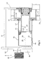
- a milling roll 4 is supported rotatably between lateral plates 12 , 13 of the roll box 11 , which extend orthogonally to the axis of the milling roll and are driven via a drive means 6 supported on the input-side lateral plate 12 and a reduction gear unit 8 .
- the milling roll 4 consists of a roll base body 14 coupled to a housing 26 of the reduction gear unit 8 arranged at the input-side lateral plate 12 and an integral milling tube 10 being exchangeably mounted at the roll base body 14 .
- the roll base body 14 is arranged axially beside the reduction gear unit portion 8 b .
- the roll base body 14 transfers the torque of the reduction gear unit 8 to the respectively used milling tube 10 .
- useable milling tubes 10 of different milling widths and different tool equipment are available for different road machining procedures and are adapted to be quickly changed.
- FIG. 2 shows a first embodiment wherein the drive means 6 is arranged at the input-side lateral plate 12 of which only the pulley 35 is shown in FIG. 2 .
- the combustion engine drives this pulley 35 via, e.g., a joined V-belt.
- the pulley 35 is directly coupled with a first reduction stage of the reduction gear unit 8 in an input-side gear unit portion 8 a .
- Another reduction stage is coupled with the first reduction stage via a gear shaft 28 .
- the second reduction gear unit stage is arranged at a preferably circularly cylindrical housing 26 that is arranged at the milling roll side at the input-side lateral plate 12 .
- the housing 26 forms the output element of the reduction gear unit 8 .
- a roll base body 14 is mounted coaxially to the housing 26 by means of an annular flange 15 provided at the face of the roll base body, the free end of the roll base body 14 being supported in a movable bearing in the lateral plate 13 opposite to the input-side lateral plate 12 .
- the lateral plate 13 is arranged on the null side of the road milling machine which characterizes that side where milling near the edge is possible. At the null side, the distance from the face-side edge of the milling roll 4 to the outside wall of the road milling machine 1 , e.g., the lateral plate 13 , is kept as small as possible.
- the annular flange 15 of the roll base body 14 has the same outer diameter as the cylindrical housing 26 , the inner diameter of the annular flange 15 being seated on a cylindrical centering projection 27 of the housing 26 so that an exactly coaxially oriented position of the roll base body 14 to the reduction gear unit 8 is ensured.
- a second annular flange 17 is provided on the roll base body 14 and serves as a fastening means for the milling tubes 10 .
- annular flanges 19 or other fastening means project radially inward from the inside of the milling tubes 10 and cooperate with the annular flange 17 .
- the annular flange 17 transfers the torque of the roll base body 14 to the milling tube 10 .
- the milling tube 10 is fitted with milling tools 22 , for example, the tool engagement circle 24 of which is indicated by the dashed line in the Figs.
- the maximum milling depth FT is indicated by another dashed line below the lateral plates 12 , 13 .
- the easily dismountable lateral plate 13 is pivotable but, as an alternative, it may also be axially removable.
- the milling tube shown in FIG. 2 has a milling width of 750 mm, for example.
- the free end of the milling tube 10 facing the input side is supported on a supporting ring 29 which is pushed on the housing 26 and fastened there.
- a protection tube 30 mounted to the supporting ring 29 projects, which coaxially surrounds the circularly cylindrical housing 26 and protects the housing 26 of the reduction gear unit 8 from damage.
- a movable bearing is formed, the milling tube 10 being able to slide on the supporting ring 29 .
- the radial supporting ring 29 and the protection tube 30 can be mounted to the milling tube 10 , the common construction of the supporting ring 29 and the protection tube 30 being able to seat on the housing 26 and slide, in the manner of a movable bearing, on the seat of the shell surface 25 of the housing 26 extending in parallel to the gear shaft 28 .
- the roll base body 14 is pre-assembled with the housing 26 of the reduction gear unit 8 and the annular flange 19 . If a change of the milling tube 10 is required because of another task during milling, this change can be effected quickly by dismounting or pivoting the lateral plate 13 first. Then, the screw connections between the milling tube and the annular flange 19 have to be removed whereafter the entire milling tube can be pulled off from the null side. Subsequently, the radial supporting ring 29 along with the supporting tube 30 mounted thereto is pulled off its seat on the housing 26 . They may remain on the housing if the milling tube is only changed for reasons of wear and an equivalent or a different milling tube of the same milling width, e.g., for fine milling, is pushed on again.
- the assembly is effected in reversed order. Accordingly, the supporting ring 29 with the protection tube 30 mounted thereto is first pushed onto the seat on the shell surface 25 of the housing 26 and fixed there. Subsequently, the milling tube 10 can be pushed onto the roll base body 14 and the radial supporting ring 29 .
- the milling tube 10 is screw-connected with the annular flange 19 , wherein it is possible to arrange another annular flange 33 as a face-side cover plate at the end of the milling tube 10 facing the null side in order to prevent dirt from entering into the interior of the milling tube 10 at the face-side end of the milling tube 10 .
- the supporting ring 29 may also be integral with the milling tube 10 , the milling tube 10 , together with the supporting ring 29 , being pushed onto the roll base body 14 .
- the annular flange 19 may also be integral with the milling tube 10 .
- FIG. 3 largely corresponds to the embodiment of FIG. 2 , the milling tube 10 having a maximum milling width between the lateral plates 12 , 13 .
- the radially supporting annular flange 29 is supported on the input-side end of the housing 26 .
- the protection tube 30 mounted to the annular flange 29 is shortened and ends at the face-side end of the housing 26 which faces the input side.
- annular flange 29 along with the protection tube 30 , is mounted to the milling tube 10 and pushed onto the shell surface 25 of the housing 26 along with said milling tube.
- the milling tube 10 is even shorter than in the embodiment of FIG. 2 so that a second radial support of the milling tube 10 may be omitted.
- the protection tube 30 is mounted at the annular flange 19 of the milling tube 10 .
- the milling tube 10 is pushed onto the seat on the shell surface 25 of the housing 26 together with the protection tube 30 .
- both the reduction gear unit and the roll base body 14 may remain unchanged when the milling width is changed, whereas the milling tubes can be mounted or dismounted axially from the null side. No access from the input side is required.
- FIG. 5 shows a milling tube with short milling width which is only screw-connected with the roll base body 14 via the annular flange 19 .
Landscapes
- Engineering & Computer Science (AREA)
- Mechanical Engineering (AREA)
- Mining & Mineral Resources (AREA)
- Architecture (AREA)
- Civil Engineering (AREA)
- Structural Engineering (AREA)
- Road Repair (AREA)
- Milling Processes (AREA)
- Rollers For Roller Conveyors For Transfer (AREA)
- Control Of Position, Course, Altitude, Or Attitude Of Moving Bodies (AREA)
- Grinding Of Cylindrical And Plane Surfaces (AREA)
- Adjustment And Processing Of Grains (AREA)
- Road Paving Machines (AREA)
- Pharmaceuticals Containing Other Organic And Inorganic Compounds (AREA)
- General Details Of Gearings (AREA)
Applications Claiming Priority (5)
| Application Number | Priority Date | Filing Date | Title |
|---|---|---|---|
| DE10230784 | 2002-07-09 | ||
| DE10230784.9 | 2002-07-09 | ||
| DE10232489.1 | 2002-07-18 | ||
| DE10232489A DE10232489A1 (de) | 2002-07-09 | 2002-07-18 | Selbstfahrende Straßenfräsmaschine |
| PCT/EP2003/004517 WO2004005623A1 (de) | 2002-07-09 | 2003-04-30 | Selbstfahrende strassenfräsmaschine |
Publications (2)
| Publication Number | Publication Date |
|---|---|
| US20050158120A1 US20050158120A1 (en) | 2005-07-21 |
| US7144192B2 true US7144192B2 (en) | 2006-12-05 |
Family
ID=30116618
Family Applications (1)
| Application Number | Title | Priority Date | Filing Date |
|---|---|---|---|
| US10/511,031 Expired - Lifetime US7144192B2 (en) | 2002-07-09 | 2003-04-30 | Self-propelled road milling machine |
Country Status (14)
| Country | Link |
|---|---|
| US (1) | US7144192B2 (es) |
| EP (1) | EP1520076B1 (es) |
| JP (1) | JP4190494B2 (es) |
| KR (1) | KR101005186B1 (es) |
| CN (1) | CN100365212C (es) |
| AT (1) | ATE316169T1 (es) |
| AU (1) | AU2003224140B2 (es) |
| BR (1) | BR0311553B1 (es) |
| CA (1) | CA2481779C (es) |
| DE (1) | DE50302240D1 (es) |
| ES (1) | ES2255672T3 (es) |
| MX (1) | MXPA04012008A (es) |
| RU (1) | RU2308561C2 (es) |
| WO (1) | WO2004005623A1 (es) |
Cited By (21)
| Publication number | Priority date | Publication date | Assignee | Title |
|---|---|---|---|---|
| USD626573S1 (en) * | 2007-08-14 | 2010-11-02 | Wirtgen Gmbh | Road milling machine |
| USD635158S1 (en) * | 2010-03-16 | 2011-03-29 | Wirtgen Gmbh | Body panels for a construction machine |
| US20110089746A1 (en) * | 2009-04-10 | 2011-04-21 | Kennametal Inc. | Rotatable cutting tool-tool holder-base assembly |
| US20110089747A1 (en) * | 2009-04-10 | 2011-04-21 | Kennametal Inc. | Retention assembly for cutting bit |
| US20110115278A1 (en) * | 2006-03-31 | 2011-05-19 | Wirtgen Gmbh | Milling Drum For A Construction Machine, Construction Machine As Well As Gearbox Unit For A Milling Drum |
| US20110148177A1 (en) * | 2009-12-18 | 2011-06-23 | Wirtgen Gmbh | Automotive Road Milling Machine |
| USD642599S1 (en) | 2010-10-12 | 2011-08-02 | Wirtgen Gmbh | Body panels for a construction machine |
| USD650396S1 (en) | 2010-11-03 | 2011-12-13 | Joseph Vogele Ag | Feeder for a road paving machine |
| USD660876S1 (en) * | 2010-08-09 | 2012-05-29 | Joseph Vögele AG | Feeder for a road paving machine |
| US20140015304A1 (en) * | 2012-07-16 | 2014-01-16 | Caterpillar Paving Products Inc. | Chamber for milling machine |
| US20150137577A1 (en) * | 2006-12-22 | 2015-05-21 | Wirtgen Gmbh | Road Milling Machine And Method For Measuring The Milling Depth |
| USD755859S1 (en) * | 2014-08-12 | 2016-05-10 | Bomag Gmbh | Milling machine |
| USD774562S1 (en) * | 2014-07-22 | 2016-12-20 | Bomag Gmbh | Cold milling machine |
| USD774561S1 (en) * | 2014-01-24 | 2016-12-20 | Bomag Gmbh | Cold milling machine |
| US9803325B2 (en) | 2009-03-25 | 2017-10-31 | Wirtgen Gmbh | Ejector unit for a road milling machine or the like |
| USD866618S1 (en) * | 2018-03-16 | 2019-11-12 | Wirtgen Gmbh | Body panels for a road milling machine |
| US11313087B2 (en) * | 2017-05-23 | 2022-04-26 | Wirtgen Gmbh | Earth working machine having a rotatable working apparatus axially positionally retainable with high tightening torque by means of a central bolt arrangement, and method for establishing and releasing such retention |
| US11674273B2 (en) | 2021-10-06 | 2023-06-13 | Caterpillar Paving Products Inc. | Milling drum with alignment interface |
| USD1061626S1 (en) * | 2024-03-20 | 2025-02-11 | Hunan Sany Zhongyi Machinery Co., Ltd. | Pavement milling machine |
| USD1062803S1 (en) * | 2023-10-25 | 2025-02-18 | Hunan Sany Zhongyi Machinery Co., Ltd. | Pavement milling machine |
| US12486626B2 (en) | 2023-07-19 | 2025-12-02 | Caterpillar Paving Products Inc. | Quick change rotor alignment feature |
Families Citing this family (15)
| Publication number | Priority date | Publication date | Assignee | Title |
|---|---|---|---|---|
| DE102007019202B4 (de) * | 2007-04-20 | 2015-05-21 | Wirtgen Gmbh | Selbstfahrende Baumaschine, inbesondere Straßenfräsmaschine, Recycler oder Stabilisierer |
| WO2010003436A1 (en) | 2008-07-09 | 2010-01-14 | Marini S.P.A. | Road milling machine with replaceable milling drum for different cutting widths |
| DE102009014730B3 (de) * | 2009-03-25 | 2010-10-28 | Wirtgen Gmbh | Auswerfer bzw. Auswerfereinheit für eine Straßenfräsmaschine oder dergleichen |
| US8256847B2 (en) * | 2010-11-30 | 2012-09-04 | Hall David R | Rotational milling chamber |
| DE102011108016A1 (de) * | 2011-07-19 | 2013-01-24 | Liebherr-Components Biberach Gmbh | Selbstfahrender Oberflächenfräser |
| DE102013208645B4 (de) * | 2013-05-10 | 2018-01-11 | Wirtgen Gmbh | Vorrichtung, insbesondere Kleinfräse, zum Bearbeiten von Straßenoberflächen |
| DE102013013304A1 (de) * | 2013-08-12 | 2015-02-12 | Wirtgen Gmbh | Selbstfahrende Baumaschine zum Bearbeiten von Fahrbahnen oder Bodenoberflächen und Verfahren zum Kühlen der Fräswerkzeuge einer Fräswalze einer selbstfahrenden Baumaschine |
| CN105178145B (zh) * | 2015-09-07 | 2018-01-12 | 南陵旺科知识产权运营有限公司 | 一种轻便可调压型自行进轧路装置 |
| DE102017208775A1 (de) * | 2017-05-23 | 2018-11-29 | Wirtgen Gmbh | Bodenbearbeitungsmaschine, deren Arbeitsvorrichtung mit einem Bord-Aktuator aus ihrer Betriebsposition verlagerbar ist |
| CN111094698A (zh) * | 2017-07-21 | 2020-05-01 | 路科公司 | 用于铣刨机的切割器滚筒和辅助滚筒驱动组件的驱动带脱离 |
| US10787775B2 (en) * | 2017-07-21 | 2020-09-29 | Roadtec, Inc. | Auxiliary drum drive assembly for milling machine |
| CN109112930B (zh) * | 2018-07-25 | 2020-11-20 | 温州澳鼎建材有限公司 | 一种道路施工专用洒水碾压车 |
| KR102259506B1 (ko) | 2019-10-15 | 2021-06-02 | 한국도로공사 | 노면절삭기의 먼지제거장치 |
| DE102020111311B4 (de) * | 2020-04-24 | 2023-07-27 | Wirtgen Gmbh | Wechselaggregat zur texturierenden Bodenoberflächenbearbeitung und Straßenbaumaschine mit einem solchen Wechselaggregat |
| IT202000013528A1 (it) | 2020-06-08 | 2021-12-08 | Seppi M S P A | Macchina con un rotore portautensili cavo cilindrico |
Citations (11)
| Publication number | Priority date | Publication date | Assignee | Title |
|---|---|---|---|---|
| US3072391A (en) * | 1960-06-21 | 1963-01-08 | James F Mcdarrah | Disintegrating machine having cutting and impact action |
| US4614379A (en) * | 1982-09-04 | 1986-09-30 | Reinhard Wirtgen | Apparatus for roughening road surfaces |
| US4704045A (en) | 1985-10-11 | 1987-11-03 | Taylor Thomas M | Apparatus and method for pulverizing asphalt |
| US4720207A (en) | 1986-08-29 | 1988-01-19 | Koehring Company | Segmented rotor |
| US4852946A (en) * | 1982-04-15 | 1989-08-01 | Alfred Hackmack | Surface working accessory and method |
| US5395417A (en) * | 1993-01-26 | 1995-03-07 | Double T Equipment Manufacturing Ltd. | Apparatus and process used in working windrowed ingredients to produce pre-wet cycle mushroom compost |
| US5505598A (en) | 1994-07-29 | 1996-04-09 | Wirtgen America, Inc. | Milling machine with multi-width cutter |
| US5893677A (en) * | 1995-02-12 | 1999-04-13 | Wirtgen Gmbh | Roadworking machine |
| WO2001004422A1 (de) | 1999-07-14 | 2001-01-18 | Wirtgen Gmbh | Baumaschine sowie fräswalze |
| US6210071B1 (en) * | 1999-09-27 | 2001-04-03 | Astec Industries, Inc. | Method and apparatus for cutting rumble strips in a roadway |
| US6547484B2 (en) * | 2001-02-14 | 2003-04-15 | Dustrol, Inc. | Apparatus for cutting rumble strips in a road surface |
Family Cites Families (5)
| Publication number | Priority date | Publication date | Assignee | Title |
|---|---|---|---|---|
| SU1395727A1 (ru) * | 1986-05-06 | 1988-05-15 | Проектно-конструкторское бюро Академии коммунального хозяйства им.К.Д.Памфилова | Устройство дл фрезеровани дорожных покрытий |
| DE4037448B4 (de) * | 1990-11-24 | 2005-09-29 | Wirtgen Gmbh | Fräsvorrichtung für Straßenfräsmaschinen |
| RU2064994C1 (ru) * | 1994-01-31 | 1996-08-10 | Михайлов Валентин Васильевич | Машина для вскрытия дорожного покрытия |
| KR100402150B1 (ko) | 2000-09-21 | 2003-10-17 | 유옥경 | 유압식 승강시스템을 갖춘 평삭장치 |
| RU19656U1 (ru) * | 2001-02-02 | 2001-09-20 | Сибирский научно-исследовательский институт строительного и дорожного машиностроения | Фреза дорожная |
-
2003
- 2003-04-30 KR KR1020047020322A patent/KR101005186B1/ko not_active Expired - Fee Related
- 2003-04-30 AU AU2003224140A patent/AU2003224140B2/en not_active Ceased
- 2003-04-30 JP JP2004518491A patent/JP4190494B2/ja not_active Expired - Fee Related
- 2003-04-30 BR BRPI0311553-4B1A patent/BR0311553B1/pt not_active IP Right Cessation
- 2003-04-30 RU RU2005103231/03A patent/RU2308561C2/ru active
- 2003-04-30 CN CNB038135701A patent/CN100365212C/zh not_active Expired - Fee Related
- 2003-04-30 ES ES03720545T patent/ES2255672T3/es not_active Expired - Lifetime
- 2003-04-30 DE DE50302240T patent/DE50302240D1/de not_active Expired - Lifetime
- 2003-04-30 EP EP03720545A patent/EP1520076B1/de not_active Expired - Lifetime
- 2003-04-30 US US10/511,031 patent/US7144192B2/en not_active Expired - Lifetime
- 2003-04-30 MX MXPA04012008A patent/MXPA04012008A/es active IP Right Grant
- 2003-04-30 WO PCT/EP2003/004517 patent/WO2004005623A1/de not_active Ceased
- 2003-04-30 CA CA002481779A patent/CA2481779C/en not_active Expired - Fee Related
- 2003-04-30 AT AT03720545T patent/ATE316169T1/de active
Patent Citations (13)
| Publication number | Priority date | Publication date | Assignee | Title |
|---|---|---|---|---|
| US3072391A (en) * | 1960-06-21 | 1963-01-08 | James F Mcdarrah | Disintegrating machine having cutting and impact action |
| US4852946A (en) * | 1982-04-15 | 1989-08-01 | Alfred Hackmack | Surface working accessory and method |
| US4614379A (en) * | 1982-09-04 | 1986-09-30 | Reinhard Wirtgen | Apparatus for roughening road surfaces |
| US4704045A (en) | 1985-10-11 | 1987-11-03 | Taylor Thomas M | Apparatus and method for pulverizing asphalt |
| US4720207A (en) | 1986-08-29 | 1988-01-19 | Koehring Company | Segmented rotor |
| US5395417A (en) * | 1993-01-26 | 1995-03-07 | Double T Equipment Manufacturing Ltd. | Apparatus and process used in working windrowed ingredients to produce pre-wet cycle mushroom compost |
| US5505598A (en) | 1994-07-29 | 1996-04-09 | Wirtgen America, Inc. | Milling machine with multi-width cutter |
| US5722789A (en) * | 1994-07-29 | 1998-03-03 | Wirtgen America, Inc. | Multi-width cutter |
| US5893677A (en) * | 1995-02-12 | 1999-04-13 | Wirtgen Gmbh | Roadworking machine |
| WO2001004422A1 (de) | 1999-07-14 | 2001-01-18 | Wirtgen Gmbh | Baumaschine sowie fräswalze |
| US6877818B1 (en) * | 1999-07-14 | 2005-04-12 | Wirtgen Gmbh | Construction machine and milling roller |
| US6210071B1 (en) * | 1999-09-27 | 2001-04-03 | Astec Industries, Inc. | Method and apparatus for cutting rumble strips in a roadway |
| US6547484B2 (en) * | 2001-02-14 | 2003-04-15 | Dustrol, Inc. | Apparatus for cutting rumble strips in a road surface |
Cited By (42)
| Publication number | Priority date | Publication date | Assignee | Title |
|---|---|---|---|---|
| US20110115278A1 (en) * | 2006-03-31 | 2011-05-19 | Wirtgen Gmbh | Milling Drum For A Construction Machine, Construction Machine As Well As Gearbox Unit For A Milling Drum |
| US8118369B2 (en) | 2006-03-31 | 2012-02-21 | Wirtgen Gmbh | Milling drum for a construction machine, construction machine as well as gearbox unit for a milling drum |
| US11655599B2 (en) | 2006-12-22 | 2023-05-23 | Wirtgen America, Inc. | Road milling machine and method for measuring the milling depth |
| US9879391B2 (en) | 2006-12-22 | 2018-01-30 | Wirtgen Gmbh | Road milling machine and method for measuring the milling depth |
| US20150137577A1 (en) * | 2006-12-22 | 2015-05-21 | Wirtgen Gmbh | Road Milling Machine And Method For Measuring The Milling Depth |
| US9879390B2 (en) | 2006-12-22 | 2018-01-30 | Wirtgen Gmbh | Road milling machine and method for measuring the milling depth |
| US9523176B2 (en) * | 2006-12-22 | 2016-12-20 | Wirtgen Gmbh | Road milling machine and method for measuring the milling depth |
| US12006642B2 (en) | 2006-12-22 | 2024-06-11 | Wirtgen America, Inc. | Road milling machine and method for measuring the milling depth |
| USD626573S1 (en) * | 2007-08-14 | 2010-11-02 | Wirtgen Gmbh | Road milling machine |
| US9803325B2 (en) | 2009-03-25 | 2017-10-31 | Wirtgen Gmbh | Ejector unit for a road milling machine or the like |
| US10407850B2 (en) | 2009-03-25 | 2019-09-10 | Wirtgen Gmbh | Ejector unit for a road milling machine or the like |
| US20110089747A1 (en) * | 2009-04-10 | 2011-04-21 | Kennametal Inc. | Retention assembly for cutting bit |
| US8523290B2 (en) | 2009-04-10 | 2013-09-03 | Kennametal Inc. | Rotatable cutting tool-tool holder-base assembly |
| US20110089746A1 (en) * | 2009-04-10 | 2011-04-21 | Kennametal Inc. | Rotatable cutting tool-tool holder-base assembly |
| DE112010001584T5 (de) | 2009-04-10 | 2012-06-28 | Kennametal Inc. | Aus einem drehbaren Schneidwerkzeug, einem Werkzeughalter und einer Basis bestehendeAnordnung |
| US8523289B2 (en) | 2009-04-10 | 2013-09-03 | Kennametal Inc. | Retention assembly for cutting bit |
| DE112010001564T5 (de) | 2009-04-10 | 2012-11-08 | Kennametal Inc. | Halteanordnung für eine Schneidspitze |
| RU2459029C1 (ru) * | 2009-12-18 | 2012-08-20 | Виртген Гмбх | Автомеханическая дорожная фрезерная машина |
| US20110148177A1 (en) * | 2009-12-18 | 2011-06-23 | Wirtgen Gmbh | Automotive Road Milling Machine |
| US8985702B2 (en) | 2009-12-18 | 2015-03-24 | Wirtgen Gmbh | Automotive road milling machine |
| US9399843B2 (en) | 2009-12-18 | 2016-07-26 | Wirtgen Gmbh | Automotive road milling machine |
| USD635158S1 (en) * | 2010-03-16 | 2011-03-29 | Wirtgen Gmbh | Body panels for a construction machine |
| USD635593S1 (en) * | 2010-03-19 | 2011-04-05 | Wirtgen Gmbh | Body panels for a construction machine |
| USD635160S1 (en) * | 2010-03-19 | 2011-03-29 | Wirtgen Gmbh | Body panels for a construction machine |
| USD635159S1 (en) * | 2010-03-19 | 2011-03-29 | Wirtgen Gmbh | Body panels for a construction machine |
| USD660876S1 (en) * | 2010-08-09 | 2012-05-29 | Joseph Vögele AG | Feeder for a road paving machine |
| USD643860S1 (en) | 2010-10-12 | 2011-08-23 | Wirtgen Gmbh | Body panels for a construction machine |
| USD642599S1 (en) | 2010-10-12 | 2011-08-02 | Wirtgen Gmbh | Body panels for a construction machine |
| USD650396S1 (en) | 2010-11-03 | 2011-12-13 | Joseph Vogele Ag | Feeder for a road paving machine |
| US8714660B2 (en) * | 2012-07-16 | 2014-05-06 | Caterpillar Paving Products Inc. | Chamber for milling machine |
| US20140015304A1 (en) * | 2012-07-16 | 2014-01-16 | Caterpillar Paving Products Inc. | Chamber for milling machine |
| USD774561S1 (en) * | 2014-01-24 | 2016-12-20 | Bomag Gmbh | Cold milling machine |
| USD774562S1 (en) * | 2014-07-22 | 2016-12-20 | Bomag Gmbh | Cold milling machine |
| USD755859S1 (en) * | 2014-08-12 | 2016-05-10 | Bomag Gmbh | Milling machine |
| US11313087B2 (en) * | 2017-05-23 | 2022-04-26 | Wirtgen Gmbh | Earth working machine having a rotatable working apparatus axially positionally retainable with high tightening torque by means of a central bolt arrangement, and method for establishing and releasing such retention |
| US11725351B2 (en) | 2017-05-23 | 2023-08-15 | Wirtgen Gmbh | Earth working machine having a rotatable working apparatus axially positionally retainable with high tightening torque by means of a central bolt arrangement, and method for establishing and releasing such retention |
| US12139861B2 (en) | 2017-05-23 | 2024-11-12 | Wirtgen Gmbh | Earth working machine having a rotatable working apparatus axially positionally retainable with high tightening torque by means of a central bolt arrangement, and method for establishing and releasing such retention |
| USD866618S1 (en) * | 2018-03-16 | 2019-11-12 | Wirtgen Gmbh | Body panels for a road milling machine |
| US11674273B2 (en) | 2021-10-06 | 2023-06-13 | Caterpillar Paving Products Inc. | Milling drum with alignment interface |
| US12486626B2 (en) | 2023-07-19 | 2025-12-02 | Caterpillar Paving Products Inc. | Quick change rotor alignment feature |
| USD1062803S1 (en) * | 2023-10-25 | 2025-02-18 | Hunan Sany Zhongyi Machinery Co., Ltd. | Pavement milling machine |
| USD1061626S1 (en) * | 2024-03-20 | 2025-02-11 | Hunan Sany Zhongyi Machinery Co., Ltd. | Pavement milling machine |
Also Published As
| Publication number | Publication date |
|---|---|
| EP1520076B1 (de) | 2006-01-18 |
| BR0311553A (pt) | 2005-04-12 |
| AU2003224140A1 (en) | 2004-01-23 |
| MXPA04012008A (es) | 2005-03-07 |
| CA2481779A1 (en) | 2004-01-15 |
| ES2255672T3 (es) | 2006-07-01 |
| RU2308561C2 (ru) | 2007-10-20 |
| BR0311553B1 (pt) | 2013-08-13 |
| AU2003224140B2 (en) | 2008-05-08 |
| HK1076134A1 (en) | 2006-01-06 |
| KR101005186B1 (ko) | 2011-01-04 |
| JP2005532488A (ja) | 2005-10-27 |
| CN1659341A (zh) | 2005-08-24 |
| KR20050024333A (ko) | 2005-03-10 |
| EP1520076A1 (de) | 2005-04-06 |
| ATE316169T1 (de) | 2006-02-15 |
| CA2481779C (en) | 2009-07-28 |
| JP4190494B2 (ja) | 2008-12-03 |
| WO2004005623A1 (de) | 2004-01-15 |
| RU2005103231A (ru) | 2005-10-27 |
| CN100365212C (zh) | 2008-01-30 |
| DE50302240D1 (de) | 2006-04-06 |
| US20050158120A1 (en) | 2005-07-21 |
Similar Documents
| Publication | Publication Date | Title |
|---|---|---|
| US7144192B2 (en) | Self-propelled road milling machine | |
| US6877818B1 (en) | Construction machine and milling roller | |
| US20100162860A1 (en) | Clamshell lathe | |
| BRPI1005595A2 (pt) | fresadora de estrada automotiva | |
| US6076428A (en) | Hydrostatic transaxles with 2 chambers defined by three housing parts | |
| US7690283B1 (en) | Motor mount assembly for a milling tool | |
| JPH10504234A (ja) | ジャイレトリクラッシャ用支持アセンブリ | |
| US4111065A (en) | Roll and roll-driving assembly | |
| CN107847997B (zh) | 用于轧制轧制物的轧机机架 | |
| JPH0369846A (ja) | 差動歯車装置用ハウジング | |
| HK1076134B (en) | Self-propelled road milling machine | |
| AU680083B2 (en) | Cold air supply for drive sheave-hoisting machines | |
| WO1997006966A1 (en) | Wheeled carriage with adjustable axles to vary wheel spacing | |
| SE446510B (sv) | Anordning med invendiga och utvendiga kuggar for drivning av en koppellos valsstol | |
| US7409877B2 (en) | Dynamometer adapter for motorcycles | |
| US1370247A (en) | Rear-axle construction for motor-vehicles | |
| CN106102943B (zh) | 无间隙轴-毂连接、轴颈容纳部以及具有这种无间隙轴-毂连接的驱动设施 | |
| EP1892513A1 (en) | Dynamometer adapter for motorcycles | |
| NZ536586A (en) | Dynamometer adapter for motorcycles |
Legal Events
| Date | Code | Title | Description |
|---|---|---|---|
| AS | Assignment |
Owner name: WIRTGEN GMBH, GERMANY Free format text: ASSIGNMENT OF ASSIGNORS INTEREST;ASSIGNORS:HOLL, BERND;LEY, HERBERT;HAEHN, GUENTER;REEL/FRAME:016413/0655;SIGNING DATES FROM 20040831 TO 20040906 |
|
| STCF | Information on status: patent grant |
Free format text: PATENTED CASE |
|
| FEPP | Fee payment procedure |
Free format text: PAYOR NUMBER ASSIGNED (ORIGINAL EVENT CODE: ASPN); ENTITY STATUS OF PATENT OWNER: LARGE ENTITY Free format text: PAYER NUMBER DE-ASSIGNED (ORIGINAL EVENT CODE: RMPN); ENTITY STATUS OF PATENT OWNER: LARGE ENTITY |
|
| FPAY | Fee payment |
Year of fee payment: 4 |
|
| FPAY | Fee payment |
Year of fee payment: 8 |
|
| MAFP | Maintenance fee payment |
Free format text: PAYMENT OF MAINTENANCE FEE, 12TH YEAR, LARGE ENTITY (ORIGINAL EVENT CODE: M1553) Year of fee payment: 12 |