US7139130B2 - Zoom lens, and optical apparatus using the same - Google Patents
Zoom lens, and optical apparatus using the same Download PDFInfo
- Publication number
- US7139130B2 US7139130B2 US10/968,024 US96802404A US7139130B2 US 7139130 B2 US7139130 B2 US 7139130B2 US 96802404 A US96802404 A US 96802404A US 7139130 B2 US7139130 B2 US 7139130B2
- Authority
- US
- United States
- Prior art keywords
- lens
- lens group
- object side
- line
- counted
- Prior art date
- Legal status (The legal status is an assumption and is not a legal conclusion. Google has not performed a legal analysis and makes no representation as to the accuracy of the status listed.)
- Expired - Fee Related
Links
Images


Classifications
-
- G—PHYSICS
- G02—OPTICS
- G02B—OPTICAL ELEMENTS, SYSTEMS OR APPARATUS
- G02B27/00—Optical systems or apparatus not provided for by any of the groups G02B1/00 - G02B26/00, G02B30/00
- G02B27/64—Imaging systems using optical elements for stabilisation of the lateral and angular position of the image
- G02B27/646—Imaging systems using optical elements for stabilisation of the lateral and angular position of the image compensating for small deviations, e.g. due to vibration or shake
-
- G—PHYSICS
- G02—OPTICS
- G02B—OPTICAL ELEMENTS, SYSTEMS OR APPARATUS
- G02B15/00—Optical objectives with means for varying the magnification
- G02B15/14—Optical objectives with means for varying the magnification by axial movement of one or more lenses or groups of lenses relative to the image plane for continuously varying the equivalent focal length of the objective
- G02B15/144—Optical objectives with means for varying the magnification by axial movement of one or more lenses or groups of lenses relative to the image plane for continuously varying the equivalent focal length of the objective having four groups only
- G02B15/1441—Optical objectives with means for varying the magnification by axial movement of one or more lenses or groups of lenses relative to the image plane for continuously varying the equivalent focal length of the objective having four groups only the first group being positive
- G02B15/144113—Optical objectives with means for varying the magnification by axial movement of one or more lenses or groups of lenses relative to the image plane for continuously varying the equivalent focal length of the objective having four groups only the first group being positive arranged +-++
Definitions
- the present invention relates to a zoom lens for use in video cameras, digital still cameras and the like that are provided with a blurred image compensation function for optically compensating blurring of images caused by camera shake, vibration and the like, and also to an optical apparatus such like video camera and digital still camera using such the zoom lens.
- an optical system for camera shake correction constituted by two lenses is mounted at the front of a zoom lens and one of the two lenses is moved perpendicularly to the optical axis so as to compensate for fluctuation of the image caused by camera shake.
- a four-group zoom lens is used and a portion of the third lens group constituted by a plurality of lenses is moved perpendicularly to the optical axis so as to compensate for fluctuation of the image caused by camera shake.
- the lens diameter of the optical system for camera shake correction is increased since the optical system for camera shake correction is mounted at the front of the zoom lens.
- the size of the video camera itself and the load on the actuating system are increased correspondingly, so that the system is unfavorable in order to reduce the size, weight and energy consumption.
- novel concepts disclosed herein were achieved in order to solve the foregoing problems in the conventional art, and herein is disclosed a four-group zoom lens that are able to compensate for a blurred image by moving the whole of a third lens group, in a direction perpendicular to the optical axis, and also a video camera and a digital still camera using the zoom lens.
- a zoom lens includes, arranged in order from an object side to an image plane side, a first lens group having a positive optical power, fixed with respect to an image plane; a second lens group having a negative optical power, movable in a direction parallel to an optical axis for performing a zooming action; a third lens group having a positive optical power, including a movable lens element having at least one aspherical surface and movable in a direction perpendicular to the optical axis for compensating for a blurred image; and a fourth lens group having a positive optical power, movable in the direction parallel to the optical axis for adjusting a focus, the zoom lens satisfies the following conditional expression: 0.006 ⁇
- CL is an effective lens diameter of the ata least one aspherical surface
- dsagi is an amount of asphericity at the effective lens diameter.
- FIG. 1 is a diagram showing the basic configuration of a zoom lens having a blurred image compensation function
- FIG. 2 is a layout drawing showing the configuration of a zoom lens of the first embodiment according to numerical examples 1 to 3;
- FIGS. 3A–E show longitudinal aberration diagrams for the wide angle end according to numerical example 1;
- FIGS. 4A–E show longitudinal aberration diagrams for the standard position according to numerical example 1;
- FIGS. 5A–E show longitudinal aberration diagrams for the telephoto end according to numerical example 1;
- FIGS. 6A–C show lateral aberration diagrams for the telephoto end according to numerical example 1;
- FIGS. 7A–E show longitudinal aberration diagrams for the wide angle end according to numerical example 2;
- FIGS. 8A–E show longitudinal aberration diagrams for the standard position according to numerical example 2;
- FIGS. 9A–E show longitudinal aberration diagrams for the telephoto end according to numerical example 2;
- FIGS. 10A–C show lateral aberration diagrams for the telephoto end according to numerical example 2;
- FIGS. 11A–E show longitudinal aberration diagrams for the wide angle end according to numerical example 3.
- FIGS. 12A–E show longitudinal aberration diagrams for the standard position according to numerical example 3.
- FIGS. 13A–E show longitudinal aberration diagrams for the telephoto end according to numerical example 3;
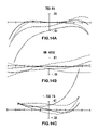
- FIGS. 14A–C show lateral aberration diagrams for the telephoto end according to numerical example 3.
- FIG. 15 is a layout drawing showing the configuration of a zoom lens of the second embodiment according to numerical examples 4 to 6;
- FIGS. 16A–E show longitudinal aberration diagrams for the wide angle end according to numerical example 4.
- FIGS. 17A–E show longitudinal aberration diagrams for the standard position according to numerical example 4.
- FIGS. 18A–E show longitudinal aberration diagrams for the telephoto end according to numerical example 4.
- FIGS. 19A–C show lateral aberration diagrams for the telephoto end according to numerical example 4.
- FIGS. 20A–E show longitudinal aberration diagrams for the wide angle end according to numerical example 5;
- FIGS. 21A–E show longitudinal aberration diagrams for the standard position according to numerical example 5;
- FIGS. 22A–E show longitudinal aberration diagrams for the telephoto end according to numerical example 5;
- FIGS. 23A–C show lateral aberration diagrams for the telephoto end according to numerical example 5;
- FIGS. 24A–E show longitudinal aberration diagrams for the wide angle end according to numerical example 6;
- FIGS. 25A–E show longitudinal aberration diagrams for the standard position according to numerical example 6;
- FIGS. 26A–E show longitudinal aberration diagrams for the telephoto end according to numerical example 6;
- FIGS. 27A–C show lateral aberration diagrams for the telephoto end according to numerical example 6;
- FIG. 28 is a layout drawing showing the configuration of a video camera according to a third embodiment.
- FIG. 29 is a layout drawing showing the configuration of a digital still camera according to a fourth embodiment.
- FIG. 1 shows the basic configuration of a zoom lens of first and second embodiment, having blurred image compensation.
- the zoom lens as disclosed herein is a four-group zoom lens made up of a first lens group having a positive optical power, a second lens group a negative optical power, a third lens group a positive optical power and a fourth lens group a positive optical power, arranged in that order from an object side to an image plane side.
- a magnification action is performed by moving the second lens group and the fourth lens group in a direction parallel to the optical axis
- focus adjustment is performed by moving the fourth lens group in a direction parallel to the optical axis.
- the third lens group is moved in a direction perpendicular to the optical axis so as to compensate for the fluctuation of the image when camera shake occurs (blurred image).
- the zoom lens of the first embodiment and the second embodiment while the first and third lens groups are fixed with respect to the image plane, the second and fourth lens groups are moved in a direction parallel to the optical axis during zooming ation. Moreover, the fourth lens group is moved in a direction parallel to the optical axis during focus adjustment. Furthermore, the third lens group is moved in a direction perpendicular to the optical axis in order to compensate for the blurred image.
- FIG. 2 is a layout drawing showing the configuration of a zoom lens of the first embodiment.
- the lens group denoted by r 1 to r 5 is the first lens group
- the lens group denoted by r 6 to r 12 is the second lens group
- the lens group denoted by r 14 to r 18 is the third lens group
- the lens group denoted by r 19 to r 22 is the fourth lens group.
- the optical components denoted by r 23 and r 24 in FIG. 2 are an optical low-pass filter and a flat plate that is equivalent to the faceplate of a CCD.
- the first lens group have, sequentially from the object side to the image plane side, a negative meniscus lens element convex to the object side, a positive lens element having a biconvex shape and a positive meniscus lens element convex to the object side.
- the first lens element counting from the object side is cemented the second lens element counting from the object side together.
- the second lent group have, sequentially from the object side to the image plane side, a negative meniscus lens element convex to the object side, a negative meniscus lens element concave to the object side, a positive lens element having a biconvex shape and a negative lens element having a biconcave shape.
- the third lens element counting from the object side is cemented the fourth lens element counting from the object side together.
- the third lens group have, sequentially from the object side to the image plane side, a positive lens element having a biconvex shape, a positive lens element having a biconvex shape and a negative lens element having a biconcave shape.
- the second lens element counting from the object side is cemented the third lens element counting from the object side together.
- the fourth lens group have, sequentially from the object side to the image plane side, a positive lens element having a biconvex shape, a negative lens element having a biconcave shape and a positive lens element having a biconvex shape. All of lens groups are cemented each other.
- FIG. 15 is a layout drawing showing the configuration of a zoom lens of the second embodiment.
- the third lens group comparing with the first embodiment, has only difference in which the most object side lens element in the third lens group is a positive meniscus lens element convex to the object side.
- CL is an effective lens diameter of the ata least one aspherical surface
- dsagi is an amount of asphericity at the effective lens diameter.
- h denotes the height from the optical axis
- SAG denotes the distance (sag amount) from the apex of the aspherical surface to the point on the aspherical surface where the height from the optical axis is h
- R denotes the radius of curvature at the apex of the aspherical surface
- K denotes the conic constant
- D, E, F, G, H, I and J denote the aspheric surface coefficients.
- conditional expression (1) is defined to attain good aberration properties even when processing errors occur.
- the value of the conditional expression (1) is falls below the lower limit, the performance tends not to deteriorate even when processing errors occur on the aspherical surface.
- the effect of introducing an aspherical surface is difficult to be achieved, thus making it difficult to correct aberration sufficiently.
- the value of the conditional expression (1) exceeds the upper limit, although it is possible to correct aberration favorably, the performance deterioration becomes significant in the occurrence of processing errors.
- conditional expression (1)′ is satisfied. 0.006 ⁇
- the zoom lens of the embodiments it is desirable for the zoom lens of the embodiments to satisfy the range defined by the following conditional expressions (2) to (4). 0.035 ⁇ dP g,F12 ⁇ 0.070 (2) 0.045 ⁇ dP g,d12 ⁇ 0.080 (3) ⁇ 0.040 ⁇ dP C,A′12 ⁇ 0.020 (4)
- dP g,F12 is a constant of anomalous dispersion of the second lens element of the first lens group, counted from the object side, with respect to partial dispersion ratio for the g-line (435 nm) and F-line (486 nm),
- dP g,d12 is a constant of anomalous dispersion of the second lens element of the first lens group, counted from the object side, with respect to partial dispersion ratio for the g-line (435 nm) and d-line (587 nm), and
- dP C,A′12 is a constant of anomalous dispersion of the second lens element of the first lens group, counted from the object side, with respect to partial dispersion ratio for the C-line (656 nm) and A′-line (768 nm).
- the straight line linking the two points representing these two glass types on a diagram in which the partial dispersion ratio is plotted on the vertical axis and the Abbe number is plotted on the horizontal axis is taken as the standard line.
- the difference between the partial dispersion ratio of the glass type used for each lens and the partial dispersion ratio corresponding to the Abbe number of the glass type on the standard line is expressed as dP x,y .
- conditional expressions (2) to (4) are conditions that are necessary to correct chromatic aberration at the shorter wavelength side and the longer wavelength side simultaneously.
- a material with a large anomalous dispersion is required.
- the conditional expressions (2) to (4) represent the anomalous dispersion properties from the shorter wavelengths to the longer wavelengths.
- the zoom lens of the embodiments it is desirable for the zoom lens of the embodiments to satisfy the range defined by the following conditional expressions (5) to (7). ⁇ 0.040 ⁇ dP g,F11 ⁇ dP g,F12 ⁇ 0.020 (5) ⁇ 0.055 ⁇ dP g,d11 ⁇ dP g,d12 ⁇ 0.025 (6) 0.018 ⁇ dP C,A′11 ⁇ dP C,A′12 ⁇ 0.036 (7)
- dP g,F11 is a constant of anomalous dispersion of the first lens element of the first lens group, counted from the object side, with respect to partial dispersion ratio for the g-line (435 nm) and F-line (486 nm),
- dP g,d11 is a constant of anomalous dispersion of the first lens element of the first lens group, counted from the object side, with respect to partial dispersion ratio for the g-line (435 nm) and d-line (587 nm),
- dP C,A′ is a constant of anomalous dispersion of the first lens element of the first lens group, counted from the object side, with respect to partial dispersion ratio for the C-line (656 nm) and A′-line (768 nm),
- dP g,F12 is a constant of anomalous dispersion of the second lens element of the first lens group, counted from the object side, with respect to partial dispersion ratio for the g-line (435 nm) and F-line (486 nm),
- dP g,d12 is a constant of anomalous dispersion of the second lens element of the first lens group, counted from the object side, with respect to partial dispersion ratio for the g-line (435 nm) and d-line (587 nm), and
- dP C,A′12 is a constant of anomalous dispersion of the second lens element of the first lens group, counted from the object side, with respect to partial dispersion ratio for the C-line (656 nm) and A′-line (768 nm).
- conditional expressions (5) to (7) are conditions for a lens having a negative refractive power and a lens having a positive refractive power in the case of correcting the chromatic aberration at two or more different wavelengths.
- f 31 is a focal length of the first lens of the third lens group, counted from the object side, and
- f 32 is a focal length of the second lens of the third lens group, counted from the object side.
- the refractive powers of the first lens and the second lens of the third lens group, counted from the object side as the above-described conditional expression (8)
- the angles of deviation of rays of light incident on these lenses can be optimized, so that spherical aberration can be corrected favorably.
- the refractive power of the first lens of the third lens group, counted from the object side becomes too large, so that spherical aberration tends to occur in the direction of the object side.
- conditional expression (8)′ is satisfied. 0.80 ⁇ f 31 /f 32 ⁇ 0.95 (8)′
- the third lens group includes a meniscus convex lens element, a convex lens element and a concave lens element, arranged in that order from the object side to the image plane side, and the following conditional expression (9) is satisfied. 0.01 ⁇
- p 1 is a power of the object side surface of the meniscus convex lens
- p 2 is a power of the image plane side surface of the meniscus convex lens.
- conditional expression (9) falls below the lower limit, the refractive power of the object side surface becomes too small and the refractive power of the image plane side surface becomes too large, thus making it difficult to correct aberration favorably.
- value of the conditional expression (9) exceeds the upper limit, the curvature of the object side surface and that of the image plane side surface become similar to each other, resulting in a lens shape that is difficult to be processed.
- the image plane side surface is made concave, so that the lenses do not have to be fixed to the frame of a lens barrel at its spherical portions when they are fixed to the lens barrel. As a result, tilting and decentering of the lens will not occur. Furthermore, since the refractive power of the image plane side surface is small, the performance of a single lens is less deteriorated due to surface misalignment as compared to a biconvex lens.
- conditional expression (9)′ is satisfied. 0.015 ⁇
- the third lens group includes a meniscus convex lens element, a convex lens element and a concave lens element, arranged in that order from the object side to the image plane side, and the following conditional expressions (10) and (11) are satisfied.
- n d31 is a refractive index of the meniscus convex lens element, which is the first lens element of the third lens group, counted from the object side,
- ⁇ d31 is an Abbe number of the meniscus convex lens element, which is the first lens element of the third lens group, counted from the object side, and
- ⁇ d32 is an Abbe number of the convex lens element, which is the second lens element of the third lens group, counted from the object side.
- conditional expression (10) falls below the lower limit, the refractive power of the lens surface becomes too strong, so that spherical aberration and coma aberration tend to occur.
- value of the conditional expression (11) exceeds the upper limit, chromatic aberration will be overcorrected.
- RIH is an image height
- R is a radius of curvature of the concave surface of the fourth lens group that is located closest to the image side.
- conditional expression (12) In the case of cementing lenses together, it is necessary to fill an adhesive having a low refractive index between the lens surfaces to be cemented, resulting in a large refractive index difference between the adhesive and the lenses. This becomes a cause of ghosting or flare. It is undesirable that the value of the conditional expression (12) falls below the lower limit, since ghosting or flare resulting from the reflections at the image plane or between the cemented surface located closest to the image plane and a face plate, a low-pass filter or the like is generated in the vicinity of the center of the picture. When the value of the conditional expression (12) exceeds the upper limit, the refractive power of the cemented surface becomes too small, thus making it difficult to correct lateral chromatic aberration sufficiently. By satisfying the conditional expression (12), it is possible to correct lateral chromatic aberration favorably, while diverting ghosting or flare to the peripheral portion of the picture.
- conditional expression (12)′ is satisfied. 130 ⁇ R/RIH ⁇ 200 (12)′
- f 1 is a focal length of the first lens group
- f 2 is a focal length of the second lens group
- ⁇ 2w is a magnification of the second lens group at wide angle end
- ⁇ 2T is a magnification of the second lens group at telephoto angle end
- f T is a focal length of the entire zoom lens at telephoto end
- f W is a focal length of the entire zoom lens at wide angle end.
- ⁇ 2w is a magnification of the second lens group at wide angle end
- ⁇ 2T is a magnification of the second lens group at telephoto angle end
- f T is a focal length of the entire zoom lens at telephoto end
- f W is a focal length of the entire zoom lens at wide angle end.
- the lens group of the first and the second embodiments comprise only refractive type lens elements that deflect the incident ray by refraction
- the present invention is not limited thereto.
- the lens group may comprise diffractive type lens elements that deflect the incident ray by diffraction, refractive-diffractive hybrid lens elements that deflect the incident ray by a combination of diffraction and refraction, or the like.
- an optical pass of the zoom lens by providing a reflective surface on the optical pass.
- a bending position of the optical pass is adjustable.
- the optical low pass filter which has a flat plate shape is provided between the zoom lens and the imaging sensor, both a birefringent optical filter made of birefringence material such like quartz and diffractive optical filter having a diffraction can be adopted. Further, in the first or second embodiment, it is possible to delete the optical low pass filter based on the property of imaging sensor.
- FIG. 28 shows the configuration of a video camera according to a third embodiment.
- the video camera includes a zoom lens 281 , as well as a low-pass filter 282 and an imaging element 283 , arranged in that order on the image plane side of the zoom lens 281 .
- a viewfinder 285 is connected to the imaging element 283 through a signal processing circuit 284 .
- the zoom lens having a blurred image compensation function according to first embodiment above is used as the zoom lens 281 , thus realizing a high-performance video camera having a blurred image compensation function.
- a detector (sensor) 287 for detecting camera shake is connected to the third lens group of the zoom lens 281 through a drive (actuator) 286 for moving the third lens group in a direction perpendicular to the optical axis.
- zoom lens described in first embodiment above was used in the present embodiment, this zoom lens may be replaced by, for example, the zoom lenses described in second embodiment above.
- FIG. 29 shows the configuration of a digital still camera according to a fourth embodiment.
- the reference numeral 231 denotes the zoom lens having a blurred image compensation function according to first embodiment 1 above.
- the numeral 232 denotes a collapsing lens barrel, 233 denotes an optical viewfinder and 234 denotes a shutter.
- zoom lens described in first embodiment above was used in the present embodiment, this zoom lens may be replaced by, for example, the zoom lenses described in second embodiment above.
- r (mm) denotes the radius of curvature of the lens face
- d (mm) denotes the thickness of each lens or the air space between each pair of adjacent lenses
- n denotes the refractive index of each lens at the d-line
- ⁇ d denotes the Abbe number of each lens at the d-line.
- AS all of aspherical surfaces are defined by the above-mentioned formula (AS).
- optical performance is exhibited by longitudinal aberration diagrams, when the blurred image compensation function is not effective.
- optical performance is exhibited by lateral aberration diagrams, when the blurred image compensation function is effective.
- the longitudinal aberration diagrams from the left to the right, responds to spherical aberration diagram A, astigmatism diagram B, distortion diagram C, axial chromatic aberration diagram D and lateral chromatic aberration diagram E.
- spherical aberration diagram A and axial chromatic aberration diagram D, vertical axes express the F number.
- astigmatism diagram B, distortion diagram C and lateral chromatic aberration diagram E vertical axes express the half angle of view.
- a spherical aberration values at the d-line are indicated.
- the solid line indicates the sagittal curvature of field and the dashed line indicates the meridional curvature of field.
- the axial chromatic aberration diagram D the solid line indicates values at the d-line
- the short dashed line indicates values at the F-line
- the long dashed line indicates values at the C-line.
- the short dashed line indicates values at the F-line and the long dashed line indicates values at the C-line.
- A is a lateral aberration at a relative image height of 0.75
- B is a lateral aberration at the center of the picture
- C is a lateral aberration at a relative image height of ⁇ 0.75.
- the solid line indicates values at the d-line
- the short dashes line indicates values at the F-line
- the long dashed line indicates values at the C-line
- the dash-dotted line indicates values at the g-line.
- Numerical example 1 corresponds to first embodiment as shown in FIG. 2 .
- table 1 shows lens data
- table 2 shows the aspheric surface coefficients of the zoom lens.
- Table 3 shows the variable air space (mm) by zooming when the object point is located at infinity from the tip of the most object side lens.
- f (mm), F/No and 2 ⁇ (°) denote, respectively, the focal length, the F number and the angle of view at the wide angle end, the standard position and the telephoto end.
- FIGS. 3A to 5E show aberration diagrams for the wide angle end, the standard position and the telephoto end of the zoom lens according to the numerical example 1.
- the zoom lens of the present example has aberration correction properties sufficient to attain high resolution.
- the diagrams ( FIGS. 3A to 5E ) show little deviation which is, at least in part, illustrative of sufficient aberration correction properties.
- this and other factors illustrated by these diagrams are keenly understood by one of ordinary skill in the art.
- FIGS. 6A–C shows aberration diagrams for the telephoto end at the time of compensating for a blurred image caused by moving the zoom lens of 0.28°.
- the zoom lens of the present example exhibits favorable aberration properties even during zoom lens moving. Notably, aberration remains substantially within the same order of magnitude with and without camera shake.
- this and other factors illustrated by these diagrams are keenly understood by one of ordinary skill in the art.
- Numerical example 2 corresponds to first embodiment as shown in FIG. 2 .
- table 4 shows lens data
- table 5 shows the aspheric surface coefficients of the zoom lens.
- Table 6 shows the variable air space (mm) by zooming when the object point is located at infinity from the tip of the most object side lens.
- f (mm), F/No and 2 ⁇ (°) denote, respectively, the focal length, the F number and the angle of view at the wide angle end, the standard position and the telephoto end.
- FIGS. 7A to 9E show aberration diagrams for the wide angle end, the standard position and the telephoto end of the zoom lens according to the numerical example 2.
- the zoom lens of the present example has aberration correction properties sufficient to attain high resolution.
- the diagrams ( FIGS. 7A to 9E ) show little deviation which is, at least in part, illustrative of sufficient aberration correction properties.
- this and other factors illustrated by these diagrams are keenly understood by one of ordinary skill in the art.
- FIGS. 10A–C shows aberration diagrams for the telephoto end at the time of compensating for a blurred image caused by moving the zoom lens of 0.28°.
- the zoom lens of the present example exhibits favorable aberration properties even during zoom lens moving. Notably, aberration remains substantially within the same order of magnitude with and without camera shake.
- this and other factors illustrated by these diagrams are keenly understood by one of ordinary skill in the art.
- Numerical example 3 corresponds to first embodiment as shown in FIG. 2 .
- table 7 shows lens data
- table 8 shows the aspheric surface coefficients of the zoom lens.
- Table 9 shows the variable air space (mm) by zooming when the object point is located at infinity from the tip of the most object side lens.
- f (mm), F/No and 2 ⁇ (°) denote, respectively, the focal length, the F number and the angle of view at the wide angle end, the standard position and the telephoto end.
- FIGS. 11A to 13E show aberration diagrams for the wide angle end, the standard position and the telephoto end of the zoom lens according to the numerical example 3.
- the zoom lens of the present example has aberration correction properties sufficient to attain high resolution.
- the diagrams show little deviation which is, at least in part, illustrative of sufficient aberration correction properties.
- this and other factors illustrated by these diagrams are keenly understood by one of ordinary skill in the art.
- FIGS. 14A–C shows aberration diagrams for the telephoto end at the time of compensating for a blurred image caused by moving the zoom lens of 0.27°.
- the zoom lens of the present example exhibits favorable aberration properties even during zoom lens moving. Notably, aberration remains substantially within the same order of magnitude with and without camera shake.
- this and other factors illustrated by these diagrams are keenly understood by one of ordinary skill in the art.
- Numerical example 4 corresponds to second embodiment as shown in FIG. 15 .
- table 10 shows lens data
- table 11 shows the aspheric surface coefficients of the zoom lens.
- Table 12 shows the variable air space (mm) by zooming when the object point is located at infinity from the tip of the most object side lens.
- f (mm), F/No and 2 ⁇ (°) denote, respectively, the focal length, the F number and the angle of view at the wide angle end, the standard position and the telephoto end.
- FIGS. 16A to 18E show aberration diagrams for the wide angle end, the standard position and the telephoto end of the zoom lens according to the numerical example 4.
- the zoom lens of the present example has aberration correction properties sufficient to attain high resolution.
- the diagrams show little deviation which is, at least in part, illustrative of sufficient aberration correction properties.
- this and other factors illustrated by these diagrams are keenly understood by one of ordinary skill in the art.
- FIGS. 19A–C shows aberration diagrams for the telephoto end at the time of compensating for a blurred image caused by moving the zoom lens of 0.35°.
- the zoom lens of the present example exhibits favorable aberration properties even during zoom lens moving. Notably, aberration remains substantially within the same order of magnitude with and without camera shake.
- this and other factors illustrated by these diagrams are keenly understood by one of ordinary skill in the art.
- Numerical example 5 corresponds to second embodiment as shown in FIG. 15 .
- table 13 shows lens data
- table 14 shows the aspheric surface coefficients of the zoom lens.
- Table 15 shows the variable air space (mm) by zooming when the object point is located at infinity from the tip of the most object side lens.
- f (mm), F/No and 2 ⁇ (°) denote, respectively, the focal length, the F number and the angle of view at the wide angle end, the standard position and the telephoto end.
- FIGS. 20A to 22E show aberration diagrams for the wide angle end, the standard position and the telephoto end of the zoom lens according to the numerical example 5.
- the zoom lens of the present example has aberration correction properties sufficient to attain high resolution.
- the diagrams show little deviation which is, at least in part, illustrative of sufficient aberration correction properties.
- this and other factors illustrated by these diagrams are keenly understood by one of ordinary skill in the art.
- FIGS. 23A–C shows aberration diagrams for the telephoto end at the time of compensating for a blurred image caused by moving the zoom lens of 0.31°.
- the zoom lens of the present example exhibits favorable aberration properties even during zoom lens moving. Notably, aberration remains substantiallywithin the same order of magnitude with and without camera shake.
- this and other factors illustrated by these diagrams are keenly understood by one of ordinary skill in the art.
- Numerical example 6 corresponds to second embodiment as shown in FIG. 15 .
- table 16 shows lens data
- table 17 shows the aspheric surface coefficients of the zoom lens.
- Table 18 shows the variable air space (mm) by zooming when the object point is located at infinity from the tip of the most object side lens.
- f (mm), F/No and 2 ⁇ (°) denote, respectively, the focal length, the F number and the angle of view at the wide angle end, the standard position and the telephoto end.
- FIGS. 24A to 26E show aberration diagrams for the wide angle end, the standard position and the telephoto end of the zoom lens according to the numerical example 6.
- the zoom lens of the present example has aberration correction properties sufficient to attain high resolution.
- the diagrams show little deviation which is, at least in part, illustrative of sufficient aberration correction properties.
- this and other factors illustrated by these diagrams are keenly understood by one of ordinary skill in the art.
- FIGS. 27A–C shows aberration diagrams for the telephoto end at the time of compensating for a blurred image caused by moving the zoom lens of 0.30°.
- the zoom lens of the present example exhibits favorable aberration properties even during zoom lens moving. Notably, aberration remains substantially within the same order of magnitude with and without camera shake.
- this and other factors illustrated by these diagrams are keenly understood by one of ordinary skill in the art.
Landscapes
- Physics & Mathematics (AREA)
- General Physics & Mathematics (AREA)
- Optics & Photonics (AREA)
- Lenses (AREA)
- Studio Devices (AREA)
Applications Claiming Priority (2)
| Application Number | Priority Date | Filing Date | Title |
|---|---|---|---|
| JP2003-362580 | 2003-10-22 | ||
| JP2003362580A JP2005128186A (ja) | 2003-10-22 | 2003-10-22 | ズームレンズ、並びにそれを用いたビデオカメラ及びデジタルスチルカメラ |
Publications (2)
| Publication Number | Publication Date |
|---|---|
| US20050088756A1 US20050088756A1 (en) | 2005-04-28 |
| US7139130B2 true US7139130B2 (en) | 2006-11-21 |
Family
ID=34509992
Family Applications (1)
| Application Number | Title | Priority Date | Filing Date |
|---|---|---|---|
| US10/968,024 Expired - Fee Related US7139130B2 (en) | 2003-10-22 | 2004-10-20 | Zoom lens, and optical apparatus using the same |
Country Status (4)
| Country | Link |
|---|---|
| US (1) | US7139130B2 (zh) |
| JP (1) | JP2005128186A (zh) |
| CN (1) | CN100386661C (zh) |
| WO (1) | WO2005040889A1 (zh) |
Cited By (7)
| Publication number | Priority date | Publication date | Assignee | Title |
|---|---|---|---|---|
| US20060215278A1 (en) * | 2005-03-24 | 2006-09-28 | Fujinon Corporation | Zoom optical sysem that includes a function of preventing blurring of an image |
| US20070201146A1 (en) * | 2006-02-27 | 2007-08-30 | Canon Kabushiki Kaisha | Zoom lens and image pickup apparatus having the same |
| US20080297901A1 (en) * | 2007-05-29 | 2008-12-04 | Nikon Corporation | Zoom lens system, optical apparatus, and method for forming an image |
| US20090046366A1 (en) * | 2007-08-13 | 2009-02-19 | Nikon Corporation | Zoom lens, and optical apparatus and method for forming an image of an object using the zoom lens |
| DE102007051620A1 (de) * | 2007-10-26 | 2009-04-30 | Jos. Schneider Optische Werke Gmbh | Makro-Objektiv |
| US20110134529A1 (en) * | 2007-03-09 | 2011-06-09 | Nikon Corporation | Zoom lens, optical apparatus, and method for forming an image of an object |
| US8681433B2 (en) | 2011-03-10 | 2014-03-25 | Fujifilm Corporation | Variable magnification optical system and imaging apparatus |
Families Citing this family (24)
| Publication number | Priority date | Publication date | Assignee | Title |
|---|---|---|---|---|
| JP2005164840A (ja) * | 2003-12-01 | 2005-06-23 | Canon Inc | 光学系及びその設計方法 |
| KR100671544B1 (ko) * | 2005-06-10 | 2007-01-19 | 삼성전자주식회사 | 줌렌즈 광학계 |
| JP4863046B2 (ja) * | 2005-08-23 | 2012-01-25 | ソニー株式会社 | ズームレンズ及び撮像装置 |
| JP4919330B2 (ja) * | 2005-10-31 | 2012-04-18 | 富士フイルム株式会社 | ズームレンズ |
| CN100429549C (zh) * | 2005-10-31 | 2008-10-29 | 富士能株式会社 | 变倍透镜 |
| US7593040B2 (en) * | 2006-01-30 | 2009-09-22 | Omnivision Technologies, Inc. | Image anti-shake in digital cameras |
| JP2007212846A (ja) | 2006-02-10 | 2007-08-23 | Sony Corp | ズームレンズ及び撮像装置 |
| JP4591780B2 (ja) | 2006-02-13 | 2010-12-01 | ソニー株式会社 | 可変焦点距離レンズ系及び撮像装置 |
| US7515352B2 (en) * | 2006-02-17 | 2009-04-07 | Nikon Corporation | Zoom lens system and optical device using thereof |
| JP4264581B2 (ja) | 2006-04-25 | 2009-05-20 | ソニー株式会社 | 可変焦点距離レンズ系及び撮像装置 |
| WO2007129677A1 (ja) * | 2006-05-01 | 2007-11-15 | Nikon Corporation | ズームレンズとこれを具備する光学装置 |
| ATE443275T1 (de) * | 2006-07-20 | 2009-10-15 | Nikon Corp | Vibrationsbeständiges telezoomobjektiv mit vier linsengruppen |
| JP2009169264A (ja) * | 2008-01-18 | 2009-07-30 | Sony Corp | ズームレンズ及び撮像装置 |
| JP2009223295A (ja) * | 2008-02-20 | 2009-10-01 | Olympus Imaging Corp | ズームレンズ及びそれを用いた撮像装置 |
| JP5505758B2 (ja) * | 2008-04-11 | 2014-05-28 | 株式会社ニコン | 撮影レンズ、この撮影レンズを備えた光学機器 |
| JP5540512B2 (ja) * | 2009-01-30 | 2014-07-02 | 株式会社ニコン | 変倍光学系、及び、この変倍光学系を有する光学機器 |
| JP5703869B2 (ja) * | 2011-03-15 | 2015-04-22 | ソニー株式会社 | ズームレンズ及び撮像装置 |
| CN104395808B (zh) * | 2012-07-05 | 2017-09-29 | 富士胶片株式会社 | 摄像透镜及摄像装置 |
| JP6219183B2 (ja) * | 2014-01-30 | 2017-10-25 | 富士フイルム株式会社 | 撮像レンズおよび撮像装置 |
| CN103823294B (zh) * | 2014-02-24 | 2016-06-08 | 湖北久之洋红外系统股份有限公司 | 具有超长焦距的连续变焦中波红外光学系统 |
| CN105319672B (zh) * | 2014-05-26 | 2019-07-12 | 奥林巴斯株式会社 | 广角镜头及具有该广角镜头的摄像装置 |
| KR102375648B1 (ko) * | 2014-12-17 | 2022-03-17 | 엘지이노텍 주식회사 | 촬상 렌즈, 이를 포함하는 카메라 모듈 및 디지털 기기 |
| JP7140571B2 (ja) * | 2018-07-04 | 2022-09-21 | キヤノン株式会社 | 光学系および撮像装置 |
| CN115202014B (zh) * | 2022-06-02 | 2023-11-03 | 昆明物理研究所 | 紧凑非制冷长波红外连续变焦光学系统 |
Citations (25)
| Publication number | Priority date | Publication date | Assignee | Title |
|---|---|---|---|---|
| US3736048A (en) * | 1971-06-11 | 1973-05-29 | Rank Organisation Ltd | Optical objectives of variable equivalent focal length |
| JPH07128619A (ja) | 1993-11-04 | 1995-05-19 | Canon Inc | 防振機能を有した変倍光学系 |
| JPH0829737A (ja) | 1994-07-12 | 1996-02-02 | Sony Corp | 像ブレ補正変倍光学系 |
| JPH08160299A (ja) | 1994-12-12 | 1996-06-21 | Olympus Optical Co Ltd | ズームレンズ |
| JPH08160300A (ja) | 1994-12-12 | 1996-06-21 | Olympus Optical Co Ltd | ズームレンズ |
| US5719708A (en) | 1994-12-12 | 1998-02-17 | Olympus Optical Co., Ltd. | Zoom lens system |
| JPH10260356A (ja) | 1997-03-18 | 1998-09-29 | Canon Inc | 防振機能を有した変倍光学系 |
| JPH11237551A (ja) | 1997-12-18 | 1999-08-31 | Matsushita Electric Ind Co Ltd | ズームレンズ及びそれを用いたビデオカメラ |
| JP2000227552A (ja) | 1999-02-08 | 2000-08-15 | Sony Corp | ズームレンズ |
| WO2001027677A1 (fr) | 1999-10-14 | 2001-04-19 | Matsushita Electric Industrial Co., Ltd. | Objectif zoom et camera video le comprenant |
| JP2001116996A (ja) | 1999-10-15 | 2001-04-27 | Matsushita Electric Ind Co Ltd | ズームレンズ及びそれを用いたビデオカメラ |
| JP2001117004A (ja) | 1999-10-14 | 2001-04-27 | Matsushita Electric Ind Co Ltd | ズームレンズ及びそれを用いたビデオカメラ |
| JP2001221948A (ja) | 2000-02-10 | 2001-08-17 | Matsushita Electric Ind Co Ltd | ズームレンズ |
| JP2002107622A (ja) | 2000-09-26 | 2002-04-10 | Canon Inc | 変倍レンズ系およびそれを用いた光学機器 |
| US6404561B1 (en) | 1999-10-29 | 2002-06-11 | Minolta Co., Ltd. | Taking lens apparatus |
| US6414800B1 (en) | 1999-05-10 | 2002-07-02 | Canon Kabushiki Kaisha | Variable magnification optical system and camera having the same |
| JP2002287028A (ja) | 2001-03-26 | 2002-10-03 | Matsushita Electric Ind Co Ltd | ズームレンズ |
| US6473231B2 (en) | 1997-03-18 | 2002-10-29 | Canon Kabushiki Kaisha | Variable magnification optical system having image stabilizing function |
| JP2002365540A (ja) | 2001-06-05 | 2002-12-18 | Matsushita Electric Ind Co Ltd | 手振れ補正機能搭載ズームレンズと手振れ補正機能搭載ビデオカメラ及び光学機器と光学装置 |
| JP2003098434A (ja) | 2001-09-25 | 2003-04-03 | Canon Inc | ズームレンズ及びそれを有する光学機器 |
| US6606202B2 (en) * | 2000-09-26 | 2003-08-12 | Canon Kabushiki Kaisha | Zoom lens system and optical apparatus using the same |
| JP2003295057A (ja) | 2002-04-04 | 2003-10-15 | Canon Inc | ズームレンズ及びそれを有する光学機器 |
| US6751029B2 (en) * | 2002-03-29 | 2004-06-15 | Canon Kabushiki Kaisha | Zoom lens image pickup apparatus |
| US6999240B2 (en) * | 2001-11-28 | 2006-02-14 | Matsushita Electric Industrial Co., Ltd. | Zoom lens and video camera using it |
| US6999241B2 (en) * | 2002-02-25 | 2006-02-14 | Matsushita Electric Industrial Co., Ltd. | Zoom lens, and video camera and digital still camera using the zoom lens |
-
2003
- 2003-10-22 JP JP2003362580A patent/JP2005128186A/ja active Pending
-
2004
- 2004-10-19 WO PCT/JP2004/015445 patent/WO2005040889A1/ja active Application Filing
- 2004-10-19 CN CNB2004800259114A patent/CN100386661C/zh not_active Expired - Fee Related
- 2004-10-20 US US10/968,024 patent/US7139130B2/en not_active Expired - Fee Related
Patent Citations (26)
| Publication number | Priority date | Publication date | Assignee | Title |
|---|---|---|---|---|
| US3736048A (en) * | 1971-06-11 | 1973-05-29 | Rank Organisation Ltd | Optical objectives of variable equivalent focal length |
| JPH07128619A (ja) | 1993-11-04 | 1995-05-19 | Canon Inc | 防振機能を有した変倍光学系 |
| JPH0829737A (ja) | 1994-07-12 | 1996-02-02 | Sony Corp | 像ブレ補正変倍光学系 |
| JPH08160300A (ja) | 1994-12-12 | 1996-06-21 | Olympus Optical Co Ltd | ズームレンズ |
| US5719708A (en) | 1994-12-12 | 1998-02-17 | Olympus Optical Co., Ltd. | Zoom lens system |
| JPH08160299A (ja) | 1994-12-12 | 1996-06-21 | Olympus Optical Co Ltd | ズームレンズ |
| US6473231B2 (en) | 1997-03-18 | 2002-10-29 | Canon Kabushiki Kaisha | Variable magnification optical system having image stabilizing function |
| JPH10260356A (ja) | 1997-03-18 | 1998-09-29 | Canon Inc | 防振機能を有した変倍光学系 |
| US6606194B2 (en) * | 1997-03-18 | 2003-08-12 | Canon Kabushiki Kaisha | Variable magnification optical system having image stabilizing function |
| JPH11237551A (ja) | 1997-12-18 | 1999-08-31 | Matsushita Electric Ind Co Ltd | ズームレンズ及びそれを用いたビデオカメラ |
| JP2000227552A (ja) | 1999-02-08 | 2000-08-15 | Sony Corp | ズームレンズ |
| US6414800B1 (en) | 1999-05-10 | 2002-07-02 | Canon Kabushiki Kaisha | Variable magnification optical system and camera having the same |
| WO2001027677A1 (fr) | 1999-10-14 | 2001-04-19 | Matsushita Electric Industrial Co., Ltd. | Objectif zoom et camera video le comprenant |
| JP2001117004A (ja) | 1999-10-14 | 2001-04-27 | Matsushita Electric Ind Co Ltd | ズームレンズ及びそれを用いたビデオカメラ |
| JP2001116996A (ja) | 1999-10-15 | 2001-04-27 | Matsushita Electric Ind Co Ltd | ズームレンズ及びそれを用いたビデオカメラ |
| US6404561B1 (en) | 1999-10-29 | 2002-06-11 | Minolta Co., Ltd. | Taking lens apparatus |
| JP2001221948A (ja) | 2000-02-10 | 2001-08-17 | Matsushita Electric Ind Co Ltd | ズームレンズ |
| JP2002107622A (ja) | 2000-09-26 | 2002-04-10 | Canon Inc | 変倍レンズ系およびそれを用いた光学機器 |
| US6606202B2 (en) * | 2000-09-26 | 2003-08-12 | Canon Kabushiki Kaisha | Zoom lens system and optical apparatus using the same |
| JP2002287028A (ja) | 2001-03-26 | 2002-10-03 | Matsushita Electric Ind Co Ltd | ズームレンズ |
| JP2002365540A (ja) | 2001-06-05 | 2002-12-18 | Matsushita Electric Ind Co Ltd | 手振れ補正機能搭載ズームレンズと手振れ補正機能搭載ビデオカメラ及び光学機器と光学装置 |
| JP2003098434A (ja) | 2001-09-25 | 2003-04-03 | Canon Inc | ズームレンズ及びそれを有する光学機器 |
| US6999240B2 (en) * | 2001-11-28 | 2006-02-14 | Matsushita Electric Industrial Co., Ltd. | Zoom lens and video camera using it |
| US6999241B2 (en) * | 2002-02-25 | 2006-02-14 | Matsushita Electric Industrial Co., Ltd. | Zoom lens, and video camera and digital still camera using the zoom lens |
| US6751029B2 (en) * | 2002-03-29 | 2004-06-15 | Canon Kabushiki Kaisha | Zoom lens image pickup apparatus |
| JP2003295057A (ja) | 2002-04-04 | 2003-10-15 | Canon Inc | ズームレンズ及びそれを有する光学機器 |
Cited By (15)
| Publication number | Priority date | Publication date | Assignee | Title |
|---|---|---|---|---|
| US7212350B2 (en) * | 2005-03-24 | 2007-05-01 | Fujinon Corporation | Zoom optical system that includes a function of preventing blurring of an image |
| US20060215278A1 (en) * | 2005-03-24 | 2006-09-28 | Fujinon Corporation | Zoom optical sysem that includes a function of preventing blurring of an image |
| US20070201146A1 (en) * | 2006-02-27 | 2007-08-30 | Canon Kabushiki Kaisha | Zoom lens and image pickup apparatus having the same |
| US7315424B2 (en) * | 2006-02-27 | 2008-01-01 | Canon Kabushiki Kaisha | Zoom lens and image pickup apparatus having the same |
| US20110134529A1 (en) * | 2007-03-09 | 2011-06-09 | Nikon Corporation | Zoom lens, optical apparatus, and method for forming an image of an object |
| US8437088B2 (en) | 2007-03-09 | 2013-05-07 | Nikon Corporation | Zoom lens, optical apparatus, and method for forming an image of an object |
| US20080297901A1 (en) * | 2007-05-29 | 2008-12-04 | Nikon Corporation | Zoom lens system, optical apparatus, and method for forming an image |
| US8498051B2 (en) | 2007-05-29 | 2013-07-30 | Nikon Corporation | Zoom lens system, optical apparatus, and method for forming an image |
| US20090046366A1 (en) * | 2007-08-13 | 2009-02-19 | Nikon Corporation | Zoom lens, and optical apparatus and method for forming an image of an object using the zoom lens |
| US8411361B2 (en) | 2007-08-13 | 2013-04-02 | Nikon Corporation | Zoom lens, and optical apparatus and method for forming an image of an object using the zoom lens |
| DE102007051620A1 (de) * | 2007-10-26 | 2009-04-30 | Jos. Schneider Optische Werke Gmbh | Makro-Objektiv |
| US7791825B2 (en) | 2007-10-26 | 2010-09-07 | Jos. Schneider Optische Werke Gmbh | Macro objective |
| DE102007051620B4 (de) * | 2007-10-26 | 2010-01-21 | Jos. Schneider Optische Werke Gmbh | Makro-Objektiv |
| US20090135499A1 (en) * | 2007-10-26 | 2009-05-28 | Jos. Schneider Optische Werke Gmbh | Macro objective |
| US8681433B2 (en) | 2011-03-10 | 2014-03-25 | Fujifilm Corporation | Variable magnification optical system and imaging apparatus |
Also Published As
| Publication number | Publication date |
|---|---|
| WO2005040889A1 (ja) | 2005-05-06 |
| JP2005128186A (ja) | 2005-05-19 |
| CN100386661C (zh) | 2008-05-07 |
| US20050088756A1 (en) | 2005-04-28 |
| CN1849545A (zh) | 2006-10-18 |
Similar Documents
| Publication | Publication Date | Title |
|---|---|---|
| US7139130B2 (en) | Zoom lens, and optical apparatus using the same | |
| US8908283B2 (en) | Optical system, imaging apparatus, and method for forming image by the optical system | |
| US8320051B2 (en) | Zoom lens system, imaging device and camera | |
| US8681433B2 (en) | Variable magnification optical system and imaging apparatus | |
| US7777974B2 (en) | Macro lens, optical apparatus, and method for manufacturing the macro lens | |
| US8134783B2 (en) | Zoom lens system and image pickup apparatus including the zoom lens system | |
| JP4944436B2 (ja) | ズームレンズ及びそれを有する撮像装置 | |
| US7492526B2 (en) | High zoom ratio zoom lens, optical apparatus using the same, and method for varying focal length | |
| US10095012B2 (en) | Zoom lens system, optical apparatus and method for manufacturing zoom lens system | |
| US8199415B2 (en) | Zoom lens system, optical device with zoom lens system, and method of manufacturing zoom lens system | |
| US20120300113A1 (en) | Zoom lens and image pickup apparatus equipped with zoom lens | |
| US7457047B2 (en) | Zoom optical system and imaging apparatus using the same | |
| US8503101B2 (en) | Zoom lens and image pickup apparatus equipped with zoom lens | |
| US10101568B2 (en) | Zoom lens, optical device, and method for manufacturing the zoom lens | |
| US8248703B2 (en) | Zoom lens and optical apparatus having the zoom lens | |
| US7940472B2 (en) | Zoom lens and optical apparatus equipped therewith | |
| US7589905B2 (en) | Optical system and optical apparatus including the same | |
| US8351128B2 (en) | Zoom lens and image pickup apparatus using the same | |
| US20170068076A1 (en) | Zoom optical system, imaging device and method for manufacturing the zoom optical system | |
| JP2010122536A (ja) | ズームレンズ | |
| US8040615B2 (en) | Zoom lens and optical apparatus equipped therewith | |
| US20230023567A1 (en) | Optical system, optical apparatus and method for manufacturing the optical system | |
| US20230408799A1 (en) | Zoom lens, image pickup apparatus having the same, and imaging system | |
| US20230258914A1 (en) | Optical system, optical apparatus and method for manufacturing the optical system | |
| US20230236383A1 (en) | Optical system, optical apparatus and method for manufacturing the optical system |
Legal Events
| Date | Code | Title | Description |
|---|---|---|---|
| AS | Assignment |
Owner name: MATSUSHITA ELECTRIC INDUSTRIAL CO., LTD., JAPAN Free format text: ASSIGNMENT OF ASSIGNORS INTEREST;ASSIGNOR:YAMADA, KATSU;REEL/FRAME:015915/0535 Effective date: 20041015 |
|
| FEPP | Fee payment procedure |
Free format text: PAYOR NUMBER ASSIGNED (ORIGINAL EVENT CODE: ASPN); ENTITY STATUS OF PATENT OWNER: LARGE ENTITY |
|
| FPAY | Fee payment |
Year of fee payment: 4 |
|
| REMI | Maintenance fee reminder mailed | ||
| LAPS | Lapse for failure to pay maintenance fees | ||
| STCH | Information on status: patent discontinuation |
Free format text: PATENT EXPIRED DUE TO NONPAYMENT OF MAINTENANCE FEES UNDER 37 CFR 1.362 |
|
| FP | Lapsed due to failure to pay maintenance fee |
Effective date: 20141121 |