US7118317B2 - Fastener - Google Patents
Fastener Download PDFInfo
- Publication number
- US7118317B2 US7118317B2 US10/332,477 US33247703A US7118317B2 US 7118317 B2 US7118317 B2 US 7118317B2 US 33247703 A US33247703 A US 33247703A US 7118317 B2 US7118317 B2 US 7118317B2
- Authority
- US
- United States
- Prior art keywords
- curvature
- component
- circular sections
- centers
- contact
- Prior art date
- Legal status (The legal status is an assumption and is not a legal conclusion. Google has not performed a legal analysis and makes no representation as to the accuracy of the status listed.)
- Expired - Lifetime, expires
Links
Images

Classifications
-
- F—MECHANICAL ENGINEERING; LIGHTING; HEATING; WEAPONS; BLASTING
- F16—ENGINEERING ELEMENTS AND UNITS; GENERAL MEASURES FOR PRODUCING AND MAINTAINING EFFECTIVE FUNCTIONING OF MACHINES OR INSTALLATIONS; THERMAL INSULATION IN GENERAL
- F16B—DEVICES FOR FASTENING OR SECURING CONSTRUCTIONAL ELEMENTS OR MACHINE PARTS TOGETHER, e.g. NAILS, BOLTS, CIRCLIPS, CLAMPS, CLIPS OR WEDGES; JOINTS OR JOINTING
- F16B35/00—Screw-bolts; Stay-bolts; Screw-threaded studs; Screws; Set screws
- F16B35/04—Screw-bolts; Stay-bolts; Screw-threaded studs; Screws; Set screws with specially-shaped head or shaft in order to fix the bolt on or in an object
- F16B35/06—Specially-shaped heads
-
- B—PERFORMING OPERATIONS; TRANSPORTING
- B60—VEHICLES IN GENERAL
- B60B—VEHICLE WHEELS; CASTORS; AXLES FOR WHEELS OR CASTORS; INCREASING WHEEL ADHESION
- B60B3/00—Disc wheels, i.e. wheels with load-supporting disc body
- B60B3/14—Attaching disc body to hub ; Wheel adapters
- B60B3/16—Attaching disc body to hub ; Wheel adapters by bolts or the like
Definitions
- the present invention generally relates to connecting elements used, for example, for the attachment of automobile wheels or rims to a motor vehicle by means of wheel bolts. More specifically, the present invention relates to a method for implementing fastener arrangements or screw elements to avoid deformation and damage of the outer and inner surfaces of such connecting elements.
- the solutions embodying the principles of the present invention are based on the recognition that the unfavorable forced contact conditions in the region of the front or rear edge, in the direction in which the screw is screwed in, of the concavely curved inner surface of the component, result from the fact that the centers of curvature of the curvature of the outer surface and the curvature of the inner surface are not spaced apart from each other in a direction vertical to the longitudinal axis.
- a method of connecting elements embodying the principles of this invention is by creating a fastener arrangement, where the contact surfaces in an axial section of the fastener device are defined by arcuate sections curved in such a way, that the center(s) of curvature of the convexly curved outer surface extending in a direction perpendicular to the longitudinal axis is (are) located at such a distance from the center(s) of curvature of the concavely curved inner surface, that the contact surfaces, when they are fastened to each other, are located between the ends of their arc sections.
- a screw element according to the principles of this invention, where the contact surfaces are defined, in an axial section of the screw element, by curved arc sections, the centers of curvature of which are located at such a distance from the longitudinal axis that the convexly curved outer surface and the concavely curved inner surface of the component, when they are fastened to each other, are in contact with each other between the ends of their arcuate sections.
- the present invention concerns a fastener arrangement consisting of a component and a screw element with an area for the application of force for a turning tool, where the component and the screw element, when fastened to each other, are in contact with each other by way of contact surfaces, and where the contact surface of the screw element on the side facing the component, has a convexly curved outer surface, and where the contact surface of the component has a concavely curved inner surface, while the outer surface and the inner surface are positioned coaxially with respect to a common longitudinal axis, which runs through the component and the screw element.
- the invention concerns also a screw element with an area for the application of force for a turning tool and a contact surface shaped as a convexly curved outer surface for contact with a concavely curved inner surface of a component, which contact surface points in the direction in which the screw element is screwed in, where the outer surface of the screw element and the inner surface of the component are positioned coaxially with respect to a longitudinal axis running through the component and the screw element.
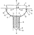
- FIG. 1 is a cross-sectional view revealing the axial section of one embodiment of the fastener arrangement embodying the principles of the present invention.
- FIG. 2 is a cross-sectional view revealing the axial section of another embodiment of the fastener arrangement embodying the principles of the present invention.
- the fastener arrangement or the screw element therefore, permits a fastening operation, even for multiple use, with a defined torque.
- the overall load is reduced to such an extent that the diameter, which determines the friction moment, experiences only minor dimensional changes, so that ultimately only small changes in the desired tensioning forces occur.
- FIGS. 1 and 2 show, in an axial section through the longitudinal axis X—X, a screw element 1 in accordance with the invention, for example a screw, which can be screwed into a component 2 in the direction of thread engagement E.
- the screw element 1 shows a screw head 4 and threaded shaft 6 adjacent to it, with a screw point 8 located at its free end.
- the screw head 4 consists of a force application area 10 and a contact surface 11 , which is turned toward the component 2 , which contact surface is formed as a convexly curved outer surface 12 , which curves around at least one center of curvature A.
- the area of force application 10 can, for example, be in the form of a hexagon, an interior hexagon, a slot, a cross recessed head, or the like.
- the component 2 has an opening 14 for the threaded shaft 6 and a contact surface 11 for receiving the convexly curved outer surface 12 .
- the contact surface 11 is configured as an inner surface 16 , which is concavely curved around at least one center of curvature B.
- the convexly curved outer surface 12 and the concavely curved inner surface 16 are coaxial with respect to a longitudinal axis X—X.
- the outer surface 12 of the screw is convexly curved in such a manner that its centers of curvature A 1 , A 2 are, in contrast to the center of curvature B of the inner surface 16 , not located on the longitudinal axis X—X.
- FIG. 2 a second embodiment in accordance with the invention is shown in an axial section, where the inner surface 16 of component 2 is concavely curved in such a manner, that its centers of curvature B 1 , B 2 are, in contrast to the center of curvature A of the outer surface 12 , not located on the longitudinal axis X—X.
- This arrangement as well guarantees that the contact occurs not at the edge regions of the inner surface 16 or at the ends of the concave or convex arc sections.
- the invention is not limited to the examples of the embodiment shown and described, but also includes all embodiments acting in an equivalent manner within the spirit of the invention; for example, a nut, which is threaded onto threaded shaft 6 , can also serve as a screw element, which is located in a concavely curved inner surface 16 .
- a combination of the embodiments shown in FIGS. 1 and 2 is conceivable, where the arc section of the concavely curved inner surface 16 as well as the arc sections of the outer surface 12 are each curved in the axial section around two centers A 1 , A 2 ; B 1 , 82 .
- the arc sections cannot only be defined as circular sections, but also, for example, as elliptical sections.
- the invention is thus far also not limited to the combination of characteristics defined in claim 1 , but it can also be defined by any possible combination of certain characteristics of all disclosed individual characteristics.
Landscapes
- Engineering & Computer Science (AREA)
- General Engineering & Computer Science (AREA)
- Mechanical Engineering (AREA)
- Connection Of Plates (AREA)
- Transmission Devices (AREA)
- Surgical Instruments (AREA)
- Dowels (AREA)
- Piezo-Electric Or Mechanical Vibrators, Or Delay Or Filter Circuits (AREA)
- Crystals, And After-Treatments Of Crystals (AREA)
- Mutual Connection Of Rods And Tubes (AREA)
- Mechanical Coupling Of Light Guides (AREA)
Priority Applications (1)
| Application Number | Priority Date | Filing Date | Title |
|---|---|---|---|
| US11/514,120 US7399150B2 (en) | 2000-07-13 | 2006-08-31 | Connecting element |
Applications Claiming Priority (3)
| Application Number | Priority Date | Filing Date | Title |
|---|---|---|---|
| DE20012107.3 | 2000-07-13 | ||
| DE20012107U DE20012107U1 (de) | 2000-07-13 | 2000-07-13 | Verbindungselement |
| PCT/EP2001/007338 WO2002006685A1 (de) | 2000-07-13 | 2001-06-27 | Verbindungselement |
Related Child Applications (1)
| Application Number | Title | Priority Date | Filing Date |
|---|---|---|---|
| US11/514,120 Continuation US7399150B2 (en) | 2000-07-13 | 2006-08-31 | Connecting element |
Publications (2)
| Publication Number | Publication Date |
|---|---|
| US20040101382A1 US20040101382A1 (en) | 2004-05-27 |
| US7118317B2 true US7118317B2 (en) | 2006-10-10 |
Family
ID=7943864
Family Applications (2)
| Application Number | Title | Priority Date | Filing Date |
|---|---|---|---|
| US10/332,477 Expired - Lifetime US7118317B2 (en) | 2000-07-13 | 2001-06-27 | Fastener |
| US11/514,120 Expired - Lifetime US7399150B2 (en) | 2000-07-13 | 2006-08-31 | Connecting element |
Family Applications After (1)
| Application Number | Title | Priority Date | Filing Date |
|---|---|---|---|
| US11/514,120 Expired - Lifetime US7399150B2 (en) | 2000-07-13 | 2006-08-31 | Connecting element |
Country Status (9)
| Country | Link |
|---|---|
| US (2) | US7118317B2 (de) |
| EP (1) | EP1299652B1 (de) |
| JP (1) | JP2004504551A (de) |
| AT (1) | ATE292759T1 (de) |
| AU (1) | AU2001281908A1 (de) |
| DE (2) | DE20012107U1 (de) |
| ES (1) | ES2236283T3 (de) |
| PL (1) | PL365636A1 (de) |
| WO (1) | WO2002006685A1 (de) |
Cited By (24)
| Publication number | Priority date | Publication date | Assignee | Title |
|---|---|---|---|---|
| US20080129048A1 (en) * | 2006-12-01 | 2008-06-05 | Victaulic Company | Coupling with concave bearing surface |
| US20090208308A1 (en) * | 2004-01-21 | 2009-08-20 | Nippon Telegraph And Telephone Corporation | Screw Driving Device and Screw |
| US20110131898A1 (en) * | 2010-04-29 | 2011-06-09 | Jacob Johannes Nies | Flange connection |
| US8282136B2 (en) | 2008-06-30 | 2012-10-09 | Mueller International, Llc | Slip on groove coupling with multiple sealing gasket |
| USD680629S1 (en) | 2011-11-21 | 2013-04-23 | Mueller International, Llc | Slip-on coupling segment |
| USD680630S1 (en) | 2011-11-21 | 2013-04-23 | Mueller International, Llc | Slip-on coupling assembly |
| US20130302190A1 (en) * | 2012-05-11 | 2013-11-14 | Sanyo Denki Co., Ltd. | Fan frame |
| USD696751S1 (en) | 2011-10-27 | 2013-12-31 | Mueller International, Llc | Slip-on gasket |
| US9039046B2 (en) | 2012-01-20 | 2015-05-26 | Mueller International, Llc | Coupling with tongue and groove |
| US9168585B2 (en) | 2012-11-02 | 2015-10-27 | Mueller International, Llc | Coupling with extending parting line |
| US9194516B2 (en) | 2012-01-20 | 2015-11-24 | Mueller International, Llc | Slip-on coupling |
| US9500307B2 (en) | 2012-01-20 | 2016-11-22 | Mueller International, Llc | Slip-on coupling gasket |
| US9534715B2 (en) | 2012-01-20 | 2017-01-03 | Mueller International, Llc | Coupling gasket with multiple sealing surfaces |
| US9581183B2 (en) | 2015-02-17 | 2017-02-28 | The Hillman Group, Inc. | Screw-type fastener |
| US10436238B2 (en) | 2016-04-04 | 2019-10-08 | The Hillman Group, Inc. | Screw type fastener |
| US20190338475A1 (en) * | 2015-08-31 | 2019-11-07 | Vsl International Ag | Cable anchorage system |
| US10982703B2 (en) | 2018-04-09 | 2021-04-20 | The Hillman Group, Inc. | Screw-type fastener for concrete and hurricane resistance applications |
| US11085481B2 (en) * | 2016-07-12 | 2021-08-10 | Fairchild Fasteners Europe - Camloc Gmbh | Insert and method for connecting an electrical connection to a wall |
| US11105361B2 (en) | 2017-11-03 | 2021-08-31 | The Hillman Group, Inc. | Screw-type fastener |
| US11867218B2 (en) | 2019-05-20 | 2024-01-09 | Andreas Stihl Ag & Co. Kg | Work apparatus and stud bolt for a work apparatus |
| US12473942B2 (en) | 2021-03-30 | 2025-11-18 | The Hillman Group, Inc. | Wood screw |
| USD1106810S1 (en) | 2022-09-29 | 2025-12-23 | The Hillman Group, Inc. | Screw |
| USD1115507S1 (en) | 2023-06-02 | 2026-03-03 | The Hillman Group, Inc. | Screw |
| USD1116789S1 (en) | 2023-06-02 | 2026-03-10 | The Hillman Group, Inc. | Screw |
Families Citing this family (14)
| Publication number | Priority date | Publication date | Assignee | Title |
|---|---|---|---|---|
| DE10361863A1 (de) * | 2003-12-30 | 2005-07-28 | Robert Bosch Gmbh | Vorrichtung zur Befestigung eines Wälzlagers |
| DE102007003487A1 (de) * | 2007-01-24 | 2008-07-31 | Schaeffler Kg | Furchschraube, Schraubverbindung und Spannvorrichtung für einen Zugmitteltrieb einer Brennkraftmaschine |
| US8061236B2 (en) * | 2007-09-20 | 2011-11-22 | Bear Corporation | Bicycle pedal |
| DE102008027136A1 (de) * | 2008-05-30 | 2009-12-10 | Dr. Ing. H.C. F. Porsche Aktiengesellschaft | Kugelkalotte |
| US8486116B2 (en) * | 2010-01-08 | 2013-07-16 | Biomet Manufacturing Ring Corporation | Variable angle locking screw |
| US8728129B2 (en) | 2011-01-07 | 2014-05-20 | Biomet Manufacturing, Llc | Variable angled locking screw |
| KR101145774B1 (ko) * | 2011-10-14 | 2012-05-16 | 와토스코리아 주식회사 | 지지리브에 압축력이 발생하는 지지부재의 체결구조 |
| US8790059B2 (en) * | 2012-03-27 | 2014-07-29 | The Johns Hopkins University | Washer assembly for mounting on irregular surfaces |
| JP2017096486A (ja) * | 2015-11-24 | 2017-06-01 | 株式会社メイドー | 球面座ボルト |
| US20180081452A1 (en) * | 2016-09-19 | 2018-03-22 | Hyundai Motor Company | Touch input apparatus and vehicle including the same |
| IT201900004049A1 (it) * | 2019-03-20 | 2020-09-20 | Brugola Oeb Ind S P A | Mezzo di fissaggio. |
| CN112061233A (zh) * | 2019-06-10 | 2020-12-11 | 广州汽车集团股份有限公司 | 一种转向节螺栓孔 |
| USD956544S1 (en) * | 2020-11-06 | 2022-07-05 | Wheel Pros, Llc | Bolt |
| DE102024205874A1 (de) * | 2024-06-25 | 2026-01-08 | Volkswagen Aktiengesellschaft | Anordnung zum Befestigen eines Fahrzeugteils an einem Fahrzeug, Befestigungselement, Fahrzeugteil und Fahrzeug |
Citations (13)
| Publication number | Priority date | Publication date | Assignee | Title |
|---|---|---|---|---|
| US1264569A (en) * | 1915-11-16 | 1918-04-30 | Flannery Bolt Co | Flexible stay-bolt connection for boilers. |
| US1354610A (en) * | 1919-07-02 | 1920-10-05 | Flannery Bolt Co | Staybolt structure |
| US1447068A (en) * | 1922-04-08 | 1923-02-27 | Flannery Bolt Co | Stay-bolt structure for boilers |
| US1507841A (en) * | 1921-01-11 | 1924-09-09 | Flannery Bolt Co | Stay-bolt structure |
| US3135154A (en) * | 1961-04-26 | 1964-06-02 | Zenzic John | Locking and tension indicating washer nut device |
| US3313197A (en) * | 1965-09-08 | 1967-04-11 | Illinois Tool Works | Screw |
| US3429581A (en) * | 1964-05-15 | 1969-02-25 | Fritz Drexler | Sealing connection |
| US4127037A (en) * | 1976-11-08 | 1978-11-28 | Umc Electronics Company | Adjusting mechanism |
| DE3027191A1 (de) | 1980-07-18 | 1982-02-11 | Volkswagenwerk Ag, 3180 Wolfsburg | Schreibenrad fuer kraftfahrzeuge |
| US4717299A (en) | 1986-02-27 | 1988-01-05 | Armstong Fastenings, Ltd. | Wheel nut assemblies |
| US5143410A (en) * | 1990-06-30 | 1992-09-01 | Usui Kokusai Sangyo Kaisha Ltd. | Branch connectors for high-pressure branched fuel pipe |
| US5405227A (en) | 1992-06-17 | 1995-04-11 | Societe Nationale Industrielle Et Aerospatiale | Fasteners made of composite material of a ceramic matrix reinforced with refractory fibers |
| US5534032A (en) * | 1993-06-21 | 1996-07-09 | Zimmer, Inc. | Orthopaedic implant assembly |
Family Cites Families (3)
| Publication number | Priority date | Publication date | Assignee | Title |
|---|---|---|---|---|
| JPS5836559B2 (ja) * | 1975-12-22 | 1983-08-10 | ソニー株式会社 | 4 チヤンネルステレオサイセイソウチ |
| JPH1150960A (ja) * | 1997-08-01 | 1999-02-23 | Ntn Corp | 斜板式コンプレッサ用シュー及びその組込み構造 |
| JPH11182522A (ja) * | 1997-12-22 | 1999-07-06 | Sannohashi:Kk | ボルト及びボルトの締結構造 |
-
2000
- 2000-07-13 DE DE20012107U patent/DE20012107U1/de not_active Expired - Lifetime
-
2001
- 2001-06-27 US US10/332,477 patent/US7118317B2/en not_active Expired - Lifetime
- 2001-06-27 AU AU2001281908A patent/AU2001281908A1/en not_active Abandoned
- 2001-06-27 WO PCT/EP2001/007338 patent/WO2002006685A1/de not_active Ceased
- 2001-06-27 AT AT01960405T patent/ATE292759T1/de not_active IP Right Cessation
- 2001-06-27 EP EP01960405A patent/EP1299652B1/de not_active Expired - Lifetime
- 2001-06-27 JP JP2002512555A patent/JP2004504551A/ja active Pending
- 2001-06-27 PL PL01365636A patent/PL365636A1/xx not_active IP Right Cessation
- 2001-06-27 ES ES01960405T patent/ES2236283T3/es not_active Expired - Lifetime
- 2001-06-27 DE DE50105841T patent/DE50105841D1/de not_active Expired - Lifetime
-
2006
- 2006-08-31 US US11/514,120 patent/US7399150B2/en not_active Expired - Lifetime
Patent Citations (13)
| Publication number | Priority date | Publication date | Assignee | Title |
|---|---|---|---|---|
| US1264569A (en) * | 1915-11-16 | 1918-04-30 | Flannery Bolt Co | Flexible stay-bolt connection for boilers. |
| US1354610A (en) * | 1919-07-02 | 1920-10-05 | Flannery Bolt Co | Staybolt structure |
| US1507841A (en) * | 1921-01-11 | 1924-09-09 | Flannery Bolt Co | Stay-bolt structure |
| US1447068A (en) * | 1922-04-08 | 1923-02-27 | Flannery Bolt Co | Stay-bolt structure for boilers |
| US3135154A (en) * | 1961-04-26 | 1964-06-02 | Zenzic John | Locking and tension indicating washer nut device |
| US3429581A (en) * | 1964-05-15 | 1969-02-25 | Fritz Drexler | Sealing connection |
| US3313197A (en) * | 1965-09-08 | 1967-04-11 | Illinois Tool Works | Screw |
| US4127037A (en) * | 1976-11-08 | 1978-11-28 | Umc Electronics Company | Adjusting mechanism |
| DE3027191A1 (de) | 1980-07-18 | 1982-02-11 | Volkswagenwerk Ag, 3180 Wolfsburg | Schreibenrad fuer kraftfahrzeuge |
| US4717299A (en) | 1986-02-27 | 1988-01-05 | Armstong Fastenings, Ltd. | Wheel nut assemblies |
| US5143410A (en) * | 1990-06-30 | 1992-09-01 | Usui Kokusai Sangyo Kaisha Ltd. | Branch connectors for high-pressure branched fuel pipe |
| US5405227A (en) | 1992-06-17 | 1995-04-11 | Societe Nationale Industrielle Et Aerospatiale | Fasteners made of composite material of a ceramic matrix reinforced with refractory fibers |
| US5534032A (en) * | 1993-06-21 | 1996-07-09 | Zimmer, Inc. | Orthopaedic implant assembly |
Cited By (45)
| Publication number | Priority date | Publication date | Assignee | Title |
|---|---|---|---|---|
| US20090208308A1 (en) * | 2004-01-21 | 2009-08-20 | Nippon Telegraph And Telephone Corporation | Screw Driving Device and Screw |
| US7798757B2 (en) * | 2004-01-21 | 2010-09-21 | Nippon Telegraph And Telephone Corporation | Screw driving device and screw |
| US7800283B2 (en) | 2004-01-21 | 2010-09-21 | Nippon Telegraph And Telephone Corporation | Screw driving device and screw |
| US20080129048A1 (en) * | 2006-12-01 | 2008-06-05 | Victaulic Company | Coupling with concave bearing surface |
| US7789434B2 (en) * | 2006-12-01 | 2010-09-07 | Victaulic Company | Coupling with concave bearing surface |
| US8282136B2 (en) | 2008-06-30 | 2012-10-09 | Mueller International, Llc | Slip on groove coupling with multiple sealing gasket |
| US10047885B2 (en) | 2008-06-30 | 2018-08-14 | Anvil International, Llc | Slip on groove coupling with multiple sealing gasket |
| US9297482B2 (en) | 2008-06-30 | 2016-03-29 | Mueller International, Llc | Slip on groove coupling with multiple sealing gasket |
| US10036493B2 (en) | 2008-06-30 | 2018-07-31 | Anvil International, Llc | Slip on groove coupling with multiple sealing gasket |
| US8550502B2 (en) | 2008-06-30 | 2013-10-08 | Mueller International, Llc | Slip on groove coupling with multiple sealing gasket |
| US8615865B2 (en) | 2008-06-30 | 2013-12-31 | Mueller International, Llc | Slip on groove coupling with multiple sealing gasket |
| US9239123B2 (en) | 2008-06-30 | 2016-01-19 | Mueller International, Llc | Slip on groove coupling with multiple sealing gasket |
| US20110131898A1 (en) * | 2010-04-29 | 2011-06-09 | Jacob Johannes Nies | Flange connection |
| USD696751S1 (en) | 2011-10-27 | 2013-12-31 | Mueller International, Llc | Slip-on gasket |
| USD680630S1 (en) | 2011-11-21 | 2013-04-23 | Mueller International, Llc | Slip-on coupling assembly |
| USD680629S1 (en) | 2011-11-21 | 2013-04-23 | Mueller International, Llc | Slip-on coupling segment |
| US10641421B2 (en) | 2012-01-20 | 2020-05-05 | Anvil International, Llc | Coupling gasket with multiple sealing surfaces |
| US9631746B2 (en) | 2012-01-20 | 2017-04-25 | Anvil International, Llc | Coupling with tongue and groove |
| US9297484B2 (en) | 2012-01-20 | 2016-03-29 | Mueller International, Llc | Slip-on coupling |
| US9500307B2 (en) | 2012-01-20 | 2016-11-22 | Mueller International, Llc | Slip-on coupling gasket |
| US9534715B2 (en) | 2012-01-20 | 2017-01-03 | Mueller International, Llc | Coupling gasket with multiple sealing surfaces |
| US11739869B2 (en) | 2012-01-20 | 2023-08-29 | ASC Engineered Solutions, LLC | Coupling gasket with multiple sealing surfaces |
| US10288200B2 (en) | 2012-01-20 | 2019-05-14 | Anvil International, Llc | Coupling with tongue and groove |
| US10385997B2 (en) | 2012-01-20 | 2019-08-20 | Anvil International, Llc | Slip-on coupling gasket |
| US9194516B2 (en) | 2012-01-20 | 2015-11-24 | Mueller International, Llc | Slip-on coupling |
| US9039046B2 (en) | 2012-01-20 | 2015-05-26 | Mueller International, Llc | Coupling with tongue and groove |
| US11365835B2 (en) | 2012-01-20 | 2022-06-21 | ASC Engineered Solutions, LLC | Coupling gasket with multiple sealing surfaces |
| US10274115B2 (en) | 2012-01-20 | 2019-04-30 | Anvil International, Llc | Coupling with tongue and groove |
| US20130302190A1 (en) * | 2012-05-11 | 2013-11-14 | Sanyo Denki Co., Ltd. | Fan frame |
| US9581174B2 (en) * | 2012-05-11 | 2017-02-28 | Sanyo Denki Co., Ltd. | Fan frame |
| US9168585B2 (en) | 2012-11-02 | 2015-10-27 | Mueller International, Llc | Coupling with extending parting line |
| US10207320B2 (en) | 2012-11-02 | 2019-02-19 | Anvil International, Llc | Coupling with extending parting line |
| US10247219B2 (en) | 2015-02-17 | 2019-04-02 | The Hillman Group, Inc. | Screw-type fastener |
| US9581183B2 (en) | 2015-02-17 | 2017-02-28 | The Hillman Group, Inc. | Screw-type fastener |
| US20190338475A1 (en) * | 2015-08-31 | 2019-11-07 | Vsl International Ag | Cable anchorage system |
| US10920383B2 (en) * | 2015-08-31 | 2021-02-16 | Vsl International Ag | Cable anchorage system |
| US10436238B2 (en) | 2016-04-04 | 2019-10-08 | The Hillman Group, Inc. | Screw type fastener |
| US11085481B2 (en) * | 2016-07-12 | 2021-08-10 | Fairchild Fasteners Europe - Camloc Gmbh | Insert and method for connecting an electrical connection to a wall |
| US11105361B2 (en) | 2017-11-03 | 2021-08-31 | The Hillman Group, Inc. | Screw-type fastener |
| US10982703B2 (en) | 2018-04-09 | 2021-04-20 | The Hillman Group, Inc. | Screw-type fastener for concrete and hurricane resistance applications |
| US11867218B2 (en) | 2019-05-20 | 2024-01-09 | Andreas Stihl Ag & Co. Kg | Work apparatus and stud bolt for a work apparatus |
| US12473942B2 (en) | 2021-03-30 | 2025-11-18 | The Hillman Group, Inc. | Wood screw |
| USD1106810S1 (en) | 2022-09-29 | 2025-12-23 | The Hillman Group, Inc. | Screw |
| USD1115507S1 (en) | 2023-06-02 | 2026-03-03 | The Hillman Group, Inc. | Screw |
| USD1116789S1 (en) | 2023-06-02 | 2026-03-10 | The Hillman Group, Inc. | Screw |
Also Published As
| Publication number | Publication date |
|---|---|
| WO2002006685A1 (de) | 2002-01-24 |
| ATE292759T1 (de) | 2005-04-15 |
| JP2004504551A (ja) | 2004-02-12 |
| EP1299652B1 (de) | 2005-04-06 |
| AU2001281908A1 (en) | 2002-01-30 |
| PL365636A1 (en) | 2005-01-10 |
| DE50105841D1 (de) | 2005-05-12 |
| US20060291980A1 (en) | 2006-12-28 |
| US7399150B2 (en) | 2008-07-15 |
| ES2236283T3 (es) | 2005-07-16 |
| DE20012107U1 (de) | 2001-11-29 |
| US20040101382A1 (en) | 2004-05-27 |
| EP1299652A1 (de) | 2003-04-09 |
Similar Documents
| Publication | Publication Date | Title |
|---|---|---|
| US7118317B2 (en) | Fastener | |
| US6517301B2 (en) | Fastener assembly including a screw element and a supporting element | |
| US4717299A (en) | Wheel nut assemblies | |
| US6537007B1 (en) | Fastening structure including a bolt having a serration that is press-fit into a bolthole of a flange | |
| JP3781057B2 (ja) | リベッティング可能な要素、組立体、組立方法及びリベッティングダイ | |
| US5324149A (en) | Lightweight lug nut | |
| US8931990B2 (en) | Pierce nut and use thereof | |
| EP4074993A1 (de) | Drehstopp- und loslösungsstoppdichtung, befestigungsverbindungsmechanismus und befestigungsverfahren | |
| US5823065A (en) | Driving crank for a windshield wiper system | |
| JP3813985B2 (ja) | 自動車車輪ホイールディスク及びその製造方法 | |
| EP0823564B1 (de) | Selbstsichernde Mutter | |
| US20080296965A1 (en) | Wheel Hub Comprising Axial Recesses Formed Between the Holes for Wheel Nuts | |
| US6767069B2 (en) | Bicycle wheel rim having corner reinforcing members at junctions of a spoke mounting wall with tire retaining walls of a rim body | |
| US7862128B2 (en) | Vehicle wheel spoke connection | |
| US6478521B1 (en) | Washer element for a wheel bolt and/or wheel nut of a motor vehicle wheel | |
| US6257677B1 (en) | Bicycle wheel rim | |
| US7097402B2 (en) | Lock nut | |
| JP2006321480A (ja) | 自転車の車輪用スポークおよび車輪 | |
| EP4096933B1 (de) | Fahrzeugräder und verfahren zur herstellung von fahrzeugrädern | |
| US6129384A (en) | Bolt-on part, especially a bumper of a motor vehicle | |
| JP2777116B2 (ja) | 自動車用のタイロッド | |
| JP5270897B2 (ja) | 回転体と回転軸の締結構造 | |
| KR102152530B1 (ko) | 차량용 액슬 허브 씰링캡 | |
| CN215284248U (zh) | 控制臂组件、悬架系统及汽车 | |
| US12097907B2 (en) | Steering device |
Legal Events
| Date | Code | Title | Description |
|---|---|---|---|
| AS | Assignment |
Owner name: ALTENLOH, BRINCK & CO GMBH & CO. KG, GERMANY Free format text: ASSIGNMENT OF ASSIGNORS INTEREST;ASSIGNOR:HOFSCHNEIDER, MANFRED;REEL/FRAME:014212/0407 Effective date: 20030508 |
|
| STCF | Information on status: patent grant |
Free format text: PATENTED CASE |
|
| FPAY | Fee payment |
Year of fee payment: 4 |
|
| FPAY | Fee payment |
Year of fee payment: 8 |
|
| MAFP | Maintenance fee payment |
Free format text: PAYMENT OF MAINTENANCE FEE, 12TH YEAR, LARGE ENTITY (ORIGINAL EVENT CODE: M1553) Year of fee payment: 12 |
|
| AS | Assignment |
Owner name: ABC UMFORMTECHNIK GMBH & CO. KG, GERMANY Free format text: ASSIGNMENT OF ASSIGNORS INTEREST;ASSIGNOR:ALTENLOH, BRINCK & CO. GMBH & CO. KG;REEL/FRAME:052474/0548 Effective date: 20191202 |