US7113368B2 - Recording and reproducing apparatus for preventing erroneous erasure - Google Patents
Recording and reproducing apparatus for preventing erroneous erasure Download PDFInfo
- Publication number
- US7113368B2 US7113368B2 US10/511,667 US51166705A US7113368B2 US 7113368 B2 US7113368 B2 US 7113368B2 US 51166705 A US51166705 A US 51166705A US 7113368 B2 US7113368 B2 US 7113368B2
- Authority
- US
- United States
- Prior art keywords
- erroneous erasure
- erasure prevention
- cassette
- existing
- format
- Prior art date
- Legal status (The legal status is an assumption and is not a legal conclusion. Google has not performed a legal analysis and makes no representation as to the accuracy of the status listed.)
- Expired - Fee Related
Links
Images


Classifications
-
- G—PHYSICS
- G11—INFORMATION STORAGE
- G11B—INFORMATION STORAGE BASED ON RELATIVE MOVEMENT BETWEEN RECORD CARRIER AND TRANSDUCER
- G11B23/00—Record carriers not specific to the method of recording or reproducing; Accessories, e.g. containers, specially adapted for co-operation with the recording or reproducing apparatus ; Intermediate mediums; Apparatus or processes specially adapted for their manufacture
- G11B23/28—Indicating or preventing prior or unauthorised use, e.g. cassettes with sealing or locking means, write-protect devices for discs
- G11B23/287—Indicating or preventing prior or unauthorised use, e.g. cassettes with sealing or locking means, write-protect devices for discs by mechanical lock
-
- G—PHYSICS
- G11—INFORMATION STORAGE
- G11B—INFORMATION STORAGE BASED ON RELATIVE MOVEMENT BETWEEN RECORD CARRIER AND TRANSDUCER
- G11B23/00—Record carriers not specific to the method of recording or reproducing; Accessories, e.g. containers, specially adapted for co-operation with the recording or reproducing apparatus ; Intermediate mediums; Apparatus or processes specially adapted for their manufacture
- G11B23/28—Indicating or preventing prior or unauthorised use, e.g. cassettes with sealing or locking means, write-protect devices for discs
-
- G—PHYSICS
- G11—INFORMATION STORAGE
- G11B—INFORMATION STORAGE BASED ON RELATIVE MOVEMENT BETWEEN RECORD CARRIER AND TRANSDUCER
- G11B15/00—Driving, starting or stopping record carriers of filamentary or web form; Driving both such record carriers and heads; Guiding such record carriers or containers therefor; Control thereof; Control of operating function
- G11B15/02—Control of operating function, e.g. switching from recording to reproducing
- G11B15/05—Control of operating function, e.g. switching from recording to reproducing by sensing features present on or derived from record carrier or container
- G11B15/06—Control of operating function, e.g. switching from recording to reproducing by sensing features present on or derived from record carrier or container by sensing auxiliary features on record carriers or containers, e.g. to stop machine near the end of a tape
- G11B15/07—Control of operating function, e.g. switching from recording to reproducing by sensing features present on or derived from record carrier or container by sensing auxiliary features on record carriers or containers, e.g. to stop machine near the end of a tape on containers
-
- G—PHYSICS
- G11—INFORMATION STORAGE
- G11B—INFORMATION STORAGE BASED ON RELATIVE MOVEMENT BETWEEN RECORD CARRIER AND TRANSDUCER
- G11B15/00—Driving, starting or stopping record carriers of filamentary or web form; Driving both such record carriers and heads; Guiding such record carriers or containers therefor; Control thereof; Control of operating function
- G11B15/675—Guiding containers, e.g. loading, ejecting cassettes
- G11B15/6751—Guiding containers, e.g. loading, ejecting cassettes with movement of the cassette parallel to its main side, i.e. front loading
-
- G—PHYSICS
- G11—INFORMATION STORAGE
- G11B—INFORMATION STORAGE BASED ON RELATIVE MOVEMENT BETWEEN RECORD CARRIER AND TRANSDUCER
- G11B15/00—Driving, starting or stopping record carriers of filamentary or web form; Driving both such record carriers and heads; Guiding such record carriers or containers therefor; Control thereof; Control of operating function
- G11B15/675—Guiding containers, e.g. loading, ejecting cassettes
- G11B15/67544—Guiding containers, e.g. loading, ejecting cassettes with movement of the cassette parallel to its main side and subsequent movement perpendicular thereto, i.e. front loading
Definitions
- the present invention relates to a recording and reproducing apparatus capable of performing recording on and/or reproduction from an existing format cassette and a new format cassette and to a recording medium cassette used in the recording and reproducing apparatus.
- a hole referred to so-called an ID hole is provided in a casing of a video tape cassette and the like.
- the hole is used to prevent erroneous erasure of data recorded on a magnetic tape or to identify a recorded format, a material of a magnetic substance of a tape and the like.
- an erroneous erasure prevention member 103 capable of sliding in the longitudinal direction on the side surface 100 a is provided at a position adjacent to a corner inside a casing of a cassette 100 formed by combining top and bottom shells (not shown in the figures) and an erroneous erasure prevention hole 101 functioning as the ID hole provided on the bottom surface of the cassette casing is opened and closed by moving the erroneous erasure prevention member 103 .
- An example of the erroneous erasure prevention member 103 has such a structure as a stepped shape formed of a plurality of bending portions as shown in FIG. 2 , for example, and includes a lug portion 103 a used for the moving operation, a half-disc shaped protruding portion 103 b which opens and closes the erroneous erasure prevention hole 101 and an identification display portion 103 c to recognize visually through an display window 102 opened in the side surface 100 a of the cassette casing.
- the erroneous erasure prevention member 103 is moved by laying a finger or the like on the lug portion 103 a projecting from the inside of the display window 102 on the side surface 10 a of the cassette casing so that the display portion 103 c becomes visible in the whole display window 102 .
- the protruding portion 103 b of the erroneous erasure prevention member 103 closes the erroneous erasure prevention hole 101 to become a closed state.
- a position of the erroneous erasure prevention member 103 at this time is the position where the cassette is in a recordable state (REC position).
- the erroneous erasure prevention member 103 is moved by laying a nail on the lug portion 103 a projecting from the inside of the display window 102 in the side surface 100 a of the cassette casing so that the display portion 103 c disappears from the display window 102 and a recording prohibition display panel 102 a disposed behind becomes visible.
- the protruding portion 103 b of the erroneous erasure prevention member 103 which has closed the erroneous erasure prevention hole 101 , moves so that the erroneous erasure prevention hole 101 becomes an open state.
- a position of the erroneous erasure prevention member 103 at this time is the position where the cassette is in an non-recordable state (SAVE position).
- a detection hole is made to be the closed state at the recordable position and the detection hole is made to be the open state at the non-recordable position; that is, in a casing of a VHS video cassette or the like, for example, a nail has conventionally been provided for this hole when it is in a state of a blank cassette having nothing recorded yet and after recording, the nail is removed so that an existing record can not be deleted thereafter by erroneously making a duplicated recording; and hereupon this nail is made to be a movable one using the above described erroneous erasure prevention member, so that a state of nail-broken or nail-unbroken can be changed according to a necessity.
- a mechanical switch is conventionally used in order to detect the state of nail-broken or nail-unbroken
- a photo-sensor or the like for the detection by irradiating light from below, and also it can be considered to have a construction in which the detection hole is made to be a through hole which pierces from the top surface to the bottom surface of the cassette and light is applied from one side of the through hole to be sensed on the other side thereof.
- a high band 8 mm video has an erroneous erasure prevention detecting switch of a cassette.
- FIG. 3A schematically shows an erroneous erasure prevention hole and an erroneous erasure prevention detecting switch of a high band 8 mm video tape cassette.
- the erroneous erasure prevention of the cassette is identified using an erroneous erasure prevention detecting switch 107 , and the erroneous erasure prevention hole 101 becomes an open or closed state depending on a position of the erroneous erasure prevention member 103 which is visible from the display window 102 , and thereby, it is judged whether the cassette is in a recordable state or in a non-recordable state.
- a detection hole not shown in the figure is provided for identifying either a normal 8 mm video tape cassette or a high band 8 mm video tape cassette, so that it is judged whether it is a normal one or a high band one.
- a new product model is made to be capable of loading a new (higher) format only, or otherwise, it is necessary to have a complicated mechanism of higher/existing format compatible.
- the erroneous erasure prevention hole 101 of an existing format supporting cassette is continuously kept in the open state and the erroneous erasure prevention detecting switch 107 of the existing format is turned off to prevent the erroneous erasure with the existing format.
- a higher/existing format identification switch 122 When a higher cassette 110 is loaded into a VTR 120 , a higher/existing format identification switch 122 is engaged with a higher/existing format identification hole 112 to be turned off as shown in FIG. 4A . Then, it is judged that the cassette is the higher cassette, and also, a higher format erroneous erasure prevention detecting switch 123 is turned on by an erroneous erasure prevention member 115 to become a recordable state.
- the higher format erroneous erasure prevention detecting switch 123 is turned off to become a non-recordable state as shown in FIG. 4B .
- the higher/existing format identification switch 122 is depressed by the cassette casing to be turned on as shown in FIG. 5A . Then, it is identified that the cassette is the existing cassette, and also, an existing erroneous erasure prevention detecting switch 131 is turned on by an erroneous erasure prevention member 133 to become a recordable state.
- the existing erroneous erasure prevention detecting switch 131 is turned off to become a non-recordable state as shown in FIG. 5B .
- the present invention aims to propose a recording and reproducing apparatus and a recording medium cassette which are capable of performing recording on and reproduction from an existing format and a new format cassettes by implementing a simple design change to utilize an existing cassette and an existing drive unit.
- a first aspect of the present invention is a recording and reproducing apparatus that performs recording on and reproduction from both an existing format cassette having an existing erroneous erasure prevention means for preventing the erroneous erasure of data recorded with the existing format and a new format cassette having a first erroneous erasure prevention means at a position corresponding to a position of the existing erroneous erasure prevention means and also having a second erroneous erasure prevention means for preventing the erroneous erasure of data recorded with the new format, in which at a time of reproduction, the reproduction from a cassette is preformed by judging whether the cassette is of the existing format cassette or of the new format cassette based on data obtained by the reproduction from the existing and new format cassettes.
- the first erroneous erasure prevention means in the new format cassette is made to be always kept in a state of preventing the erroneous erasure.
- the existing cassette and drive unit can be utilized by adding only one piece of detecting switch to support the new format.
- the existing erroneous erasure prevention means of the new cassette is kept always in the erroneous erasure prevention state, there is not such a case that the recording is performed erroneously with the existing format.
- a second aspect of the present invention is that the second erroneous erasure prevention means in the first aspect of the present invention is formed of a magnetized member having a polarity to perform the erroneous erasure prevention by detecting an alteration of a magnetic field generated by this member.
- the erroneous erasure prevention means is formed of the magnetized member having a polarity to perform the erroneous erasure prevention by detecting the alteration of the magnetic field generated by this member, detection can be made in a non-contact manner.
- a third aspect of the present invention is a recording medium cassette having an erroneous erasure prevention means, in which the erroneous erasure prevention means includes a detection hole structured to be capable of opening and closing and an display portion which displays whether the cassette is in a recordable state or in a non-recordable state; and when this detection hole is in the open state, the display portion indicates to be in the recordable state and when this detection hole is in the closed state, the display portion indicates to be in the non-recordable state.
- the above described structure when the above described structure is applied to the cassette of a new format, it is possible to perform the identification of the cassette by adding only one detection hole, utilizing the fact that the cassette at a time when the above described detection hole is in the closed state and the cassette of an existing format which does not have the detection hole are detected as if they were in the same state when they are viewed from the drive unit side and utilizing the structure of using one detection hole in common for detecting whether the cassette is of the new format or of the existing format and for preventing the erroneous erasure.
- FIGS. 1A and 1B are partly perspective views showing a relevant part of an existing cassette, in which FIG. 1A shows a recordable state and FIG. 1B shows a non-recordable state;
- FIG. 2 is a perspective view showing an example of a conventional erroneous erasure prevention member
- FIGS. 3A and 3B are diagrams provided for an explanation of a conventional example
- FIGS. 4A and 4B diagrams provided for an explanation of a conventional example
- FIGS. 5A and 5B are diagrams provided for an explanation of a conventional example
- FIGS. 6A and 6B are perspective view a showing an embodiment of a recording and reproducing apparatus and a recording medium cassette according to the present invention, in which FIG. 6A shows a cassette and FIG. 6B shows a drive unit of a VTR, respectively;
- FIG. 7 is a perspective view showing an example of an erroneous erasure prevention member
- FIGS. 8A and 8B are partly perspective views showing a relevant part of a higher cassette, in which FIG. 8A shows a recordable state and FIG. 8B shows a non-recordable state;
- FIG. 9 is a block diagram showing a construction of a recording and reproducing apparatus according to an embodiment of the present invention.
- FIGS. 10A and 10B are diagrams provided for an explanation of an embodiment according to the present invention and showing open and closed states of an erroneous erasure prevention member and an erroneous erasure prevention hole in a higher cassette, in which FIG. 10A shows a recordable state and FIG. 10B shows a non-recordable state;
- FIGS. 11A and 11B are diagrams provided for an explanation of an embodiment according to the present invention and showing open and closed states of an erroneous erasure prevention member and an erroneous erasure prevention hole in a higher cassette, in which FIG. 11A shows a recordable state and FIG. 11B shows a non-recordable state;
- FIG. 12 is a flow chart showing a flow of the processing of erroneous erasure prevention and cassette identification in a recording and reproducing apparatus according to an embodiment of the present invention
- FIGS. 13A and 13B are partly perspective views showing a relevant part of a higher cassette, in which FIG. 13A shows a recordable state and FIG. 13B shows a non-recordable state;
- FIGS. 14A and 14B are diagrams provided for an explanation of an embodiment according to the present invention and showing open and closed states of an erroneous erasure prevention member and an erroneous erasure prevention hole in a higher cassette, in which FIG. 14A shows a recordable state and FIG. 14B shows a non-recordable state;
- FIGS. 15A and 15B are diagrams provided for an explanation of an embodiment according to the present invention and showing open and closed states of an erroneous erasure prevention member and an erroneous erasure prevention hole in a higher cassette, in which FIG. 15A shows a recordable state and FIG. 15B shows a non-recordable state;
- FIGS. 16A and 16B are diagrams provided for an explanation of an embodiment according to the present invention and showing open and closed states of an erroneous erasure prevention member and an erroneous erasure prevention hole in a higher cassette, in which FIG. 16A shows a recordable state and FIG. 16B shows a non-recordable state;
- FIGS. 17A and 17B are diagrams provided for an explanation of an embodiment according to the present invention and showing open and closed states of an erroneous erasure prevention member and an erroneous erasure prevention hole in a higher cassette, in which FIG. 17A shows a recordable state and FIG. 17B shows a non-recordable state;
- FIG. 18 is a perspective view showing another embodiment of the present invention.
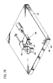
- FIG. 19 is a perspective view showing another embodiment of the present invention.
- FIGS. 6 through 12 an embodiment of a recording and reproducing apparatus according to the present invention is explained referring to FIGS. 6 through 12 .
- those corresponding to the parts in FIGS. 1 through 5 shall be given the same reference numerals and a detailed explanation thereof is omitted in FIGS. 6 through 12 .
- an existing cassette an NTSC method
- a higher cassette high vision method
- a VTR 8 mm video tape recorder
- an erroneous erasure prevention member 5 is slidably provided, for example, at a position adjacent to a corner inside a cassette casing 1 formed by combining top and bottom shells (not shown in the figure), to open and close an erroneous erasure prevention hole provided on the bottom surface 1 b of the cassette casing which is described later on by moving the erroneous erasure prevention member 5 in the longitudinal direction on the side surface 1 a.
- an existing erroneous erasure prevention hole 2 in order to prevent the erroneous erasure of data recorded on a magnetic tape with the existing format
- an erroneous erasure prevention hole 3 in order to prevent similarly the erroneous erasure of data recorded with the new (higher) format.
- Those existing and higher erroneous erasure prevention detecting switches 7 and 8 are provided at positions respectively corresponding to positions of the above described existing erroneous erasure prevention hole 2 and higher erroneous erasure prevention hole 3 inside a corner of a drive unit shown in FIG.
- each detecting switch has a detection pin; and an ON-state is detected when the detection pin is depressed by the cassette casing and an OFF-state is detected when the detection pin is not depressed due to being engaged with the erroneous erasure prevention hole, so that the open or closed state of the existing erroneous erasure prevention hole 2 and the higher erroneous erasure prevention hole 3 of the cassette 1 are detected.
- An example of the erroneous erasure prevention member 5 has a step-like shape formed of a plurality of bending portions as shown in FIG. 7 for example, and includes a lug portion 5 a for moving operation, a half-disc shaped protruding portion 5 b which opens and closes the erroneous erasure prevention hole and an display portion 5 c which indicates to be recordable in an display window 4 provided by making an opening in the side surface 1 a of the cassette casing.
- the erroneous erasure prevention member 5 is moved by laying a finger or the like on the lug portion 5 a projecting from the inside of the display window 4 on the side surface 1 a of the cassette casing so that the display portion 5 c is visible in the whole display window 4 .
- the erroneous erasure prevention hole 3 is not closed by the protruding portion 5 b of the erroneous erasure prevention member 5 to become the open state.
- a position of the erroneous erasure prevention member 5 at this time is a recordable position in which recording of the cassette can be performed.
- the erroneous erasure prevention member 5 is moved by laying a finger or the like on the lug portion 5 a of the erroneous erasure prevention member 5 projecting from the inside of the display window 4 on the side surface 1 a of the cassette casing, so that the display portion 5 c of the erroneous erasure prevention member 5 disappears from the display window 4 and a recording prohibition display panel 4 a disposed behind that member becomes visible.
- the erroneous erasure prevention hole 3 becomes the closed state by the protruding portion 5 b of the erroneous erasure prevention member 5 .
- a position of the erroneous erasure prevention member 5 at this time is a non-recordable position which prevents the cassette from being recorded.
- FIG. 9 is a configuration for performing the erroneous erasure prevention and the identification of the cassette according to this embodiment.
- the configuration includes a switch detection circuit 9 , a control circuit 10 and a recording and reproducing circuit 11 , so that a state of the erroneous erasure prevention hole provided in the casing of the cassette 1 can be detected by the existing erroneous erasure prevention detecting switch 7 and the higher erroneous erasure prevention detecting switch 8 which are connected to the switch detection circuit 9 .
- the switch detection circuit 9 converts a result of the detection performed by the lower and higher erroneous erasure prevention detecting switches 7 and 8 into a predetermined signal to output to the control circuit 10 .
- the control circuit 10 outputs a control command, which controls a recording and reproducing operation based on the output from the switch detection circuit 9 , to the recording and reproducing circuit 11 .
- the recording and reproducing circuit 11 performs recording on or reproduction from a magnetic tape 12 accommodated in the cassette 1 .
- FIGS. 10A and 10B schematically show a relevant part of a cassette and a recording and reproducing apparatus with cross-sectional views, respectively.
- FIGS. 10A and 10B show open and closed states of an erroneous erasure prevention member and an erroneous erasure prevention hole with respect to a higher cassette at a time when it is recordable and at a time when it is not recordable, respectively; and also, FIGS. 11A and 11B show open and closed states of an erroneous erasure prevention member and an erroneous erasure prevention hole with respect to an existing cassette at a time when it is recordable and at a time when it is not recordable, respectively.
- the existing erroneous erasure prevention hole 2 of the higher cassette 1 is always kept in the open state.
- the erroneous erasure prevention hole 3 becomes the open state in addition to the existing erroneous erasure prevention hole 2 which has been set in the open state in advance, then both the existing and higher erroneous erasure prevention detecting switches 7 and 8 are turned off. At this time, the higher cassette 1 becomes the recordable state.
- the erroneous erasure prevention hole 3 becomes the closed state although the existing erroneous erasure prevention hole 2 has been set in the open state in advance, then the existing erroneous erasure prevention detecting switch 7 is turned off and the higher erroneous erasure prevention detecting switch 8 is turned on. At this time, the higher cassette 1 becomes the non-recordable state.
- the erroneous erasure prevention member 103 is moved to the recordable position as shown in FIG. 11B , the erroneous erasure prevention hole 101 becomes the open state, then the existing erroneous erasure prevention detecting switch 7 is turned off and the higher erroneous erasure prevention detecting switch 8 is turned on. At this time, the existing cassette 100 becomes the non-recordable state.
- a flow of the erroneous erasure prevention and the format identification of the cassette according to the present invention is explained referring to a flow chart shown in FIG. 12 .
- an existing or a higher cassette is loaded into the VTR and it is judged whether or not the existing cassette is recordable (S 1 ).
- a state of the loaded cassette is confirmed by the ON/OFF-state of the lower erroneous erasure prevention detecting switch of the VTR.
- the existing erroneous erasure prevention detecting switch 7 is depressed to be turned on and therefore, it is judged that the existing cassette 100 is in a recordable state.
- the existing erroneous erasure prevention detecting switch 7 is turned on and the erroneous erasure prevention is cancelled. Accordingly, it is possible to record on and reproduce from the cassette 100 with the existing format.
- the higher erroneous erasure prevention detecting switch 8 is in the OFF-state, it is possible to record on and reproduce from the cassette 1 . Moreover, since the hole 3 for erroneous erasure prevention of the cassette 1 has been set in the open state in advance, there is no possibility that data is erroneously rewritten or deleted with the existing format.
- the identification of the cassette is performed by judging whether it is an existing or a higher format based on the data obtained from the reproduction so that the reproduction can be performed by an appropriate format, it is possible to utilize the existing cassette and the drive apparatus by adding only one piece of higher format erroneous erasure prevention detecting switch 8 to support the higher format.
- FIGS. 13A and 13B schematically show a relevant part of a cassette and a recording and reproducing apparatus with a cross-sectional view.
- FIGS. 14A and 14B show open and closed states of an erroneous erasure prevention member and an erroneous erasure prevention hole with respect to a higher cassette at a time when it is recordable and at a time when it is not recordable, respectively; and also, FIGS. 15A and 15B show open and closed state of an erroneous erasure prevention member and an erroneous erasure prevention hole with respect to an existing cassette at a time when it is recordable and at a time when it is not recordable, respectively.
- the erroneous erasure prevention member on the side surface of the cassette shown in FIG. 6 is not made to slide in the longitudinal direction, but is made to be capable of sliding in the widthwise direction and also an erroneous erasure prevention detecting switch is made to have a structure corresponding thereto. Further, similarly to the embodiment of FIG. 10 , the existing erroneous erasure prevention hole is kept always in the open state with respect to the higher cassette. Other structure than the above is the same as the embodiment of FIG. 10 .
- a reference numeral 20 denotes a cassette in which a U-shaped erroneous erasure prevention member 25 is slidably provided at a position adjacent to a corner inside a casing in the widthwise direction in the side surface 20 a , and also, the existing erroneous erasure prevention hole 2 is provided nearby at a predetermined position on the bottom surface 20 b of the cassette.
- the erroneous erasure prevention member 25 is structured to be approximately U-shaped having, for example, an upper convex portion 25 a to be used for a lug at the time of moving operation and a lower convex portion 25 b for depressing the erroneous erasure prevention detecting switch, and both the higher and lower convex portions are disposed to face the outside of the cassette. Further, the erroneous erasure prevention member includes a display portion 25 c which indicates that the cassette is recordable through an display window 23 provided by making an opening in the side surface 20 a of the cassette casing.
- a cut-out portion 24 is provided on the side surface 20 a of the cassette 20 so that the lower convex portion 25 b can be moved. Further, on a recording and reproducing apparatus side (not shown in the figure), the existing erroneous erasure prevention detecting switch 7 and an higher erroneous erasure prevention detecting switch 27 are provided at positions corresponding respectively to the above existing erroneous erasure prevention described hole 2 and erroneous erasure prevention member 25 .
- a projecting side 27 a is provided at the lower end portion of this higher erroneous erasure prevention detecting switch 27 .
- the projecting side 27 a is forced upward to become a rotated state to be nearly level having a center of rotation at a connecting point to the higher erroneous erasure prevention detecting switch 27 .
- the projecting side 27 a is brought in contact with the erroneous erasure prevention member 25 described later on, the projecting side 27 a is pushed to move downward to turn on the higher erroneous erasure prevention detecting switch 27 .
- the open or closed state of the existing erroneous erasure prevention hole 2 and the position of the erroneous erasure prevention member 25 are respectively detected by the existing erroneous erasure prevention detecting switch 7 and the higher erroneous erasure prevention detecting switch 27 which are provided respectively at the positions corresponding to the above described existing erroneous erasure prevention hole 2 and higher erroneous erasure prevention cut-out portion 24 on the VTR side.
- the existing cassette 100 is loaded into the recording and reproducing apparatus of this embodiment and when the erroneous erasure prevention member 103 is moved by laying a finger or the like on the lug portion 103 a to move in the longitudinal direction of the side surface 100 a so that the display portion 103 c becomes visible from the display window 102 as shown in FIG. 15A , the existing erroneous erasure prevention hole 101 on the bottom surface 100 b of the cassette casing is closed to turn on the existing erroneous erasure prevention detecting switch 7 .
- the higher erroneous erasure prevention detecting switch 27 is turned on since the projecting side 27 a is pressed by the side surface 100 a . At this time, the existing cassette 100 becomes the recordable state.
- the existing erroneous erasure prevention hole 101 on the bottom surface 100 b of the cassette casing becomes open to turn off the existing erroneous erasure prevention detecting switch 7 .
- the higher erroneous erasure prevention detecting switch 27 is being turned on since the projecting side 27 a is pressed by the side surface 100 a . At this time, the existing cassette 100 becomes the non-recordable state.
- FIGS. 16A and 16B show open and closed states of an erroneous erasure prevention member and an erroneous erasure prevention hole with respect to a higher cassette at a time when it is recordable and at a time when it is not recordable, respectively; and also, FIGS. 17A and 17B show open and closed states of an erroneous erasure prevention member and an erroneous erasure prevention hole with respect to an existing cassette at a time when it is recordable and at a time when it is not recordable, respectively.
- so-called a plastic-magnet for example, which is made of a magnetized plastic is used instead of the erroneous erasure prevention member 5 on the side surface of the higher cassette shown in FIG. 6 , and also, a hall element, for example, is used as an higher erroneous erasure prevention detecting switch 36 .
- the existing erroneous erasure prevention hole is also always kept in the open state with respect to the higher cassette in this embodiment.
- FIG. 16 and FIG. 17 the same reference numerals are given to those corresponding to the ones in FIGS. 10 and 11 , and the other structure is made to be the same as the embodiment of FIG. 6 .
- an higher cassette 30 is provided with a slidable erroneous erasure prevention member 33 made of, for example, the plastic-magnet at a position adjacent to a corner inside the cassette casing in the longitudinal direction, and also, the existing erroneous erasure prevention hole 2 is provided at a predetermined position on the bottom surface of the cassette.
- the existing erroneous erasure prevention detecting switch 7 and the higher erroneous erasure prevention detecting switch 36 made of a hall element are provided at positions corresponding respectively to the above described existing erroneous erasure prevention hole 2 and higher erroneous erasure prevention member 33 .
- the hall element constituting the higher erroneous erasure prevention detecting switch 36 has polarities of the S-pole and the N-pole and is disposed in the vicinity of the plastic-magnet constituting the erroneous erasure prevention member 33 with the cassette casing in between.
- this plastic-magnet When this plastic-magnet is moved, the polarity changes in a portion close to the hall element and its resultant alteration of a magnetic field is detected from an alteration of an electromotive force generated in the hall element. Accordingly, a position of the erroneous erasure prevention member 33 made of this plastic-magnet is detected to identify a state of the cassette 30 .
- the cassette is set to the recordable state when the N-pole of the plastic-magnet comes close to the hall element, for example, and is set to the non-recordable state when the S-pole of the plastic-magnet comes close to the hall element. Further, when the magnetic field does not exist in the vicinity of the plastic-magnet, it is made to be non-recordable.
- the higher cassette 30 of this embodiment when the plastic-magnet constituting the erroneous erasure prevention member 33 is moved by laying a finger or the like on a lug portion 33 a in the longitudinal direction on the side surface 30 a so that an display portion 33 c of the erroneous erasure prevention member 33 becomes visible from the display window 32 as shown in FIG. 16A , the existing erroneous erasure prevention hole 2 has been set in the open state in advance, and also, the N-pole of the plastic-magnet is brought close to the hall element constituting the higher erroneous erasure prevention detecting switch 36 . At this time, the higher cassette 30 becomes the recordable state.
- the existing cassette 100 provided with the erroneous erasure prevention member 103 for the existing format
- the erroneous erasure prevention member 103 when the erroneous erasure prevention member 103 is moved by laying a finger or the like on the lug portion 103 a in the longitudinal direction on the side surface 100 a so that the display portion 103 c is visible from the display window 102 as shown in FIG. 17A , the erroneous erasure prevention hole 101 becomes the closed state.
- the existing erroneous erasure prevention detecting switch 7 turns on, and there is no magnetic field generated in the vicinity of the higher erroneous erasure prevention detecting switch 36 made of the hall element. Accordingly, the existing cassette 100 becomes the recordable state.
- the erroneous erasure prevention hole 101 becomes the open state.
- the existing erroneous erasure prevention detecting switch 7 turns off, and there is no magnetic field generated in the vicinity of the higher erroneous erasure prevention detecting switch 36 made of the hall element. Accordingly, the existing cassette 100 becomes the non-recordable state.
- the higher erroneous erasure prevention member 33 is made of the plastic-magnet and also the higher erroneous erasure prevention detecting switch 36 is made of the hall element, the higher erroneous erasure prevention means can be made a non-contact detection method, and therefore, a mechanical loss can be eliminated.
- this embodiment has a structure as described above, it can be easily understood that other operational effectiveness similar to that of the embodiment shown in FIG. 6 can be obtained.
- FIGS. 18 and 19 Another embodiment of a recording and reproducing apparatus according to the present invention is explained referring to FIGS. 18 and 19 .
- the cassette shown in FIG. 6 is applied to a disc cartridge of a disc type recording medium such as, for example, an optical disc.
- FIG. 18 is a perspective view showing, for example, an example of a DVR disc cartridge
- FIG. 19 is a perspective view showing an example of a recording and reproducing apparatus to which the above mentioned DVR disc cartridge is loaded.
- the DVR disc cartridge In the DVR disc cartridge, recording and reproduction is performed on a disc using a blue color or blue-violet color laser, and the DVR cartridge is placed in a higher order than a DVD disc cartridge which uses a red color laser.
- an erroneous erasure prevention member 42 is arranged, for example, at a position adjacent to a corner inside a DVR disc cartridge casing 40 , and also, a lower erroneous erasure prevention hole 50 and a higher erroneous erasure prevention hole 51 are respectively provided on the bottom surface of the cartridge.
- An display window 41 is provided on a side surface 40 a of the casing so that a moving operation can be performed by laying a finger or the like on a lug portion 42 a .
- a reference numeral 40 b denotes a see-through window and a portion indicated by a dotted line denotes an opening portion 40 c having a shutter provided on the bottom surface, in which while a DVR disc is loaded, the opening portion 40 c opens and the DVR disc is irradiated with a laser beam from a pickup described later on, so that recording and reproduction of a signal can be performed.
- a reference numeral 43 denotes an example of a chassis of a recording and reproducing apparatus for a DVR, in which a disc mounted on a turntable 47 is rotated by a spindle motor 46 and a signal is recorded and reproduced by pickups 48 and 49 .
- Those pickups 48 and 49 respectively emit, for example, a red laser which has been used conventionally and a blue or blue-violet laser which has a shorter wavelength to realize high density recording to perform recording and reproduction of a signal from a DVR disc cartridge and a DVD disc cartridge and to perform reproduction from a playback-only DVD disc.
- an existing erroneous erasure prevention detecting switch 44 and a higher erroneous erasure prevention detecting switch 45 are arranged at positions corresponding respectively to the existing erroneous erasure prevention hole 50 and the higher erroneous erasure prevention hole 51 which are located in the vicinity of a corner of the chassis 43 when the disc cartridge 40 is loaded into the recording and reproducing apparatus.
- the erroneous erasure prevention and the format identification of the signal of the DVR disc or the DVD disc accommodated in the disc cartridge can be performed in accordance with the flow chart shown in FIG. 12 by those existing erroneous erasure prevention detecting switch 44 and higher erroneous erasure prevention detecting switch 45 .
- the present invention may also be considered to perform the erroneous erasure prevention and the identification of a cassette by making the structure of an erroneous erasure prevention detecting switch optical, for example, to detect transmitted light from a detection hole provided on a cassette side.
- an erroneous erasure prevention detecting switch optical, for example, to detect transmitted light from a detection hole provided on a cassette side.
- the present invention can be applied to perform the identification of cassettes of various formats such as the format identification of recording media recorded in different MPEG method formats.
- the recording medium cassette according to the present invention is not limited to the cassette incorporating a recordable and reproducible tape or the cartridge incorporating recordable and reproducible disc which have been explained in the above embodiments; and it is obvious that the present invention is also applicable to a recording medium package in a block or card shape, in which an erroneous erasure prevention means is included and a recording medium such as a hard disc drive, a semiconductor memory and a hologram memory is incorporated.
- the erroneous erasure prevention means is composed of a magnetized member having a polarity and the erroneous erasure prevention is performed by detecting the alteration of the magnetic field generated by the member, a non-contact detection method can be obtained and there is an advantage of eliminating a mechanical loss.
- the identification of a cassette can be performed by adding only one detection hole, because one detection hole is used in common for detecting whether the cassette is of a new format or of an existing format and for preventing the erroneous erasure by utilizing the fact that the cassette at the time when the detection hole for the new format is in the closed state and the cassette for the existing format which does not have the detection hole are detected as if they were in the same state when viewed from the drive unit side.
Landscapes
- Engineering & Computer Science (AREA)
- Computer Security & Cryptography (AREA)
- Packaging Of Annular Or Rod-Shaped Articles, Wearing Apparel, Cassettes, Or The Like (AREA)
- Recording Or Reproducing By Magnetic Means (AREA)
- Management Or Editing Of Information On Record Carriers (AREA)
Applications Claiming Priority (3)
| Application Number | Priority Date | Filing Date | Title |
|---|---|---|---|
| JP2002-118031 | 2002-04-19 | ||
| JP2002118031A JP2003317346A (ja) | 2002-04-19 | 2002-04-19 | 記録再生装置及び記録媒体カセット |
| PCT/JP2003/004850 WO2003090223A1 (fr) | 2002-04-19 | 2003-04-16 | Appareil de copie/enregistrement et cassette support d'enregistrement |
Publications (2)
| Publication Number | Publication Date |
|---|---|
| US20050237647A1 US20050237647A1 (en) | 2005-10-27 |
| US7113368B2 true US7113368B2 (en) | 2006-09-26 |
Family
ID=29243513
Family Applications (1)
| Application Number | Title | Priority Date | Filing Date |
|---|---|---|---|
| US10/511,667 Expired - Fee Related US7113368B2 (en) | 2002-04-19 | 2003-04-16 | Recording and reproducing apparatus for preventing erroneous erasure |
Country Status (5)
| Country | Link |
|---|---|
| US (1) | US7113368B2 (https=) |
| JP (1) | JP2003317346A (https=) |
| KR (1) | KR20040097366A (https=) |
| CN (1) | CN1659649A (https=) |
| WO (1) | WO2003090223A1 (https=) |
Cited By (1)
| Publication number | Priority date | Publication date | Assignee | Title |
|---|---|---|---|---|
| US8407765B2 (en) | 2006-08-22 | 2013-03-26 | Centurylink Intellectual Property Llc | System and method for restricting access to network performance information tables |
Families Citing this family (1)
| Publication number | Priority date | Publication date | Assignee | Title |
|---|---|---|---|---|
| US7667872B2 (en) * | 2005-11-14 | 2010-02-23 | Microsoft Corporation | Gamut mapping and rendering intent management system |
Citations (9)
| Publication number | Priority date | Publication date | Assignee | Title |
|---|---|---|---|---|
| US5091901A (en) * | 1989-04-06 | 1992-02-25 | Sony Corporation | Disc cartridge with dual identification elements |
| JPH0636451A (ja) | 1992-07-17 | 1994-02-10 | Alpine Electron Inc | デジタルコンパクトカセットテーププレーヤー |
| JPH06267233A (ja) | 1993-03-16 | 1994-09-22 | Sanyo Electric Co Ltd | 磁気記録再生装置 |
| EP0694920A2 (en) | 1994-07-29 | 1996-01-31 | Kabushiki Kaisha Toshiba | A cartridge for housing a disc and a disc apparatus for handling the same cartridge |
| US5506736A (en) * | 1992-11-25 | 1996-04-09 | Sony Corporation | Memory arrangement for tape cassettes used in recording and/or reproduction |
| US5786967A (en) * | 1989-03-13 | 1998-07-28 | Imation Corp. | Tape cartridge including an indication device to distinguish between cartridges having different characteristics but nearly identical physical characteristics |
| EP0926674A2 (en) | 1997-12-24 | 1999-06-30 | Aiwa Co., Ltd. | Data storage cassette and data recording and reproducing device |
| US6239950B1 (en) * | 1996-03-26 | 2001-05-29 | Mitsumi Electric Co., Ltd. | High density flexible disk drive having a large capacity detecting switch provided at a position corresponding to a large capacity identifier hole provided in a case of a large capacity flexible disk |
| US20050117881A1 (en) * | 2002-06-06 | 2005-06-02 | Nobuaki Baba | Recorder and cassette containing recording medium |
Family Cites Families (1)
| Publication number | Priority date | Publication date | Assignee | Title |
|---|---|---|---|---|
| US6899959B2 (en) * | 2002-02-12 | 2005-05-31 | Komag, Inc. | Magnetic media with improved exchange coupling |
-
2002
- 2002-04-19 JP JP2002118031A patent/JP2003317346A/ja active Pending
-
2003
- 2003-04-16 CN CN038136511A patent/CN1659649A/zh active Pending
- 2003-04-16 WO PCT/JP2003/004850 patent/WO2003090223A1/ja not_active Ceased
- 2003-04-16 KR KR10-2004-7016708A patent/KR20040097366A/ko not_active Withdrawn
- 2003-04-16 US US10/511,667 patent/US7113368B2/en not_active Expired - Fee Related
Patent Citations (12)
| Publication number | Priority date | Publication date | Assignee | Title |
|---|---|---|---|---|
| US5786967A (en) * | 1989-03-13 | 1998-07-28 | Imation Corp. | Tape cartridge including an indication device to distinguish between cartridges having different characteristics but nearly identical physical characteristics |
| US5091901A (en) * | 1989-04-06 | 1992-02-25 | Sony Corporation | Disc cartridge with dual identification elements |
| JPH0636451A (ja) | 1992-07-17 | 1994-02-10 | Alpine Electron Inc | デジタルコンパクトカセットテーププレーヤー |
| US5506736A (en) * | 1992-11-25 | 1996-04-09 | Sony Corporation | Memory arrangement for tape cassettes used in recording and/or reproduction |
| JPH06267233A (ja) | 1993-03-16 | 1994-09-22 | Sanyo Electric Co Ltd | 磁気記録再生装置 |
| EP0694920A2 (en) | 1994-07-29 | 1996-01-31 | Kabushiki Kaisha Toshiba | A cartridge for housing a disc and a disc apparatus for handling the same cartridge |
| JPH0845234A (ja) | 1994-07-29 | 1996-02-16 | Toshiba Corp | ディスクが収納されるカートリッジとこのカートリッジを扱うディスク装置 |
| US6239950B1 (en) * | 1996-03-26 | 2001-05-29 | Mitsumi Electric Co., Ltd. | High density flexible disk drive having a large capacity detecting switch provided at a position corresponding to a large capacity identifier hole provided in a case of a large capacity flexible disk |
| EP0926674A2 (en) | 1997-12-24 | 1999-06-30 | Aiwa Co., Ltd. | Data storage cassette and data recording and reproducing device |
| JPH11185441A (ja) | 1997-12-24 | 1999-07-09 | Aiwa Co Ltd | データストレージ用カセットおよびデータ用記録再生装置 |
| US6227477B1 (en) * | 1997-12-24 | 2001-05-08 | Aiwa Co., Ltd. | Data storage cassette and data recording and reproducing device |
| US20050117881A1 (en) * | 2002-06-06 | 2005-06-02 | Nobuaki Baba | Recorder and cassette containing recording medium |
Cited By (1)
| Publication number | Priority date | Publication date | Assignee | Title |
|---|---|---|---|---|
| US8407765B2 (en) | 2006-08-22 | 2013-03-26 | Centurylink Intellectual Property Llc | System and method for restricting access to network performance information tables |
Also Published As
| Publication number | Publication date |
|---|---|
| WO2003090223A1 (fr) | 2003-10-30 |
| JP2003317346A (ja) | 2003-11-07 |
| CN1659649A (zh) | 2005-08-24 |
| US20050237647A1 (en) | 2005-10-27 |
| KR20040097366A (ko) | 2004-11-17 |
Similar Documents
| Publication | Publication Date | Title |
|---|---|---|
| US6603725B2 (en) | Disk cartridge apparatus | |
| US7113368B2 (en) | Recording and reproducing apparatus for preventing erroneous erasure | |
| WO2002061741A1 (en) | Optical disc, optical disc reproducing method and apparatus, and recording method | |
| US7515370B2 (en) | Recorder and cassette containing recording medium | |
| US7555763B2 (en) | Disk cartridge | |
| JP4053390B2 (ja) | ディスクカートリッジ | |
| JPH0370875B2 (https=) | ||
| JP4148284B2 (ja) | 情報記録再生装置、制御方法 | |
| JPS61965A (ja) | 記録媒体の種類判別装置 | |
| KR100583309B1 (ko) | 디스크 카트리지 | |
| JP2008282466A (ja) | 記録媒体駆動装置及び記録媒体の媒体情報取得方法 | |
| JP3093808B2 (ja) | 情報記録再生装置 | |
| JP2937669B2 (ja) | ディスク装置 | |
| JPH10334629A (ja) | ディスクカートリッジ及びディスク記憶装置 | |
| JP2928039B2 (ja) | 光ディスク装置 | |
| US20040246826A1 (en) | Tray and recording/reproducing apparatus | |
| JPH0676453A (ja) | オートチェンジ機能を有する記録媒体の再生装置 | |
| JPH0963241A (ja) | 磁気ディスクカートリッジ | |
| JPH06267232A (ja) | ディスクカートリッジ及びディスク記録/再生装置 | |
| JPH09231667A (ja) | 記録媒体の記録可否検知装置 | |
| JP2000322815A (ja) | 光磁気記録再生装置 | |
| JPH0630986U (ja) | ディスク装置 | |
| JPH11265568A (ja) | ディスク記録再生装置 | |
| KR20000074525A (ko) | 디스크 드라이브용 자기 디스켓 | |
| KR20050017710A (ko) | 광디스크 드라이브의 트레이 개폐 검출장치 및 방법 |
Legal Events
| Date | Code | Title | Description |
|---|---|---|---|
| AS | Assignment |
Owner name: SONY CORPORATION, JAPAN Free format text: ASSIGNMENT OF ASSIGNORS INTEREST;ASSIGNORS:FUKUTANI, TAKAHIRO;BABA, NOBUAKI;OOTSUKA, MINORU;AND OTHERS;REEL/FRAME:016679/0514;SIGNING DATES FROM 20041013 TO 20041022 |
|
| REMI | Maintenance fee reminder mailed | ||
| LAPS | Lapse for failure to pay maintenance fees | ||
| STCH | Information on status: patent discontinuation |
Free format text: PATENT EXPIRED DUE TO NONPAYMENT OF MAINTENANCE FEES UNDER 37 CFR 1.362 |
|
| FP | Lapsed due to failure to pay maintenance fee |
Effective date: 20100926 |