US6952290B2 - Sensing of original size - Google Patents
Sensing of original size Download PDFInfo
- Publication number
- US6952290B2 US6952290B2 US09/818,150 US81815001A US6952290B2 US 6952290 B2 US6952290 B2 US 6952290B2 US 81815001 A US81815001 A US 81815001A US 6952290 B2 US6952290 B2 US 6952290B2
- Authority
- US
- United States
- Prior art keywords
- original
- ambient light
- photoelectric converter
- light
- light source
- Prior art date
- Legal status (The legal status is an assumption and is not a legal conclusion. Google has not performed a legal analysis and makes no representation as to the accuracy of the status listed.)
- Expired - Lifetime, expires
Links
Images


Classifications
-
- H—ELECTRICITY
- H04—ELECTRIC COMMUNICATION TECHNIQUE
- H04N—PICTORIAL COMMUNICATION, e.g. TELEVISION
- H04N1/00—Scanning, transmission or reproduction of documents or the like, e.g. facsimile transmission; Details thereof
- H04N1/00681—Detecting the presence, position or size of a sheet or correcting its position before scanning
- H04N1/00684—Object of the detection
- H04N1/00708—Size or dimensions
-
- H—ELECTRICITY
- H04—ELECTRIC COMMUNICATION TECHNIQUE
- H04N—PICTORIAL COMMUNICATION, e.g. TELEVISION
- H04N1/00—Scanning, transmission or reproduction of documents or the like, e.g. facsimile transmission; Details thereof
- H04N1/00681—Detecting the presence, position or size of a sheet or correcting its position before scanning
- H04N1/00729—Detection means
- H04N1/00734—Optical detectors
- H04N1/00737—Optical detectors using the scanning elements as detectors
-
- H—ELECTRICITY
- H04—ELECTRIC COMMUNICATION TECHNIQUE
- H04N—PICTORIAL COMMUNICATION, e.g. TELEVISION
- H04N1/00—Scanning, transmission or reproduction of documents or the like, e.g. facsimile transmission; Details thereof
- H04N1/00681—Detecting the presence, position or size of a sheet or correcting its position before scanning
- H04N1/00742—Detection methods
- H04N1/00748—Detecting edges, e.g. of a stationary sheet
-
- H—ELECTRICITY
- H04—ELECTRIC COMMUNICATION TECHNIQUE
- H04N—PICTORIAL COMMUNICATION, e.g. TELEVISION
- H04N1/00—Scanning, transmission or reproduction of documents or the like, e.g. facsimile transmission; Details thereof
- H04N1/00681—Detecting the presence, position or size of a sheet or correcting its position before scanning
- H04N1/00742—Detection methods
- H04N1/0075—Detecting a change in reflectivity
Definitions
- the present invention relates to sensing of an original size and, more particularly, to an original size sensing apparatus and method suited to sensing the size of an original to be read by, e.g., a digital copying machine, scanner, or facsimile apparatus.
- the present invention has been made in consideration of the above situation, and has as its object to realize efficient original size sensing insusceptible to the influence of ambient light.
- an original size sensing apparatus incorporated into an apparatus, or an image reading apparatus, or a copying apparatus or a facsimile apparatus which comprises a photoelectric converter for reading an image of an original placed on a platen, and a light source for irradiating the original with light, comprising: an ambient light determination unit for determining the presence/absence of incidence of ambient light on the basis of an output from the photoelectric converter while the light source is kept off; and an original size determination unit for determining, when the ambient light determination unit determines that ambient light is incident, the size of an original placed on the platen on the basis of output from the photoelectric converter except a range in which the ambient light is incident, while the light source is kept on.
- an original size sensing apparatus incorporated into an apparatus, or an image reading apparatus, or a copying apparatus or a facsimile apparatus which comprises a photoelectric converter for reading an image of an original placed on a platen, and a light source for irradiating the original with light
- an ambient light determination unit for determining the presence/absence of incidence of ambient light on the basis of an output from the photoelectric converter while the light source is kept off
- an original size determination unit for determining, when the ambient light determination unit determines that ambient light is incident, the size of an original placed on the platen on the basis of output from a range, of the photoelectric converter, from a boundary between a region in which the ambient light is not incident and a region in which the ambient light is incident to a predetermined position, while the light source is kept on.
- an original size sensing method for an apparatus which comprises a photoelectric converter for reading an image of an original placed on a platen, and a light source for irradiating the original with light, comprising: an ambient light determination step of determining the presence/absence of incidence of ambient light on the basis of an output from the photoelectric converter while the light source is kept off; and an original size determination step of determining, when it is determined in the ambient light determination step that ambient light is incident, the size of an original placed on the platen on the basis of output from the photoelectric converter except a range in which the ambient light is incident, while the light source is kept on.
- An original size sensing method for an apparatus which comprises a photoelectric converter for reading an image of an original placed on a platen having an original size index plate indicating placement position references of various fixed-form originals, and a light source for irradiating the original with light, comprising: an ambient light determination step of determining the presence/absence of incidence of ambient light on the basis of an output from the photoelectric converter while the light source is kept off; and an original size determination step of determining, when it is determined in the ambient light determination step that ambient light is incident, the size of an original placed on the platen on the basis of output from a range, of the photoelectric converter, from a boundary between a region in which the ambient light is not incident and a region in which the ambient light is incident to a predetermined position, while the light source is kept on.
- FIG. 1 a block diagram showing the arrangement of a control system of image reading apparatuses according to the first to fourth embodiments of the present invention
- FIG. 2 is a view showing the arrangement of an image reading system of the image reading apparatuses according to the first to fourth embodiments of the present invention
- FIG. 3 is a top view showing the arrangement of a platen of the image reading apparatuses according to the first and second embodiments of the present invention
- FIG. 4 is a top view showing a sensing point used in original size determination on a platen glass of the image reading apparatuses according to the first and second embodiments of the present invention
- FIG. 5 is a side view showing the positional relationship between the image reading apparatuses according to the first and second embodiments of the present invention and a fluorescent lamp;
- FIG. 6 is a top view showing the positional relationship between the image reading apparatuses according to the first and second embodiments of the present invention and the fluorescent lamp;
- FIG. 7 is a graph showing the relationship between the CCD output and the main scan position in the image reading apparatuses according to the first and second embodiments of the present invention.
- FIG. 8 is a graph showing the relationship between the CCD output and the main scan position and a range excluded from sensing in the image reading apparatus according to the first embodiment of the present invention.
- FIG. 9 is a graph showing the relationship between the CCD output and the main scan position and the range excluded from sensing in the image reading apparatus according to the first embodiment of the present invention.
- FIG. 10 is a graph showing the relationship between the CCD output and the main scan position and a range excluded from sensing in the image reading apparatus according to the second embodiment of the present invention.
- FIG. 11 is a graph showing the relationship between the CCD output and the main scan position and the range excluded from sensing in the image reading apparatus according to the second embodiment of the present invention.
- FIG. 12 is a view showing the main scan size determination results and the original sensor determination results in the image reading apparatuses according to the first to fourth embodiments of the present invention.
- FIG. 13 is a flow chart showing the original size sensing process of the image reading apparatus according to the first embodiment of the present invention.
- FIG. 14 is a flow chart showing the original size sensing process of the image reading apparatus according to the second embodiment of the present invention.
- FIG. 15 is a top view showing the arrangement of a platen of the image reading apparatuses according to the third embodiment of the present invention.
- FIG. 16 is a top view showing a sensing point used in original size determination on a platen glass of the image reading apparatuses according to the third embodiment of the present invention.
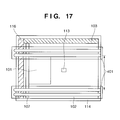
- FIG. 17 is a top view showing the positional relationship between the image reading apparatuses according to the third embodiment of the present invention and the fluorescent lamp;
- FIG. 18 is a graph showing the relationship between the CCD output and the main scan position in the image reading apparatuses according to the third embodiment of the present invention.
- FIG. 19 is a graph showing the relationship between the CCD output and the main scan position and a range excluded from sensing in the image reading apparatus according to the third embodiment of the present invention.
- FIG. 20 is a graph showing the relationship between the CCD output and the main scan position and the range excluded from sensing in the image reading apparatus according to the third embodiment of the present invention.
- FIG. 21 is a graph showing the relationship between the CCD output and the main scan position in the image reading apparatuses according to the fourth embodiment of the present invention.
- FIG. 22 is a graph showing the relationship between the CCD output and the main scan position and a range excluded from sensing in the image reading apparatus according to the fourth embodiment of the present invention.
- FIG. 23 is a flow chart showing the original size sensing process of the image reading apparatus according to the fourth embodiment of the present invention.
- FIG. 24 is a view showing the configuration of the stored contents of a storage medium storing programs and related data according to the first to fourth embodiments of the present invention.
- FIG. 25 is a view showing the concept by which the programs and related data according to the first to fourth embodiments of the present invention are supplied from the storage medium to the apparatus.
- FIG. 2 is a view showing the arrangement of an image reading system of an image reading apparatus according to the first embodiment of the present invention.
- FIG. 3 is a top view showing the arrangement of a platen glass of the image reading apparatus according to the first embodiment of the present invention.
- the image reading apparatus according to the first embodiment of the present invention is a general digital image reading apparatus to which original size sensing of the present invention is applied.
- a platen glass 102 a platen glass 102 , an optical base 107 having a lamp 105 and a mirror 106 , an optical base 110 having mirrors 108 and 109 , a lens 111 , a CCD 112 , and an original size sensor 113 are arranged in a housing 114 .
- Reference numeral 101 in FIG. 2 denotes an original.
- the platen glass 102 forms the upper portion of the housing 114 , and the original 101 to be read is placed on this platen glass 102 .
- An original size label 103 is arranged on the perimeter of the platen glass 102 .
- an original alignment mark 104 is formed in a reference registration position at the upper left corner shown in FIG. 3 . Fixed-size originals are placed as shown in FIG. 3 .
- the lamp 105 of the optical base 107 irradiates the original surface with light.
- the mirror 106 of the optical base 107 reflects the light emitted from the lamp 105 and reflected by the original.
- the mirrors 108 and 109 of the optical base 110 reflect the light reflected by the mirror 106 of the optical base 107 , thereby directing the reflected light toward the lens 111 .
- This lens 111 concentrates the light from the original surface, which is guided by the optical base 110 .
- the CCD 112 is a photoelectric converting element for receiving the light from the original surface, which is concentrated by the lens 111 , and for photoelectrically converting the light.
- the original size sensor 113 senses the original size in the sub-scan direction of the original 101 placed on the platen glass 102 . This original size sensor 113 outputs, by a binary number, the presence/absence of an original, at the position of the original size sensor 113 , on the platen glass 102 .
- Original reading is performed using the above arrangement.
- FIG. 1 is a block diagram showing the arrangement of a control system of the image reading apparatus according to the first embodiment of the present invention.
- This control system of the image reading apparatus according to the first embodiment of the present invention comprises the lamp 105 , the CCD 112 , the original size sensor 113 , an A/D converter 201 , an optical motor 202 , and a scanner controller 203 .
- the CCD 112 reads an original by receiving light from the original surface as described above.
- the A/D converter 201 performs analog-to-digital conversion on the output signal from the CCD 112 .
- the optical motor 202 moves the optical bases 107 and 110 to scan the original.
- the lamp 105 irradiates the original surface with light as described above.
- the original size sensor 113 senses the presence/absence of an original in the sub-scan direction of an original as described above.
- the scanner controller 203 controls the CCD 112 , the optical motor 202 , the lamp 105 , and the original size sensor 113 , and senses the length in the main scan direction of an original from an output digital signal from the A/D converter 201 . Also, the scanner controller 203 controls the original size sensor 113 to determine the presence/absence of an original in the sub-scan direction. On the basis of these two sensing results, the scanner controller 203 determines the original size. Additionally, this scanner controller 203 executes original size sensing processes shown in flow charts of FIG. 13 (first embodiment) and FIG. 14 (second embodiment) to be described later.
- FIG. 4 is a top view showing a sensing point used in original size determination on the platen glass of the image reading apparatus according to the first embodiment of the present invention.
- the original size sensor (reflection sensor) 113 for sensing the presence/absence of an original in the sub-scan direction is positioned at the sensing point shown in FIG. 4 .
- the optical base 107 is placed at the position shown in FIG. 4 and the CCD 112 reads the original only in the main scan direction, thereby sensing the original width in the main scan direction.
- FIG. 13 is a flow chart showing the procedure of an original size sensing process in the first embodiment of the present invention.
- the scanner controller 203 of the image reading apparatus controls the original size sensor 113 to determine the presence/absence of an original at the sensing position (i.e., the mounted position of the original size sensor 113 ) on the basis of a binary output signal from the original size sensor 113 (step S 131 ).
- the scanner controller 203 then turns off the lamp 105 and causes the CCD 12 to read one line of the original (step S 132 ).
- FIG. 7 shows an example of the read data.
- light from the fluorescent lamp 401 i.e., ambient light
- the CCD 112 is incident on the CCD 112 as indicated by 701 in FIG. 7 .
- a portion where the original is placed on the platen glass 102 is shielded from the light from the fluorescent lamp 401 above the image reading apparatus. Therefore, a signal value in this portion becomes lower than that in a portion where no original is present.
- the scanner controller 203 causes the A/D converter 201 to convert the output signal from the CCD 112 into a digital signal, and determines the presence/absence of ambient light in the main scan direction on the basis of a preset threshold value Th1 (step S 133 ). If no ambient light is found (NO in step S 133 ), original size sensing is performed by another method. When this is the case, any conventional method which is effective in the absence of ambient light can be used. If ambient light is found, the scanner controller 203 excludes a pixel range of the CCD 112 , from which a signal value higher than the threshold value Th1 is output, from a pixel range to be used in original width sensing (step S 134 ). FIG. 8 shows the excluded range. The scanner controller 203 then turns on the lamp 105 and causes the CCD 112 to read original surface information (step S 135 ).
- signals can be read out only from a pixel range of the CCD 112 , except for the pixel range excluded in step S 134 . It is also possible to once read out signals from all pixels of the CCD 112 and discard a signal corresponding to the pixel range excluded in step S 134 from the readout signals.
- FIG. 9 shows an example of data read by the latter method. As shown in FIG. 9 , a signal corresponding to light reflected by the original 101 and a signal corresponding to light inputted from the fluorescent lamp 401 are obtained. From these signals, a signal readout from pixels in the excluded range (a signal in a hatched portion) is discarded.
- the scanner controller 203 causes the A/D converter 201 to convert the output signal from the CCD 112 into a digital signal, and determines the presence/absence of reflected light from the original on the basis of the preset threshold value Th2 (step S 136 ). This determination is performed for a signal outside the pixel range excluded in step S 134 . If no reflected light is found, another processing is performed. If reflected light is found, the scanner controller 203 determines that the range in the main scan direction within which the reflected light is found is the range in which the original exists (step S 137 ). Accordingly, it is possible to determine whether a size corresponding to the original width in the main scan direction is either of B 6 and B 5 R, or either of A 5 and A 4 R, or either of B 5 and B 4 , or either of A 4 and A 3 .
- the scanner controller 203 determines the original size by looking up a table shown in FIG. 12 (step S 138 ).
- ambient light is sensed by turning off the lamp 105 of the image reading apparatus, so sensing errors caused by ambient light can be reduced. Also, a range in the main scan direction where ambient light is found is excluded in the original size sensing. This can realize efficient original size sensing insusceptible to the influence of ambient light. Furthermore, it is possible to reduce time to sense the original size and increase efficiency in the original size sensing.
- An image reading system of an image reading apparatus has the same arrangement as the first embodiment explained above with reference to FIG. 2 , so a detailed description thereof will be omitted.
- control system of the image reading apparatus according to the second embodiment of the present invention has the same arrangement as the first embodiment explained above with reference to FIG. 1 , so a detailed description thereof will be omitted.
- FIG. 14 is a flow chart showing the procedure of an original size sensing process in the second embodiment of the present invention.
- a scanner controller 203 of the image reading apparatus controls an original size sensor 113 to determine the presence/absence of an original at the sensing position (i.e., the mounted position of the original size sensor 113 ) on the basis of a binary output signal from the original size sensor 113 (step S 141 ).
- the scanner controller 203 then turns off a lamp 105 and causes a CCD 112 to read one line of the original (step S 142 ).
- FIG. 7 shows an example of the read data.
- light from the fluorescent lamp 401 as ambient light, is incident on the CCD 112 as indicated by 701 in FIG. 7 .
- an area where the original is placed on a platen glass 102 is shielded from the light from the fluorescent lamp 401 above the image reading apparatus. Therefore, a signal value in this portion becomes lower than that in a portion where no original is present.
- the scanner controller 203 causes an A/D converter 201 to convert the output signal from the CCD 112 into a digital signal, and determines the presence/absence of ambient light in the main scan direction on the basis of a preset threshold value Th1 (step S 143 ). If no ambient light exists (NO in step S 143 ), original size sensing is performed by another method. When this is the case, any conventional method which is effective in the absence of ambient light can be used.
- the scanner controller 203 sets only a pixel range closer to an original alignment mark than a boundary point between an ambient light absent range (i.e., a range in which the signal value is lower than the threshold value Th1) and an ambient light present range (i.e., a range in which the signal value is higher than the threshold value Th1), as an effective sensing range (step S 144 ).
- FIG. 10 shows the excluded range.
- the scanner controller 203 turns on the lamp 105 and causes the CCD 112 to read original surface information (step S 145 ).
- signals can be read out only from a pixel range of the CCD 112 , within the effective sensing range set in step S 144 . It is also possible to once read out signals from all pixels of the CCD 112 and extract only a signal corresponding to the effective sensing range set in step S 144 .
- FIG. 11 shows an example of data read by the latter method.
- the scanner controller 203 causes the A/D converter 201 to convert the output signal from the CCD 112 into a digital signal, and determines the presence/absence of reflected light from the original on the basis of the preset threshold value Th2 (step S 146 ). This determination is performed for a signal in the effective sensing range set in step S 144 . If no reflected light is found, another processing is performed. If reflected light is found, the scanner controller 203 determines that the range in the main scan direction within which the reflected light is found is the range in which the original exists (step S 147 ). Accordingly, it is possible to determine whether a size corresponding to the original width in the main scan direction is either of B 6 and B 5 R, or either of A 5 and A 4 R, or either of B 5 and B 4 , or either of A 4 and A 3 .
- the scanner controller 203 determines the original size by looking up a table shown in FIG. 12 (step S 148 ).
- ambient light is sensed by turning off the lamp 105 of the image reading apparatus, so sensing errors caused by ambient light can be reduced.
- an original alignment mark 104 is added to a reference registration portion of the platen glass 102 of the image reading apparatus.
- this mark 104 When an original is placed to be aligned with this mark 104 , only a range closer to the original alignment mark 104 than the boundary point between the range within which no ambient light is found and the range within which ambient light is found can be set as an effective sensing range. This can realize efficient original size sensing insusceptible to the influence of ambient light. Furthermore, it is possible to reduce time to sense the original size and increase efficiency in the original size sensing.
- An image reading system of an image reading apparatus has the same arrangement as the first embodiment explained above with reference to FIG. 2 , so a detailed description thereof will be omitted.
- a control system of the image reading apparatus according to the third embodiment of the present invention has the same arrangement as the first embodiment explained above with reference to FIG. 1 , so a detailed description thereof will be omitted.
- FIG. 15 is a top view showing the arrangement of a platen glass of the image reading apparatus according to the third embodiment of the present invention.
- the difference between the configuration of the third embodiment and that of the first and second embodiments is that another original size label 116 is arranged along the perimeter of the platen glass 102 in the main scan direction in addition to the original size label 103 which is arranged along the perimeter in the sub-scan direction, and an original is placed as shown in FIG. 15 .
- FIG. 16 is a top view showing a sensing point used in original size determination on the platen glass of the image reading apparatus according to the third embodiment of the present invention.
- the original size sensor (reflection sensor) 113 for sensing the presence/absence of an original in the sub-scan direction is positioned at the sensing point shown in FIG. 16 .
- the optical base 107 is placed at the position shown in FIG. 16 and the CCD 112 reads the original only in the main scan direction, thereby sensing the original width in the main scan direction.
- a scanner controller 203 of the image reading apparatus controls an original size sensor 113 to determine the presence/absence of an original at the sensing position (i.e., the mounted position of the original size sensor 113 ) on the basis of a binary output signal from the original size sensor 113 (step S 141 ).
- the scanner controller 203 then turns off a lamp 10 S and causes a CCD 112 to read one line of the original (step S 142 ).
- FIG. 18 shows an example of the read data.
- light from the fluorescent lamp 401 as ambient light, is incident on the CCD 112 as indicated by 801 and 802 in FIG. 18 .
- an area where the original is placed on a platen glass 102 is shielded from the light from the fluorescent lamp 401 above the image reading apparatus. Therefore, a signal value in this portion becomes lower than that in a portion where no original is present.
- the scanner controller 203 causes an A/D converter 201 to convert the output signal from the CCD 112 into a digital signal, and determines the presence/absence of ambient light in the main scan direction on the basis of a preset threshold value Th1 (step S 143 ). If no ambient light exists (NO in step S 143 ), original size sensing is performed by another method. When this is the case, any conventional method which is effective in the absence of ambient light can be used.
- the scanner controller 203 sets only a pixel range closer to the original size label 103 than a boundary point, which is found first, between an ambient light absent range (i.e., a range in which the signal value is lower than the threshold value Th1) and an ambient light present range (i.e., a range in which the signal value is higher than the threshold value Th1), as an effective sensing range (step S 144 ).
- FIG. 19 shows the excluded range.
- the scanner controller 203 turns on the lamp 105 and causes the CCD 112 to read original surface information (step S 145 ).
- signals can be read out only from a pixel range of the CCD 112 , within the effective sensing range set in step S 144 . It is also possible to once read out signals from all pixels of the CCD 112 and extract only a signal corresponding to the effective sensing range set in step S 144 .
- FIG. 19 shows an example of data read by the latter method.
- the scanner controller 203 causes the A/D converter 201 to convert the output signal from the CCD 112 into a digital signal, and determines the presence/absence of reflected light from the original on the basis of the preset threshold value Th2 (step S 146 ). This determination is performed for a signal in the effective sensing range set in step S 144 . If no reflected light is found, another processing is performed. If reflected light is found, the scanner controller 203 determines that the range in the main scan direction within which the reflected light is found is the range in which the original exists (step S 147 ). Accordingly, it is possible to determine whether a size corresponding to the original width in the main scan direction is either of B 6 and B 5 R, or either of A 5 and A 4 R, or either of B 5 and B 4 , or either of A 4 and A 3 .
- the scanner controller 203 determines the original size by looking up a table shown in FIG. 12 (step S 148 ).
- ambient light is sensed by turning off the lamp 105 of the image reading apparatus, so sensing errors caused by ambient light can be reduced.
- an original alignment mark 104 is added to a reference registration portion of the platen glass 102 of the image reading apparatus.
- this mark 104 When an original is placed to be aligned with this mark 104 , only a range closer to the original alignment mark 104 than the boundary point between the range within which no ambient light is found and the range within which ambient light is found can be set as an effective sensing range. This can realize efficient original size sensing insusceptible to the influence of ambient light. Furthermore, it is possible to reduce time to sense the original size and increase efficiency in the original size sensing.
- step S 144 may be replaced by the process performed in step S 134 of FIG. 13 described in the first embodiment, in which case, the same advantage as that of the third embodiment can be obtained.
- An image reading system of an image reading apparatus has the same arrangement as the first embodiment explained above with reference to FIG. 2 , so a detailed description thereof will be omitted.
- a control system of the image reading apparatus according to the fourth embodiment of the present invention has the same arrangement as the first embodiment explained above with reference to FIG. 1 , so a detailed description thereof will be omitted.
- FIG. 23 is a flow chart showing the procedure of an original size sensing process in the fourth embodiment of the present invention.
- a scanner controller 203 of the image reading apparatus controls an original size sensor 113 to determine the presence/absence of an original at the sensing position (i.e., the mounted position of the original size sensor 113 ) on the basis of a binary output signal from the original size sensor 113 (step S 141 ).
- the scanner controller 203 then turns off a lamp 105 and causes a CCD 112 to read one line of the original (step S 142 ).
- the scanner controller 203 causes an A/D converter 201 to convert the output signal from the CCD 112 into a digital signal, and determines the presence/absence of ambient light in the main scan direction on the basis of a preset threshold value Th1 (step S 143 ).
- a fluorescent lamp 401 as a source of ambient light is present above the image reading apparatus as shown in FIGS. 5 and 6 , the output as indicated by 701 in FIG. 7 is obtained, for instance, then it is determined that ambient light is found.
- step S 144 the scanner controller 203 sets only a pixel range closer to an original alignment mark than a boundary point between an ambient light absent range (i.e., a range in which the signal value is lower than the threshold value Th1) and an ambient light present range (i.e., a range in which the signal value is higher than the threshold value Th1), as an effective sensing range (step S 144 ).
- an ambient light absent range i.e., a range in which the signal value is lower than the threshold value Th1
- an ambient light present range i.e., a range in which the signal value is higher than the threshold value Th1
- step S 142 If no fluorescent lamp 401 is placed above the image reading apparatus, since no ambient light incidents on the CCD 112 , the data read in step S 142 is as shown in FIG. 21 . Thus, if no ambient light is found (NO in step S 143 ), all the pixels of the CCD 112 is set as an effective sensing range (step S 150 ).
- the scanner controller 203 turns on the lamp 105 and causes the CCD 112 to read original surface information (step S 145 ).
- FIG. 22 shows a signal obtained when no ambient light is found.
- the scanner controller 203 causes the A/D converter 201 to convert the output signal from the CCD 112 into a digital signal, and determines the presence/absence of reflected light from the original on the basis of the preset threshold value Th2 (step S 146 ). This determination is performed for a signal in the effective sensing range set in step S 144 . If no reflected light is found, another processing is performed. If reflected light is found, the scanner controller 203 determines that the range in the main scan direction within which the reflected light is found is the range ( 1301 in FIG. 22 ) in which the original exists (step S 147 ). Accordingly, it is possible to determine whether a size corresponding to the original width in the main scan direction is either of B 6 and B 5 R, or either of A 5 and A 4 R, or either of B 5 and B 4 , or either of A 4 and A 3 .
- the scanner controller 203 determines the original size by looking up a table shown in FIG. 12 (step S 148 ).
- ambient light is sensed by turning off the lamp 105 of the image reading apparatus, so sensing errors caused by ambient light can be reduced. Further, when no ambient light is found, all the pixels are set as an effective sensing range, therefore, it is possible to perform a precise original size sensing.
- original size sensing of the present invention is applied to an image reading apparatus.
- the present invention is not limited to original size sensing in an image reading apparatus, and the present invention is also applicable to original size sensing in, e.g., a copying machine and a facsimile apparatus.
- the present invention can be applied to a system constituted by a plurality of devices (e.g., host computer, interface, reader, printer) or to an apparatus comprising a single device (e.g., copying machine, facsimile machine).
- devices e.g., host computer, interface, reader, printer
- apparatus comprising a single device (e.g., copying machine, facsimile machine).
- the object of the present invention can also be achieved by providing a storage medium 161 storing program codes and associated data for performing the aforesaid processes to a computer system or apparatus 162 (e.g., a personal computer) via an insertion opening 163 , reading the program codes, by a CPU or MPU of the computer system or apparatus, from the storage medium, then executing the program.
- a computer system or apparatus 162 e.g., a personal computer
- the program codes read from the storage medium realize the functions according to the embodiments, and the storage medium storing the program codes and associated data constitutes the invention.
- the storage medium such as a floppy disk, a hard disk, an optical disk, a magneto-optical disk, CD-ROM, CD-R, a magnetic tape, a non-volatile type memory card, and ROM can be used for providing the program codes.
- the present invention includes a case where an OS (operating system) or the like working on the computer performs a part or entire processes in accordance with designations of the program codes and realizes functions according to the above embodiments.
- the present invention also includes a case where, after the program codes read from the storage medium are written in a function expansion card which is inserted into the computer or in a memory provided in a function expansion unit which is connected to the computer, CPU or the like contained in the function expansion card or unit performs a part or entire process in accordance with designations of the program codes and realizes functions of the above embodiments.
- the storage medium stores program codes corresponding to the flowcharts described in the embodiments. Briefly, the storage medium stores each module shown as an example of a memory map in FIG. 24 .
Landscapes
- Engineering & Computer Science (AREA)
- Multimedia (AREA)
- Signal Processing (AREA)
- Facsimile Scanning Arrangements (AREA)
- Holders For Sensitive Materials And Originals (AREA)
- Image Input (AREA)
Priority Applications (1)
| Application Number | Priority Date | Filing Date | Title |
|---|---|---|---|
| US10/875,654 US20040233478A1 (en) | 2000-03-30 | 2004-06-23 | Sensing of original size |
Applications Claiming Priority (2)
| Application Number | Priority Date | Filing Date | Title |
|---|---|---|---|
| JP2000095691 | 2000-03-30 | ||
| JP2000-095691 | 2000-03-30 |
Related Child Applications (1)
| Application Number | Title | Priority Date | Filing Date |
|---|---|---|---|
| US10/875,654 Continuation US20040233478A1 (en) | 2000-03-30 | 2004-06-23 | Sensing of original size |
Publications (2)
| Publication Number | Publication Date |
|---|---|
| US20010035987A1 US20010035987A1 (en) | 2001-11-01 |
| US6952290B2 true US6952290B2 (en) | 2005-10-04 |
Family
ID=18610559
Family Applications (2)
| Application Number | Title | Priority Date | Filing Date |
|---|---|---|---|
| US09/818,150 Expired - Lifetime US6952290B2 (en) | 2000-03-30 | 2001-03-27 | Sensing of original size |
| US10/875,654 Abandoned US20040233478A1 (en) | 2000-03-30 | 2004-06-23 | Sensing of original size |
Family Applications After (1)
| Application Number | Title | Priority Date | Filing Date |
|---|---|---|---|
| US10/875,654 Abandoned US20040233478A1 (en) | 2000-03-30 | 2004-06-23 | Sensing of original size |
Country Status (2)
| Country | Link |
|---|---|
| US (2) | US6952290B2 (zh) |
| CN (1) | CN1196312C (zh) |
Cited By (7)
| Publication number | Priority date | Publication date | Assignee | Title |
|---|---|---|---|---|
| US20040160626A1 (en) * | 2003-01-08 | 2004-08-19 | Brother Kogyo Kabushiki Kaisha | Image processing apparatus, and image reading area setting method |
| US20090237751A1 (en) * | 2008-03-18 | 2009-09-24 | Canon Kabushiki Kaisha | Document size detector |
| US20100067065A1 (en) * | 2008-09-12 | 2010-03-18 | Canon Kabushiki Kaisha | Document reading apparatus |
| US20120250108A1 (en) * | 2011-03-30 | 2012-10-04 | Xerox Corporation | Document scanner, an associated method of operating a document scanner, and an associated program storage device |
| US20130044357A1 (en) * | 2011-08-16 | 2013-02-21 | Nec Engineering, Ltd. | Original document size detection device |
| US20170019547A1 (en) * | 2015-07-13 | 2017-01-19 | Tatsuya Ozaki | Image reading device, image reading method, image forming apparatus, and computer-readable recording medium |
| US9716803B2 (en) * | 2015-04-30 | 2017-07-25 | Brother Kogyo Kabushiki Kaisha | Reading device configured to read original document placed on platen |
Families Citing this family (15)
| Publication number | Priority date | Publication date | Assignee | Title |
|---|---|---|---|---|
| US7471424B2 (en) * | 2003-02-26 | 2008-12-30 | Canon Kabushiki Kaisha | Original size detecting apparatus, original size detecting method, and program for original size detection |
| JP4012093B2 (ja) * | 2003-02-26 | 2007-11-21 | キヤノン株式会社 | 原稿サイズ検知装置 |
| JP4858407B2 (ja) * | 2006-11-27 | 2012-01-18 | ブラザー工業株式会社 | 画像読取装置 |
| JP5024268B2 (ja) * | 2008-11-28 | 2012-09-12 | ブラザー工業株式会社 | 画像読取装置 |
| JP5491294B2 (ja) * | 2009-08-19 | 2014-05-14 | キヤノン電子株式会社 | 画像読取装置、その制御方法及びプログラム |
| CN102256038A (zh) * | 2010-05-21 | 2011-11-23 | 虹光精密工业(苏州)有限公司 | 具有多个对齐标记的扫描设备 |
| US8988743B2 (en) * | 2010-10-14 | 2015-03-24 | Kabushiki Kaisha Toshiba | Document detecting apparatus, image forming apparatus and document detecting method |
| JP5561789B2 (ja) * | 2011-08-16 | 2014-07-30 | Necアクセステクニカ株式会社 | 原稿サイズ検出装置 |
| JP6630511B2 (ja) * | 2015-07-31 | 2020-01-15 | 理想科学工業株式会社 | 画像読取装置 |
| US10033894B2 (en) * | 2015-08-28 | 2018-07-24 | Xerox Corporation | Automatic paper selection for custom media sizes |
| JP2017200038A (ja) * | 2016-04-27 | 2017-11-02 | コニカミノルタ株式会社 | 画像読取装置およびその制御方法 |
| US10582077B2 (en) * | 2016-11-07 | 2020-03-03 | Canon Finetech Nisca, Inc. | Reading apparatus, determination method, and storage medium storing program |
| JP7115206B2 (ja) * | 2018-10-11 | 2022-08-09 | 株式会社リコー | 原稿サイズ検出装置、画像読取装置、画像形成装置、及び原稿サイズ検出方法 |
| CN111273529B (zh) * | 2020-03-04 | 2022-10-04 | 联想万像(深圳)科技有限公司 | 一种复印方法、复印装置、复印设备及存储介质 |
| JP2023066121A (ja) | 2021-10-28 | 2023-05-15 | 京セラドキュメントソリューションズ株式会社 | 画像処理システム |
Citations (6)
| Publication number | Priority date | Publication date | Assignee | Title |
|---|---|---|---|---|
| US4816867A (en) * | 1986-09-22 | 1989-03-28 | Minolta Camera Kabushiki Kaisha | Electrophotographic copying machine |
| JPH01136460A (ja) | 1987-11-20 | 1989-05-29 | Sanyo Electric Co Ltd | 読取り装置 |
| US5041874A (en) * | 1988-10-28 | 1991-08-20 | Minolta Camera Kabushiki Kaisha | Image duplicating apparatus having changeable document scanning modes |
| US5225688A (en) * | 1991-06-24 | 1993-07-06 | Mita Industrial Co., Ltd. | Original and original size detecting device |
| JPH05207239A (ja) | 1992-01-24 | 1993-08-13 | Fuji Xerox Co Ltd | 原稿サイズ検知装置 |
| JPH09329848A (ja) | 1996-06-10 | 1997-12-22 | Fuji Xerox Co Ltd | 原稿サイズ検知装置 |
-
2001
- 2001-03-27 US US09/818,150 patent/US6952290B2/en not_active Expired - Lifetime
- 2001-03-30 CN CNB011196394A patent/CN1196312C/zh not_active Expired - Fee Related
-
2004
- 2004-06-23 US US10/875,654 patent/US20040233478A1/en not_active Abandoned
Patent Citations (8)
| Publication number | Priority date | Publication date | Assignee | Title |
|---|---|---|---|---|
| US4816867A (en) * | 1986-09-22 | 1989-03-28 | Minolta Camera Kabushiki Kaisha | Electrophotographic copying machine |
| JPH01136460A (ja) | 1987-11-20 | 1989-05-29 | Sanyo Electric Co Ltd | 読取り装置 |
| US4929844A (en) | 1987-11-20 | 1990-05-29 | Sanyo Electric Co., Ltd. | Apparatus for detecting the presence and size of a document |
| US5041874A (en) * | 1988-10-28 | 1991-08-20 | Minolta Camera Kabushiki Kaisha | Image duplicating apparatus having changeable document scanning modes |
| US5225688A (en) * | 1991-06-24 | 1993-07-06 | Mita Industrial Co., Ltd. | Original and original size detecting device |
| EP0525383B1 (en) | 1991-06-24 | 1996-01-31 | Mita Industrial Co., Ltd. | Original and original size detecting device and method |
| JPH05207239A (ja) | 1992-01-24 | 1993-08-13 | Fuji Xerox Co Ltd | 原稿サイズ検知装置 |
| JPH09329848A (ja) | 1996-06-10 | 1997-12-22 | Fuji Xerox Co Ltd | 原稿サイズ検知装置 |
Cited By (12)
| Publication number | Priority date | Publication date | Assignee | Title |
|---|---|---|---|---|
| US20040160626A1 (en) * | 2003-01-08 | 2004-08-19 | Brother Kogyo Kabushiki Kaisha | Image processing apparatus, and image reading area setting method |
| US7505182B2 (en) * | 2003-01-08 | 2009-03-17 | Brother Kogyo Kabushiki Kaisha | Image processing apparatus, and image reading area setting method |
| US20090237751A1 (en) * | 2008-03-18 | 2009-09-24 | Canon Kabushiki Kaisha | Document size detector |
| US8861047B2 (en) * | 2008-03-18 | 2014-10-14 | Canon Kabushiki Kaisha | Document size detector |
| US20100067065A1 (en) * | 2008-09-12 | 2010-03-18 | Canon Kabushiki Kaisha | Document reading apparatus |
| US8270042B2 (en) * | 2008-09-12 | 2012-09-18 | Canon Kabushiki Kaisha | Document reading apparatus |
| US20120250108A1 (en) * | 2011-03-30 | 2012-10-04 | Xerox Corporation | Document scanner, an associated method of operating a document scanner, and an associated program storage device |
| US8760731B2 (en) * | 2011-03-30 | 2014-06-24 | Xerox Corporation | Document scanner, an associated method of operating a document scanner, and an associated program storage device |
| US20130044357A1 (en) * | 2011-08-16 | 2013-02-21 | Nec Engineering, Ltd. | Original document size detection device |
| US9716803B2 (en) * | 2015-04-30 | 2017-07-25 | Brother Kogyo Kabushiki Kaisha | Reading device configured to read original document placed on platen |
| US20170019547A1 (en) * | 2015-07-13 | 2017-01-19 | Tatsuya Ozaki | Image reading device, image reading method, image forming apparatus, and computer-readable recording medium |
| US9848097B2 (en) * | 2015-07-13 | 2017-12-19 | Ricoh Company, Ltd. | Image reading device, image reading method, image forming apparatus, and computer-readable recording medium |
Also Published As
| Publication number | Publication date |
|---|---|
| US20010035987A1 (en) | 2001-11-01 |
| CN1196312C (zh) | 2005-04-06 |
| US20040233478A1 (en) | 2004-11-25 |
| CN1316718A (zh) | 2001-10-10 |
Similar Documents
| Publication | Publication Date | Title |
|---|---|---|
| US6952290B2 (en) | Sensing of original size | |
| US7471424B2 (en) | Original size detecting apparatus, original size detecting method, and program for original size detection | |
| US8300277B2 (en) | Image processing apparatus and method for determining document scanning area from an apex position and a reading reference position | |
| JPH09191370A (ja) | 画像読取装置 | |
| JP3564078B2 (ja) | 原稿サイズ検知装置、画像読取装置、原稿サイズ検知方法及び記憶媒体 | |
| US8422785B2 (en) | Image processing apparatus, image processing method, and program | |
| JP3680408B2 (ja) | 画像読取装置 | |
| JP2005278200A (ja) | 画像読取装置及び画像読取方法。 | |
| JP2003219117A (ja) | 原稿両端検出装置 | |
| JP4012096B2 (ja) | 画像読取装置 | |
| JP3569059B2 (ja) | 画像読取装置 | |
| JP2958407B2 (ja) | 画像処理装置 | |
| JP4865646B2 (ja) | 画像処理装置 | |
| JP3029656B2 (ja) | 画像読取り装置 | |
| JP3538939B2 (ja) | 原稿サイズ検知装置 | |
| JP3151028B2 (ja) | 画像形成装置 | |
| JP3991933B2 (ja) | 画像読み取り装置 | |
| JPH04372273A (ja) | 原稿読取装置 | |
| JP2003298815A (ja) | 画像読取装置及び画像読取方法 | |
| JP2000115477A (ja) | 画像読取装置及びその制御方法並びに記憶媒体 | |
| JPH1188689A (ja) | 画像読み取り方法および装置 | |
| JPH09247373A (ja) | 画像読取装置 | |
| JPH0758928A (ja) | 装着外れ検知方法 | |
| JP2000261617A (ja) | 画像読み取り装置 | |
| JPH09102851A (ja) | 原稿読取装置における原稿幅検出機構 |
Legal Events
| Date | Code | Title | Description |
|---|---|---|---|
| AS | Assignment |
Owner name: CANON KABUSHIKI KAISHA, JAPAN Free format text: ASSIGNMENT OF ASSIGNORS INTEREST;ASSIGNORS:ISHIDO, KATSUHIRO;MATSUOKA, NOBUO;KASHIWABARA, AKIHIRO;AND OTHERS;REEL/FRAME:011951/0077 Effective date: 20010515 |
|
| AS | Assignment |
Owner name: CANON KABUSHIKI KAISHA, JAPAN Free format text: "DOCUMENT PREVIOUSLY RECORDED AT REEL 11951 FRAME 0077 CONTAINED ERRORS IN PROPERTY NUMBERS. 09821287. DOCUMENT RERECORDED TO CORRECT ERRORS ON STATED REEL.";ASSIGNORS:ISHIDO, KATSUHIRO;MATSUOKA, NOBUO;KASHIWABARA, AKIHIRO;AND OTHERS;REEL/FRAME:012229/0676;SIGNING DATES FROM 20010515 TO 20010517 |
|
| STCF | Information on status: patent grant |
Free format text: PATENTED CASE |
|
| FPAY | Fee payment |
Year of fee payment: 4 |
|
| FPAY | Fee payment |
Year of fee payment: 8 |
|
| FPAY | Fee payment |
Year of fee payment: 12 |