US6914432B2 - Phased array coil assembly and method and system for employing the same - Google Patents
Phased array coil assembly and method and system for employing the same Download PDFInfo
- Publication number
- US6914432B2 US6914432B2 US10/601,352 US60135203A US6914432B2 US 6914432 B2 US6914432 B2 US 6914432B2 US 60135203 A US60135203 A US 60135203A US 6914432 B2 US6914432 B2 US 6914432B2
- Authority
- US
- United States
- Prior art keywords
- magnetic resonance
- coils
- predetermined area
- phased array
- coil assembly
- Prior art date
- Legal status (The legal status is an assumption and is not a legal conclusion. Google has not performed a legal analysis and makes no representation as to the accuracy of the status listed.)
- Expired - Lifetime
Links
- 238000000034 method Methods 0.000 title claims description 29
- 238000002595 magnetic resonance imaging Methods 0.000 claims abstract description 18
- 230000000712 assembly Effects 0.000 claims description 14
- 238000000429 assembly Methods 0.000 claims description 14
- 230000010363 phase shift Effects 0.000 claims description 13
- 238000003384 imaging method Methods 0.000 claims description 11
- 230000004807 localization Effects 0.000 claims description 9
- 230000035945 sensitivity Effects 0.000 claims description 4
- 238000001514 detection method Methods 0.000 claims description 2
- 239000000463 material Substances 0.000 description 5
- 239000011159 matrix material Substances 0.000 description 4
- 238000001208 nuclear magnetic resonance pulse sequence Methods 0.000 description 4
- 230000015572 biosynthetic process Effects 0.000 description 2
- 230000005284 excitation Effects 0.000 description 2
- 238000012986 modification Methods 0.000 description 2
- 230000004048 modification Effects 0.000 description 2
- 230000035515 penetration Effects 0.000 description 2
- 230000008569 process Effects 0.000 description 2
- 230000003321 amplification Effects 0.000 description 1
- 238000003491 array Methods 0.000 description 1
- 230000002596 correlated effect Effects 0.000 description 1
- 230000000875 corresponding effect Effects 0.000 description 1
- 238000002059 diagnostic imaging Methods 0.000 description 1
- 238000010586 diagram Methods 0.000 description 1
- 230000002708 enhancing effect Effects 0.000 description 1
- 230000006870 function Effects 0.000 description 1
- 238000003199 nucleic acid amplification method Methods 0.000 description 1
- 230000002093 peripheral effect Effects 0.000 description 1
- 238000005057 refrigeration Methods 0.000 description 1
- 230000004044 response Effects 0.000 description 1
- 210000004872 soft tissue Anatomy 0.000 description 1
- 210000001519 tissue Anatomy 0.000 description 1
- 230000009466 transformation Effects 0.000 description 1
Images


Classifications
-
- G—PHYSICS
- G01—MEASURING; TESTING
- G01R—MEASURING ELECTRIC VARIABLES; MEASURING MAGNETIC VARIABLES
- G01R33/00—Arrangements or instruments for measuring magnetic variables
- G01R33/20—Arrangements or instruments for measuring magnetic variables involving magnetic resonance
- G01R33/28—Details of apparatus provided for in groups G01R33/44 - G01R33/64
- G01R33/32—Excitation or detection systems, e.g. using radio frequency signals
- G01R33/34—Constructional details, e.g. resonators, specially adapted to MR
- G01R33/341—Constructional details, e.g. resonators, specially adapted to MR comprising surface coils
- G01R33/3415—Constructional details, e.g. resonators, specially adapted to MR comprising surface coils comprising arrays of sub-coils, i.e. phased-array coils with flexible receiver channels
Definitions
- the invention relates generally to a phased array coil assembly and more specifically to a phased array coil assembly for use in Magnetic Resonance Imaging (MRI).
- MRI Magnetic Resonance Imaging
- Magnetic resonance imaging systems have found increasing applicability for a variety of imaging tasks, particularly in the medical field.
- Such systems also typically include coil assemblies for generating radio frequency (rf) magnetic fields used to control and excite spin systems in a subject of interest, such as in soft tissues of a patient.
- a body coil is typically employed for generating a highly uniform rf magnetic field transverse to the direction of the main, magnetic field direction.
- a series of gradient coils generate spatially varying magnetic fields to select a portion of the subject to be imaged, and to spatially encode sensed signals emitted by unitary volumes within the selected slice.
- the field gradients may be manipulated to orient the selected image slice, and to perform other useful imaging functions. Signals of a particular frequency acquired during application of the field gradient may be assumed to originate at a given position within the field gradient.
- the application of such a field gradient is also referred to as frequency encoding.
- Sensing coils are employed in conventional MRI systems and are adapted to the particular type of image to be acquired. Such sensing coils are highly sensitive to emissions from the subject positioned within the primary and gradient fields. Such emissions, collected during data acquisition phases of imaging, serve to generate raw data signals which may be processed to extract information relating to the nature and location of different tissue types in the subject. Where the region to be imaged is relatively small, a single channel surface coil may be employed. For example, a linearly polarized shoulder coil is typically employed for producing images of a human shoulder. For larger images, large single coils may be employed, or multiple coils may be used, such as in “phased array” arrangements. However, the use of large surface coils tends to result in lower signal-to-noise ratios in the acquired image data.
- phased array coils overcome this problem. Phased array coil assemblies are, therefore, commonly employed to produce images of larger areas, while providing an acceptable signal-to-noise ratio. Typically, phased array coil assemblies consist of multiple, non interacting coils, having similar SNR as a surface coil, but the combined FOV of a larger coil. In addition, the penetration of array coils compensates for limited penetration of individual coils.
- a typical phased array arrangement several adjacent coils are provided for receiving the signals emitted by the spin systems of interest during the signal acquisition phase of imaging.
- the output signals from each of several adjacent coils are independently amplified in the preamplifiers prior to processing of the signals for generation of the image data.
- phased array coils also impacts the formation of magnetic resonance (MR) images (either two dimensional i.e 2D or three dimensional i.e 3D) which takes place in the complex Fourier domain, called k-space.
- MR magnetic resonance
- k-space complex Fourier domain
- phase encoding Frequency-encoded data sensed by the detector coils after a phase encoding step is stored as a line of data in the k-space matrix.
- Multiple phase encoding steps are performed in order to fill the multiple lines of the k-space matrix.
- An image may be generated from this matrix by performing a two-dimensional or three dimensional Fourier transformation of the matrix to convert this frequency information to spatial information representing the distribution of nuclear spins or density of nuclei of the image material.
- One of the time limiting factor in the formation of MR images is the process of filing up k-space with data, which is done in successive manner, one line at a time.
- a magnetic resonance (MR) system comprises a phased array coil assembly and a signal processing circuit.
- the phased array coil assembly comprises a plurality of coils which coextensively cover a predetermined area. Each of the plurality of coils comprises a different number of loops over the predetermined area and divides the predetermined area into at least three contiguous regions arranged linearly along the predetermined area.
- the signal processing circuit is coupled to the phased array coil assembly and receives a plurality of magnetic resonance signals detected by the plurality of coils of the phased array assembly.
- the signal processing circuit is configured to localize the plurality of magnetic resonance signals originating in at least one of the contiguous regions.
- a method of using a phased array coil assembly in presence of a gradient field system comprises receiving a plurality of magnetic resonance signals using a plurality of coils of the phased array coil assembly and processing the magnetic resonance signals detected by the phased array coil assembly. These plurality of coils coextensively cover a predetermined area. Each of the plurality of coils comprises a different number of loops over the predetermined area and divides the predetermined area into at least three contiguous regions arranged linearly along the predetermined area.
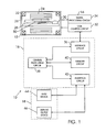
- FIG. 1 is a schematic block diagram of an exemplary magnetic resonance (MR) imaging system suitable for use with the present invention embodiments;
- MR magnetic resonance
- FIG. 2 is a diagrammatic view of a phased array coil assembly for use in the embodiment of FIG. 1 or independently;
- FIG. 3 is a diagrammatic view of one variation of the phased array coil assembly of FIG. 2 ;
- FIG. 4 is a diagrammatic view of another variation of the phased array coil assembly of FIG. 2 ;
- FIG. 5 is a diagrammatic view of one aspect of the signal processing circuit for use in the embodiment of FIG. 1 ;
- FIG. 6 is a diagrammatic view illustrating the connections in one exemplary embodiment of the signal processing circuit of FIG. 5 .
- a magnetic resonance imaging system designated generally by the reference numeral 10 , is illustrated as including a magnet assembly 12 , control and acquisition circuit 14 , system controller circuit 16 , and an operator interface station 18 .
- the magnet assembly 12 includes coil assemblies for selectively generating controlled magnetic fields used to excite gyromagnetic materials spin systems in a subject of interest.
- the magnet assembly 12 includes a primary coil 22 , which will typically include a super conducting magnet coupled to a cryogenic refrigeration system (not shown).
- the primary coil 22 generates a highly uniform magnetic field along a longitudinal axis of the magnet assembly.
- a transmit coil assembly 24 consisting of a series of gradient coils and a transmit RF coil is provided for generating controllable gradient magnetic fields having desired orientations with respect to the subject 30 , and particularly with respect to the region of interest which is illustrated as predetermined area 50 .
- the transmit coil assembly 24 produces fields in response to pulsed signals for selecting an image slice, orienting the image slice, and encoding excited gyromagnetic material spin systems within the slice to produce the desired image.
- a receiving coil assembly which is a phased array coil assembly 26 , according to one aspect of the invention, is provided for detecting emissions from gyromagnetic material spin systems within the predetermined area 50 , during data acquisition phases of operation of the system and is elaborated further in description below.
- a table 28 is positioned within the magnet assembly 12 to support a subject 30 .
- the control and acquisition circuit 14 includes coil control circuit 32 and signal processing circuit 34 .
- the coil control circuit 32 receives pulse sequence descriptions from the system controller 16 , notably through the interface circuit 36 included in the system controller 16 .
- pulse sequence descriptions generally include digitized data defining pulses for exciting the coils the transmit coil assembly 24 during excitation and data acquisition phases of imaging.
- Fields generated by the coils transmit coil assembly 24 excite the spin system within the subject 30 to cause emissions from the material, particularly the region of interest or a predetermined area 50 within the subject 30 .
- Such emissions from the predetermined area 50 are detected by a receiving coil assembly 26 and are filtered, amplified, and transmitted to signal processing circuit 34 .
- Signal processing circuit 34 may perform preliminary processing of the detected signals also described in detail below, and further perform amplification of the signals. Following such processing, the amplified signals are transmitted to the interface circuit 36 for further processing.
- the system controller 16 includes central processing circuit 38 , memory circuit 40 , and interface circuit 42 for communicating with the operator interface station 18 .
- the central processing circuit 38 which will typically include a digital signal processor, a CPU or the like, as well as associated signal processing circuit, commands excitation and data acquisition pulse sequences for the magnet assembly 12 and the control and acquisition circuit 14 through the intermediary of the interface circuit 36 .
- the central processing circuit 38 also processes image data received via the interface circuit 36 , to perform 2D Fourier transforms to convert the acquired data from the time domain to the frequency domain, and to reconstruct the data into a meaningful image.
- the memory circuit 40 serves to save such data, as well as pulse sequence descriptions, configuration parameters, and so forth.
- the interface circuit 42 permits the system controller 16 to receive and transmit configuration parameters, image protocol and command instructions, and so forth.
- the operator interface station 18 includes one or more input devices 44 , along with one or more display or output devices 46 .
- the input device 44 will include a conventional operator keyboard, or other operator input devices for selecting image types, image slice orientations, configuration parameters, and so forth.
- the display/output device 46 will typically include a computer monitor for displaying the operator selections, as well as for viewing scanned and reconstructed images. Such devices may also include printers or other peripherals for reproducing hard copies of the reconstructed images.
- the technique described below may be equally well applied to various alternative configurations of magnetic resonance systems and scanners, including smaller scanners, and scanners incorporating single channel, phased array and similar receiving coil structures. Moreover, the signal combining techniques described below may find application outside of the field of magnetic resonance imaging, and outside of the field of medical imaging in general.
- a magnetic resonance imaging system 10 of FIG. 1 in one aspect comprises a phased array coil assembly 26 as illustrated on the right side in FIG. 2 .
- the coil assembly 26 includes a plurality of coils 52 , which coextensively cover a predetermined area 50 , which is the area of interest with the subject 30 as described with reference to FIG. 1 .
- the plurality of coils 52 are configured such that they detect magnetic resonance signals from a same spatial sensitivity volume enclosed with the predetermined area 50 .
- Each of the plurality of coils 52 comprises a different number of loops 54 over the predetermined area 50 .
- the coils 52 divide the predetermined area 50 into at least three contiguous regions 56 arranged linearly along the predetermined area 50 .
- the predetermined area being divided into four contiguous regions A, B, C, D since in this exemplary embodiment four coils are employed. At least one loop of a respective coil of the plurality of coils 52 is configured to overlap a loop of another respective coil of the plurality of coils 52 to reduce mutual inductance between the plurality of coils 52 .
- the plurality of coils 52 in the phased array coil assembly 26 comprise at least four coils 52 coextensively covering the predetermined area 50 .
- the plurality of coils 52 in the phased array coil assembly 26 , comprise four coils covering the predetermined area 50 as shown on left side in FIG. 2 .
- These coils include, a first coil 58 forming a single loop 60 extending over the predetermined area 50 ; a second coil 62 forming two loops 64 over the predetermined area 50 ; a third coil 66 forming three loops 68 over the predetermined area 50 ; and a fourth coil 70 forming four loops 72 over the predetermined area 50 .
- the four coils 58 , 62 , 66 and 70 overlap, such that the second coil 62 is coextensive with the first coil 58 , the third coil 66 is coextensive with the second coil 62 and the fourth coil 70 is coextensive with the third coil 66 and provide the configuration of the coil assembly 26 on the right side of FIG. 2 and described hereinabove.
- the predetermined area 50 in this example is divided into four contiguous regions 56 , represented by A, B, C, D in FIG. 2 and arranged linearly along the predetermined area 50 .
- the phased array coil assembly 26 comprises a first phased array coil assembly 74 and a second generally similar phased array coil assembly 76 disposed orthogonal to the first phased array coil assembly 74 .
- This arrangement is useful for quadrature detection in MRI.
- These first and second coil assemblies can have several variations.
- the first and second phased array coil assemblies are generally planar.
- the first and second phased array coil assemblies are generally curvacious.
- the phased array coil assembly 26 further comprises a plurality of self similar assemblies 78 disposed to enclose a volume.
- the coil assemblies in these examples comprise the coil configuration as described hereinabove with reference to FIG. 2 .
- each of the plurality of coils 52 is symmetrical about a horizontal and vertical axis with respect to the axis along which the plurality of coils 52 is arranged.
- each of the plurality of coils 52 has a unique spatial phase sensitivity though the volume of spatial sensitivity covered by each coil is substantially the same (volume covering the predetermined area 50 ).
- the plurality of magnetic resonance signals received from the coil assembly 26 will vary in phase with position of the plurality of coils 52 .
- FIG. 1 if A, B, C and D are considered as the regions for MR signal sources, each of these regions has a unique combination of phase shifts associated with it with respect to the four coils 58 , 62 , 66 and 70 . If we depict the anticlockwise rotation as + and clockwise as ⁇ , we can draw a correlation between the coil rotation (phase) and the region of signal source as follows:
- phase array coil assembly 26 as described hereinabove may have other applications and uses in fields different from MR imaging.
- the imaging system 10 also comprises a signal processing circuit 34 coupled to the phased array coil assembly 26 for receiving a plurality of magnetic resonance signals which are detected by the plurality of coils 52 .
- the signal processing circuit 34 is configured to localize these plurality of magnetic resonance signals originating in at least one of the contiguous regions 56 .
- the signal processing circuit 34 in one aspect as shown in FIG. 5 , comprises a plurality of splitters 80 to split a plurality of magnetic resonance signals received from the plurality of coils 52 .
- FIG. 5 illustrates the signals received from four coils 58 , 62 , 66 and 70 .
- Each of the plurality of magnetic resonance signals is split into a first pair of signals 82 with 180 degrees phase shift and each of the first pair of signals 82 is further split into a second pair of signals depicted generally by the reference numeral 84 , with 180 degree phase shift.
- the signal processing circuit 34 further comprises a combiner circuit 86 (including combiners 88 ) to combine the second pair of signals 84 received from the plurality of splitters 80 into combined signal 90 .
- the combiner circuit 86 is configured to yield a selective combination of the plurality of magnetic resonance signals which correlates to an individual contiguous region 56 , represented by A, B, C and D in FIG. 5 .
- FIG. 6 illustrates the respective connections between the splitters 80 and combiners 88 in an exemplary embodiment to yield a combined signal 90 which can be correlated to the individual contiguous regions A, B, C, and D.
- the analog circuit may also employ 90 degree phase shifters in place of 180 degree phase shifters to achieve the desired combination of MR signals.
- Other additional features may also be used, for example each individual coil may be connected to its own receiver and data acquisition system in place of combiners.
- the signal processing circuit 34 in another aspect is configured to convert the plurality of magnetic resonance signals detected by the plurality of coils 52 to a digital form and to perform localization computation to yield a selective combination of the plurality of magnetic resonance signals which correlates to an individual contiguous region 56 .
- the localization computation uses a Hadamard Transform.
- Another aspect of the invention is a method of detecting and transmitting magnetic resonance signals.
- the method includes receiving and transmitting a plurality of magnetic resonance signals using a plurality of coils 52 of a phased array coil assembly 26 , described hereinabove in reference to FIG. 2 , FIG. 3 and FIG. 4 .
- the method also comprises overlapping the loops 54 of the plurality of coils 52 for reducing mutual inductances between the plurality of coils 52 .
- An alternate aspect is a method of using a phased array coil assembly 26 in presence of a gradient field system.
- This method includes receiving a plurality of magnetic resonance signals using a plurality of coils 52 of the phased array coil assembly 26 described in reference with FIG. 2 , FIG. 3 and FIG. 4 , and processing these signals detected by the phased array coil assembly 26 .
- the method for processing the signals comprises localizing the plurality of signals originating in at least one of contiguous regions 56 of the predetermined area 50 being imaged.
- Localizing refers to correlating each of a contiguous regions 56 with a corresponding predetermined combination of a plurality of signals received from each of respective plurality of coils 52 , using phase shifts of the plurality of magnetic resonance signals received from each of respective plurality of coils 52 .
- Processing the magnetic resonance signals comprises using analog circuitry for splitting a plurality of magnetic resonance signals received from the plurality of coils 52 into a first pair of signals 82 with 180 degrees phase shift. Each of the first pair of signals 82 is further split into a second pair of signals 84 with 180 degree phase shift. Processing the magnetic resonance signals further comprises combining the second pair of signals 84 to yield a selective combination of the plurality of magnetic resonance signals which correlates to an individual contiguous region 56 .
- Processing the magnetic resonance signals in another example comprises converting the plurality of magnetic resonance signals detected by the plurality of coils 52 to a digital form and performing localization computation to yield a selective combination of the plurality of magnetic resonance signals which correlates to an individual contiguous region 56 .
- the localization computation uses Hadamard Transform.
- Another aspect of the invention is an image created using the methods described hereinabove.
Landscapes
- Physics & Mathematics (AREA)
- Condensed Matter Physics & Semiconductors (AREA)
- General Physics & Mathematics (AREA)
- Magnetic Resonance Imaging Apparatus (AREA)
Priority Applications (4)
| Application Number | Priority Date | Filing Date | Title |
|---|---|---|---|
| US10/601,352 US6914432B2 (en) | 2003-06-23 | 2003-06-23 | Phased array coil assembly and method and system for employing the same |
| DE102004029574A DE102004029574A1 (de) | 2003-06-23 | 2004-06-18 | Phased-Array-Spulenanordnung und Verfahren und System zu deren Verwendung |
| JP2004183696A JP4587282B2 (ja) | 2003-06-23 | 2004-06-22 | フェーズドアレイ・コイル・アセンブリ、並びにこれを利用するための方法及びシステム |
| NL1026491A NL1026491C2 (nl) | 2003-06-23 | 2004-06-23 | Een phased-array spoelsamenstel en werkwijze en systeem voor het toepassen daarvan. |
Applications Claiming Priority (1)
| Application Number | Priority Date | Filing Date | Title |
|---|---|---|---|
| US10/601,352 US6914432B2 (en) | 2003-06-23 | 2003-06-23 | Phased array coil assembly and method and system for employing the same |
Publications (2)
| Publication Number | Publication Date |
|---|---|
| US20040257079A1 US20040257079A1 (en) | 2004-12-23 |
| US6914432B2 true US6914432B2 (en) | 2005-07-05 |
Family
ID=33517952
Family Applications (1)
| Application Number | Title | Priority Date | Filing Date |
|---|---|---|---|
| US10/601,352 Expired - Lifetime US6914432B2 (en) | 2003-06-23 | 2003-06-23 | Phased array coil assembly and method and system for employing the same |
Country Status (4)
| Country | Link |
|---|---|
| US (1) | US6914432B2 (enExample) |
| JP (1) | JP4587282B2 (enExample) |
| DE (1) | DE102004029574A1 (enExample) |
| NL (1) | NL1026491C2 (enExample) |
Cited By (11)
| Publication number | Priority date | Publication date | Assignee | Title |
|---|---|---|---|---|
| US20050083055A1 (en) * | 2003-10-17 | 2005-04-21 | Dashen Chu | Method and apparatus to improve signal-to-noise ratio without compromising field-of-view for simultaneous MR data acquisition by an array of RF coils of an MR scanner |
| US20050116716A1 (en) * | 2003-10-24 | 2005-06-02 | Pusiol Daniel J. | Sensor assembly and method for the detection of substances by nuclear quadrupolar resonance (NQR) and in presence of environmental interference |
| US20050122110A1 (en) * | 2003-11-19 | 2005-06-09 | Limin Feng | Cervical-thoracic-lumbar spine phased array coil for Magnetic Resonance Imaging |
| US20080042648A1 (en) * | 2003-07-25 | 2008-02-21 | Scott King | Stacked Coil Array for Magnetic Resonance Experiments |
| US20100033177A1 (en) * | 2005-04-25 | 2010-02-11 | Hisaaki Ochi | Inspection Apparatus using Magnetic Resonance and Nuclear Magnetic Resonance Signal Receiver Coil |
| WO2010056911A1 (en) * | 2008-11-12 | 2010-05-20 | Medrad, Inc. | Quadrature endorectal coils and interface devices therefor |
| US20100265020A1 (en) * | 2009-04-17 | 2010-10-21 | General Electric Company | Radio frequency (rf) coil array with double asymmetric saddle coil pairs |
| US20110156705A1 (en) * | 2009-12-30 | 2011-06-30 | General Electric Company | Quadrature and linear rf coil array for mri of human spine and torso |
| US20140132264A1 (en) * | 2012-11-14 | 2014-05-15 | Samsung Electronics Co., Ltd. | Magnetic resonance imaging system and magnetic resonance imaging method |
| US9817090B2 (en) | 2010-07-01 | 2017-11-14 | Bayer Healthcare Llc | Multi-channel endorectal coils and interface devices therefor |
| US20180067180A1 (en) * | 2016-09-06 | 2018-03-08 | Siemens Healthcare Gmbh | Magnetic resonance signal receiving apparatus, reception coil channel selector and magnetic resonance imaging system |
Families Citing this family (9)
| Publication number | Priority date | Publication date | Assignee | Title |
|---|---|---|---|---|
| JP5288693B2 (ja) * | 2005-07-21 | 2013-09-11 | 株式会社東芝 | 磁気共鳴イメージング装置および高周波コイルユニット |
| US7446529B2 (en) * | 2005-07-21 | 2008-11-04 | Kabushiki Kaisha Toshiba | Magnetic resonance imaging apparatus and radio frequency coil unit |
| US7466130B1 (en) * | 2006-02-03 | 2008-12-16 | Fonar Corporation | Phased array shoulder coil |
| JP4901917B2 (ja) * | 2009-06-26 | 2012-03-21 | 中国電力株式会社 | 磁気測定装置、非破壊検査装置および磁気センサの検出コイルの配置方法 |
| DE102010042633B4 (de) * | 2010-10-19 | 2013-02-28 | Siemens Aktiengesellschaft | Antennenschaltung für ein MRT-System |
| US9448297B2 (en) * | 2011-09-07 | 2016-09-20 | Koninklijke Philips N.V. | Mode splitter/combiner for noise figure minimization and control of power in RF coil arrays |
| KR101967243B1 (ko) * | 2012-12-28 | 2019-04-09 | 삼성전자주식회사 | 고속 자기 공명 영상 방법 및 장치 |
| DE102014202716B4 (de) * | 2014-02-14 | 2018-11-29 | Siemens Healthcare Gmbh | Verbesserung des lokalen SAR-Verhaltens von MRT-Sendespulen durch Verwendung orthogonaler Schleifenantennen |
| CN113960681B (zh) * | 2021-08-30 | 2025-04-08 | 苏州太易检测设备有限公司 | 金属检测机的多功能线圈模块及金检机 |
Citations (11)
| Publication number | Priority date | Publication date | Assignee | Title |
|---|---|---|---|---|
| US5370118A (en) * | 1993-12-23 | 1994-12-06 | Medical Advances, Inc. | Opposed loop-pair quadrature NMR coil |
| US5389880A (en) * | 1992-06-30 | 1995-02-14 | Kabushiki Kaisha Toshiba | Magnetic resonance imaging apparatus |
| US5430378A (en) * | 1994-02-22 | 1995-07-04 | Board Of Regents - Univ Of Ne | NMR quadrature detection array |
| US5548218A (en) * | 1995-10-19 | 1996-08-20 | North Shore University Hospital Research Corporation | Flexible RF coils for MRI system |
| US5969525A (en) | 1996-07-01 | 1999-10-19 | U.S. Philips Corporation | MR imaging apparatus |
| US6040697A (en) | 1997-11-26 | 2000-03-21 | Medrad, Inc. | Magnetic resonance imaging receiver/transmitter coils |
| US6150816A (en) * | 1997-02-25 | 2000-11-21 | Advanced Imaging Research, Inc. | Radio-frequency coil array for resonance analysis |
| US6323648B1 (en) * | 1997-11-26 | 2001-11-27 | Medrad, Inc. | Peripheral vascular array |
| US6493572B1 (en) * | 1999-09-30 | 2002-12-10 | Toshiba America Mri, Inc. | Inherently de-coupled sandwiched solenoidal array coil |
| US6534983B1 (en) * | 2000-12-29 | 2003-03-18 | Ge Medical Systems Global Technology Company, Llc | Multi-channel phased array coils having minimum mutual inductance for magnetic resonance systems |
| US6538442B2 (en) | 2000-12-22 | 2003-03-25 | Ge Medical Systems Global Technology Company | MRI system having RF shielding gradient coil structure |
Family Cites Families (11)
| Publication number | Priority date | Publication date | Assignee | Title |
|---|---|---|---|---|
| NL8801018A (nl) * | 1988-04-20 | 1989-11-16 | Philips Nv | Magnetisch resonantie apparaat met ontkoppelde rf-spoelen. |
| JPH0693677B2 (ja) * | 1987-01-12 | 1994-11-16 | 富士通株式会社 | 識別タイミング制御回路 |
| WO1989005115A1 (en) * | 1987-12-07 | 1989-06-15 | General Electric Company | Nuclear magnetic resonance (nmr) imaging with multiple surface coils |
| JP3135592B2 (ja) * | 1990-02-28 | 2001-02-19 | 株式会社東芝 | 磁気共鳴映像装置 |
| JP2680235B2 (ja) * | 1991-11-26 | 1997-11-19 | 株式会社日立製作所 | 核磁気共鳴装置用プローブ |
| JPH05261081A (ja) * | 1992-03-18 | 1993-10-12 | Hitachi Ltd | 核磁気共鳴を用いた検査装置 |
| JPH05305064A (ja) * | 1992-04-30 | 1993-11-19 | Shimadzu Corp | Mri装置の受信コイル |
| JP3340466B2 (ja) * | 1992-08-06 | 2002-11-05 | 株式会社日立製作所 | 核磁気共鳴装置用プローブを用いる受信系 |
| JP3996734B2 (ja) * | 2000-11-20 | 2007-10-24 | 株式会社日立メディコ | 核磁気共鳴を用いた検査装置 |
| JP4443079B2 (ja) * | 2001-09-13 | 2010-03-31 | 株式会社日立メディコ | 磁気共鳴イメージング装置及び磁気共鳴イメージング装置用rf受信コイル |
| JP3825685B2 (ja) * | 2001-11-22 | 2006-09-27 | 株式会社東芝 | 高周波コイルを使用した磁気共鳴映像装置 |
-
2003
- 2003-06-23 US US10/601,352 patent/US6914432B2/en not_active Expired - Lifetime
-
2004
- 2004-06-18 DE DE102004029574A patent/DE102004029574A1/de not_active Withdrawn
- 2004-06-22 JP JP2004183696A patent/JP4587282B2/ja not_active Expired - Fee Related
- 2004-06-23 NL NL1026491A patent/NL1026491C2/nl not_active IP Right Cessation
Patent Citations (11)
| Publication number | Priority date | Publication date | Assignee | Title |
|---|---|---|---|---|
| US5389880A (en) * | 1992-06-30 | 1995-02-14 | Kabushiki Kaisha Toshiba | Magnetic resonance imaging apparatus |
| US5370118A (en) * | 1993-12-23 | 1994-12-06 | Medical Advances, Inc. | Opposed loop-pair quadrature NMR coil |
| US5430378A (en) * | 1994-02-22 | 1995-07-04 | Board Of Regents - Univ Of Ne | NMR quadrature detection array |
| US5548218A (en) * | 1995-10-19 | 1996-08-20 | North Shore University Hospital Research Corporation | Flexible RF coils for MRI system |
| US5969525A (en) | 1996-07-01 | 1999-10-19 | U.S. Philips Corporation | MR imaging apparatus |
| US6150816A (en) * | 1997-02-25 | 2000-11-21 | Advanced Imaging Research, Inc. | Radio-frequency coil array for resonance analysis |
| US6040697A (en) | 1997-11-26 | 2000-03-21 | Medrad, Inc. | Magnetic resonance imaging receiver/transmitter coils |
| US6323648B1 (en) * | 1997-11-26 | 2001-11-27 | Medrad, Inc. | Peripheral vascular array |
| US6493572B1 (en) * | 1999-09-30 | 2002-12-10 | Toshiba America Mri, Inc. | Inherently de-coupled sandwiched solenoidal array coil |
| US6538442B2 (en) | 2000-12-22 | 2003-03-25 | Ge Medical Systems Global Technology Company | MRI system having RF shielding gradient coil structure |
| US6534983B1 (en) * | 2000-12-29 | 2003-03-18 | Ge Medical Systems Global Technology Company, Llc | Multi-channel phased array coils having minimum mutual inductance for magnetic resonance systems |
Cited By (24)
| Publication number | Priority date | Publication date | Assignee | Title |
|---|---|---|---|---|
| US20080042648A1 (en) * | 2003-07-25 | 2008-02-21 | Scott King | Stacked Coil Array for Magnetic Resonance Experiments |
| US7474098B2 (en) * | 2003-07-25 | 2009-01-06 | National Research Council Of Canada | Stacked coil array for magnetic resonance experiments |
| US7109710B2 (en) * | 2003-10-17 | 2006-09-19 | General Electric Company | Method and apparatus to improve signal-to-noise ratio without compromising field-of-view for simultaneous MR data acquisition by an array of RF coils of an MR scanner |
| US20050083055A1 (en) * | 2003-10-17 | 2005-04-21 | Dashen Chu | Method and apparatus to improve signal-to-noise ratio without compromising field-of-view for simultaneous MR data acquisition by an array of RF coils of an MR scanner |
| US20050116716A1 (en) * | 2003-10-24 | 2005-06-02 | Pusiol Daniel J. | Sensor assembly and method for the detection of substances by nuclear quadrupolar resonance (NQR) and in presence of environmental interference |
| US7292033B2 (en) * | 2003-10-24 | 2007-11-06 | Pusiol Daniel J | Sensor assembly and method for the detection of substances by nuclear quadrupolar resonance (NQR) and in presence of environmental interference |
| US20050122110A1 (en) * | 2003-11-19 | 2005-06-09 | Limin Feng | Cervical-thoracic-lumbar spine phased array coil for Magnetic Resonance Imaging |
| US7719276B2 (en) * | 2003-11-19 | 2010-05-18 | General Electric Company | Cervical-thoracic-lumbar spine phased array coil for Magnetic Resonance Imaging |
| US7898255B2 (en) * | 2005-04-25 | 2011-03-01 | Hitachi, Ltd. | Inspection apparatus using magnetic resonance and nuclear magnetic resonance signal receiver coil |
| US20100033177A1 (en) * | 2005-04-25 | 2010-02-11 | Hisaaki Ochi | Inspection Apparatus using Magnetic Resonance and Nuclear Magnetic Resonance Signal Receiver Coil |
| CN102257405B (zh) * | 2008-11-12 | 2015-11-25 | 拜耳医疗保健公司 | 正交直肠内线圈及用于该正交直肠内线圈的接口设备 |
| US20110215807A1 (en) * | 2008-11-12 | 2011-09-08 | Misic George J | Quadrature Endorectal Coils and Interface Devices Therefor |
| US8581590B2 (en) | 2008-11-12 | 2013-11-12 | Medrad, Inc. | Quadrature endorectal coils and interface devices therefor |
| WO2010056911A1 (en) * | 2008-11-12 | 2010-05-20 | Medrad, Inc. | Quadrature endorectal coils and interface devices therefor |
| US8179136B2 (en) * | 2009-04-17 | 2012-05-15 | General Electric Company | Radio frequency (RF) coil array with double asymmetric saddle coil pairs |
| US20100265020A1 (en) * | 2009-04-17 | 2010-10-21 | General Electric Company | Radio frequency (rf) coil array with double asymmetric saddle coil pairs |
| US20110156705A1 (en) * | 2009-12-30 | 2011-06-30 | General Electric Company | Quadrature and linear rf coil array for mri of human spine and torso |
| US8441258B2 (en) | 2009-12-30 | 2013-05-14 | General Electric Company | Quadrature and linear RF coil array for MRI of human spine and torso |
| US10197645B2 (en) | 2010-07-01 | 2019-02-05 | Bayer Healthcare Llc | Multi-channel endorectal coils and interface devices therefor |
| US9817090B2 (en) | 2010-07-01 | 2017-11-14 | Bayer Healthcare Llc | Multi-channel endorectal coils and interface devices therefor |
| US20140132264A1 (en) * | 2012-11-14 | 2014-05-15 | Samsung Electronics Co., Ltd. | Magnetic resonance imaging system and magnetic resonance imaging method |
| US9958523B2 (en) * | 2012-11-14 | 2018-05-01 | Samsung Electronics Co., Ltd. | Magnetic resonance imaging system using sub-volumes and magnetic resonance imaging method using sub-volumes |
| US20180067180A1 (en) * | 2016-09-06 | 2018-03-08 | Siemens Healthcare Gmbh | Magnetic resonance signal receiving apparatus, reception coil channel selector and magnetic resonance imaging system |
| US10641850B2 (en) * | 2016-09-06 | 2020-05-05 | Siemens Healthcare Gmbh | Magnetic resonance signal receiving apparatus, reception coil channel selector and magnetic resonance imaging system |
Also Published As
| Publication number | Publication date |
|---|---|
| US20040257079A1 (en) | 2004-12-23 |
| JP4587282B2 (ja) | 2010-11-24 |
| JP2005013726A (ja) | 2005-01-20 |
| NL1026491A1 (nl) | 2004-12-28 |
| DE102004029574A1 (de) | 2005-01-13 |
| NL1026491C2 (nl) | 2006-08-08 |
Similar Documents
| Publication | Publication Date | Title |
|---|---|---|
| US6914432B2 (en) | Phased array coil assembly and method and system for employing the same | |
| JP5260819B2 (ja) | 並列式mriを用いた撮像を高速化させるための方法及びシステム | |
| US7009396B2 (en) | Method and system for extended volume imaging using MRI with parallel reception | |
| US6377044B1 (en) | Multi-mode receiver coils for MRI | |
| US9396562B2 (en) | MRI reconstruction with incoherent sampling and redundant haar wavelets | |
| US8581589B2 (en) | System and method for variable mode-mixing in magnetic resonance imaging | |
| US7221161B2 (en) | Coil arrays for parallel imaging in magnetic resonance imaging | |
| EP2411829B1 (en) | Mr imaging using parallel signal acquisition | |
| EP2992351B1 (en) | Dixon-type water/fat separation mri using high-snr in-phase image and lower-snr at least partially out-of-phase image | |
| US5759152A (en) | Phase-aligned NMR surface coil image reconstruction | |
| EP0616229B1 (en) | Magnetic resonance imaging apparatus and methods | |
| US6377836B1 (en) | RF coil array for vertical field MRI | |
| EP0695951A1 (en) | Magnetic resonance methods and apparatus | |
| US7498809B2 (en) | Magnetic resonance imaging device with multiple RF coils applying half-pulse waveforms for selective excitation of a local region | |
| CN103782184A (zh) | Rf阵列线圈/天线阻抗的动态修改 | |
| CN100416294C (zh) | 磁共振成像设备及方法 | |
| JP2006507071A (ja) | 磁気共鳴方法 | |
| JP3992934B2 (ja) | 磁気共鳴イメージング装置および方法 | |
| WO2000072050A9 (en) | Method and apparatus for parallel data acquisition from a mri coil array | |
| US7235973B2 (en) | Phased array coils utilizing selectable quadrature combination | |
| EP1685419A1 (en) | Parallel mr imaging method | |
| US8587309B2 (en) | Phase-dependent magnetic-resonance imaging with multiple coils | |
| JP2005118567A (ja) | Mrスキャナのrfコイルのアレイによる同時mrデータ収集の撮影領域を損なうことなく信号対雑音比を改善する方法及び装置 | |
| JP2004298212A (ja) | Rfコイルおよび磁気共鳴撮影装置 |
Legal Events
| Date | Code | Title | Description |
|---|---|---|---|
| AS | Assignment |
Owner name: GENERAL ELECTRIC COMPANY, NEW YORK Free format text: ASSIGNMENT OF ASSIGNORS INTEREST;ASSIGNORS:DUMOULIN, CHARLES;WATKINS, RONALD;GIAQUINTO, RANDY;REEL/FRAME:014228/0751;SIGNING DATES FROM 20030618 TO 20030623 |
|
| FEPP | Fee payment procedure |
Free format text: PAYOR NUMBER ASSIGNED (ORIGINAL EVENT CODE: ASPN); ENTITY STATUS OF PATENT OWNER: LARGE ENTITY |
|
| STCF | Information on status: patent grant |
Free format text: PATENTED CASE |
|
| FPAY | Fee payment |
Year of fee payment: 4 |
|
| FPAY | Fee payment |
Year of fee payment: 8 |
|
| FPAY | Fee payment |
Year of fee payment: 12 |