US6901218B2 - Photometer, image sensing device, photometric method, program and recording medium - Google Patents
Photometer, image sensing device, photometric method, program and recording medium Download PDFInfo
- Publication number
- US6901218B2 US6901218B2 US10/665,756 US66575603A US6901218B2 US 6901218 B2 US6901218 B2 US 6901218B2 US 66575603 A US66575603 A US 66575603A US 6901218 B2 US6901218 B2 US 6901218B2
- Authority
- US
- United States
- Prior art keywords
- dimensional data
- value
- calculating
- brightness value
- screen
- Prior art date
- Legal status (The legal status is an assumption and is not a legal conclusion. Google has not performed a legal analysis and makes no representation as to the accuracy of the status listed.)
- Expired - Lifetime
Links
- 238000000034 method Methods 0.000 title claims description 21
- 238000006243 chemical reaction Methods 0.000 claims description 14
- 238000012545 processing Methods 0.000 claims description 4
- 238000012935 Averaging Methods 0.000 claims 2
- 238000005375 photometry Methods 0.000 abstract 1
- 238000012937 correction Methods 0.000 description 14
- 238000001514 detection method Methods 0.000 description 11
- 238000004364 calculation method Methods 0.000 description 8
- 238000004891 communication Methods 0.000 description 7
- 230000003287 optical effect Effects 0.000 description 5
- 238000009825 accumulation Methods 0.000 description 4
- 238000007796 conventional method Methods 0.000 description 2
- 238000010586 diagram Methods 0.000 description 2
- 230000007246 mechanism Effects 0.000 description 2
- 230000002093 peripheral effect Effects 0.000 description 2
- 230000001131 transforming effect Effects 0.000 description 2
- 229930091051 Arenine Natural products 0.000 description 1
- XUIMIQQOPSSXEZ-UHFFFAOYSA-N Silicon Chemical compound [Si] XUIMIQQOPSSXEZ-UHFFFAOYSA-N 0.000 description 1
- 230000003321 amplification Effects 0.000 description 1
- 230000015572 biosynthetic process Effects 0.000 description 1
- 230000008859 change Effects 0.000 description 1
- 230000001186 cumulative effect Effects 0.000 description 1
- 230000000694 effects Effects 0.000 description 1
- 238000005286 illumination Methods 0.000 description 1
- 238000003384 imaging method Methods 0.000 description 1
- 239000004973 liquid crystal related substance Substances 0.000 description 1
- 238000012986 modification Methods 0.000 description 1
- 230000004048 modification Effects 0.000 description 1
- 238000003199 nucleic acid amplification method Methods 0.000 description 1
- 230000011514 reflex Effects 0.000 description 1
- 229910052710 silicon Inorganic materials 0.000 description 1
- 239000010703 silicon Substances 0.000 description 1
- 230000009466 transformation Effects 0.000 description 1
Images




Classifications
-
- G—PHYSICS
- G03—PHOTOGRAPHY; CINEMATOGRAPHY; ANALOGOUS TECHNIQUES USING WAVES OTHER THAN OPTICAL WAVES; ELECTROGRAPHY; HOLOGRAPHY
- G03B—APPARATUS OR ARRANGEMENTS FOR TAKING PHOTOGRAPHS OR FOR PROJECTING OR VIEWING THEM; APPARATUS OR ARRANGEMENTS EMPLOYING ANALOGOUS TECHNIQUES USING WAVES OTHER THAN OPTICAL WAVES; ACCESSORIES THEREFOR
- G03B7/00—Control of exposure by setting shutters, diaphragms or filters, separately or conjointly
- G03B7/08—Control effected solely on the basis of the response, to the intensity of the light received by the camera, of a built-in light-sensitive device
Definitions
- the present invention relates to a photometer useful for an image sensing device such as a still camera or a video camera, the image sensing device, a photometric method, a program and a recording medium.
- a technique for correct exposure has been put to practical use in which a photographing screen is divided into plural areas to acquire a plurality of brightness information for the field, and it is discriminated whether or not a back light is present on the basis of the plurality of brightness information in accordance with a predetermined algorithm.
- Japanese Patent Laid-Open No. 6-225205 such conventional technique was described.
- the photographing screen is divided into a plurality of blocks, and the photometric value data is obtained from cumulative data for each block and the maximum value within the screen.
- an iris control is made by changing a photometric reference value depending on whether a central part of the screen is a back light state or a follow light state, enabling the correct iris operation to be made for photographing under the back light condition.
- a video camera is taken as an example, in which the term of iris operation is used, but has the same meaning as the exposure control for the still camera to make the correct exposure for an image sensing element or film.
- a typical example of the condition called back light is a situation where the brightness is low in a central part and a central lower part of the screen and high in other upper part and left and right parts of the screen, as shown in FIG. 3 of Japanese Patent Laid-Open No. 6-225205.
- the back light situation is the above situation where the brightness is low in a central part and a central lower part of the screen and high in other upper part and left and right parts of the screen.
- FIG. 10A shows one example of photographing composition, in which reference numeral 71 is a portrait area for the principal subject, 72 is a sky area, 73 is a ground area, 74 is a mountain area, and 75 to 77 are the tree areas.
- reference numeral 71 is a portrait area for the principal subject
- 72 is a sky area
- 73 is a ground area
- 74 is a mountain area
- 75 to 77 are the tree areas.
- the sky area 72 among these areas has a high brightness
- other areas, particularly the portrait area 71 and the tree areas 75 to 77 have the low brightness.
- an upper-part of the screen is only light, and the left and right parts of the principal subject are dark.
- the present invention has been achieved in the background as described above, and it is an object of the invention to provide a photometer to make the exposure control for an image sensing device, the photometer comprising a photometric sensor being two-dimensionally divided into plural areas within a screen, in which one-dimensional data is calculated from the outputs of the photometric sensor, the maximum value of the one-dimensional data is detected, an exposure compensation value is calculated in accordance with the detected maximum value of the one-dimensional data, an average brightness value of the subject is calculated over the screen, and the exposure compensation value and the average brightness value are added to acquire a correct brightness value of the subject.
- the back light In a back light scene where only a part of the screen is light, the back light is adequately detected to make a correct exposure, thereby realizing the exposure control for the camera.
- FIG. 1 is a cross-sectional view showing an arrangement of optical members for a camera and an interchangeable lens according to the present invention
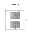
- FIG. 2 is a view showing a constitutional example of a focus detecting sensor
- FIG. 3 is a view showing a constitutional example of a photometric sensor
- FIG. 4 is a view exemplifying focus detected positions on a photographing screen
- FIG. 5 is a block diagram showing a constitutional example of the electrical circuits for the camera and the interchangeable lens
- FIG. 6 is a flowchart showing the operation of control means for the camera
- FIG. 7 is a flowchart showing the operation of the control means for the camera in conjunction with FIG. 6 ;
- FIG. 8 is a view showing the relationship between two-dimensional brightness data and one-dimensional projection data
- FIG. 9 is an explanatory graph representing the high brightness correction value
- FIGS. 10A and 10B are views showing a photographing screen and a table exemplifying the brightness data
- FIG. 11 is an explanatory graph representing the flash producing condition.
- FIGS. 12A and 12B are views showing a constitutional example of a photometric sensor according to a second embodiment of the invention.
- FIG. 1 is a cross-sectional view showing an arrangement of optical members for a camera according to the present invention.
- the camera is a so-called single-lens reflex type in which the lens is interchangeable, in which reference numeral 10 is a camera main body and 30 is an interchangeable lens.
- reference numeral 11 is an optical axis of a photographing lens
- 12 is a film face
- 13 is a semitransparent main mirror
- 14 is a first reflecting mirror, in which the main mirror 13 and the first reflecting mirror 14 are sprung up together at the time of photographing.
- Reference numeral 15 is a paraxial image formation face conjugate with the film face 12 by the first reflecting mirror 14
- 16 is a second reflecting mirror
- 17 is an infrared cut filter
- 18 is a diaphragm having two openings
- 19 is a secondary imaging lens
- 20 is a focus detecting sensor.
- the focus detecting sensor 20 is a photoelectric conversion element of area storage type such as a CMOS or a CCD, which comprises two pairs of photo sensors 20 A and 20 B having multiply divided areas, corresponding to two openings of the diaphragm 18 , as shown in FIG. 2 .
- the peripheral circuits for signal storage and signal processing are composed of integrated circuits on the same chip.
- a mechanism from the first reflecting mirror 14 to the focus detecting sensor 20 enables the focus detection to be made based on an image drift at any position within the photographing screen, as described in detail in Japanese Patent Laid-Open No. 9-184965.
- Reference numeral 21 is a focusing screen having diffusivity
- 22 is a pentaprism
- 23 is an ocular lens
- 24 is a third reflecting mirror
- 25 is a condensing lens
- 26 is a photometric sensor for acquiring the information regarding the brightness of the subject.
- the photometric sensor 26 consists of a photoelectric conversion element such as a silicon photodiode, in which a plurality of photo sensors are arranged like a lattice to contain the entire photographing screen in the field of view, as shown in FIG. 3 .
- the 35 divided photocells are referred to as PD 11 to PD 57 .
- the peripheral circuits for signal amplification and signal processing are composed of integrated circuits on the same chip.
- FIG. 4 is a view showing the positional relation of correspondence between the focus detected position by focus detecting means such as the focus detecting sensor 20 and the 35 divided photo sensors of the photometric sensor 26 within the photographing screen.
- focus detected positions S 01 to S 23 within the photographing screen, in which the focus detected position S 01 corresponds to the photocell PD 23 of the photometric sensor 26 to detect the focal point.
- the focus detecting position S 02 corresponds to the photocell PD 24 of the photometric sensor 26 to detect the focal point
- the focus detecting position S 03 corresponds to the photocell PD 25 of the photometric sensor 26 to detect the focal point
- the focus detecting position S 23 corresponds to the photocell PD 45 of the photometric sensor 26 to detect the focal point, as shown in FIG. 4 .
- Reference numeral 27 is a mount portion for mounting the photographing lens, and 28 is a contact portion for communicating the information with the photographing lens.
- reference numeral 31 is a diaphragm, 32 is a contact portion for communicating the information with the camera main body, 33 is a mount portion to be mounted on the camera, and 34 to 36 are optical lenses making up the photographing lens.
- FIG. 5 is a block diagram showing a constitutional example of the electrical circuits for the camera main body 10 and its interchangeable lens 30 according to the invention.
- reference numeral 41 is control means with a one-chip microcomputer comprising ALU, ROM, RAM, an A/D converter and a serial communication port internally to make the overall control of the camera mechanism. A specific sequence of the control means 41 will be described later.
- the focus detecting sensor 20 and the photometric sensor 26 are the same as those shown in FIG. 1 .
- the output signals from the focus detecting sensor 20 and the photometric sensor 26 are connected to an input terminal of the A/D converter in the control means 41 .
- Reference numeral 42 is a shutter connected to an output terminal of the control means 41 and controlled.
- Reference numeral 43 is a first motor driver connected to the output terminal of the control means 41 and controlled, in which the first motor driver drives a first motor 44 for feeding the film or moving the main mirror 13 .
- Reference numeral 45 is a sensor for detecting the attitude of the camera, its output signal being connected to the input terminal of the control means 41 .
- the control means 41 inputs the information of an attitude detecting sensor 45 to acquire the information as to whether the camera is held in the transverse or longitudinal position for photographing.
- Reference numeral 46 is an AF light source for emitting an infrared ray when the focus detection is made by the focusing sensor 20 under the condition of low illumination, in which the AF light source emits light in accordance with an output signal of the control means 41 .
- Reference numeral 47 is flash means for producing the flash at the photographing time when the brightness of the subject is insufficient, in which flash means is excited in accordance with an output signal of the control means 41 .
- Reference numeral 48 is a display for displaying the number of photographing sheets, the date and time, and the photographing information.
- the display is composed of a liquid crystal panel, and each indicator lamp is lighted in accordance with an output signal of the control means 41 .
- Reference numeral 49 is various kinds of switches, including a release button.
- Reference numeral 28 is a contact portion as shown in FIG. 1 to which an input/output signal of the serial communication port in the control means 41 is connected.
- reference numeral 51 is lens control means with a one-chip microcomputer comprising ALU, ROM, RAM and the serial communication port internally.
- Reference numeral 52 is a second motor driver for driving a second motor 53 , which is connected to an output terminal of the lens control means 51 and controlled to make the focus adjustment.
- Reference numeral 54 is a third motor driver for driving a third motor 55 , which is connected to the output terminal of the lens control means 51 and controlled to regulate the diaphragm 31 , as shown in FIG. 1 .
- Reference numeral 56 is a distance encoder for acquiring the information regarding an extension amount of focusing lens, namely a subject distance, the distance encoder being connected to an input terminal of the lens control means 51 .
- Reference numeral 57 is a zoom encoder for acquiring the focal length information in photographing, when the interchangeable lens 30 is zoom lens, the zoom encoder being connected to the input terminal of the lens control means 51 .
- Reference numeral 32 is the contact portion as shown in FIG. 1 , to which an input/output signal of the lens control means 51 at the serial communication port is connected.
- the contact portions 28 and 32 are connected so that the lens control means 51 is enabled to make data communication with the control means 41 of the camera main body.
- the optical information intrinsic to the lens that is necessary for the control means 41 of the camera main body to make the focus detection or exposure operation, and the information regarding the subject distance or focal length based on the distance encoder 56 or the zoom encoder 57 are passed through the data communication from the lens control means 51 to the control means 41 of the camera main body.
- the focusing information or diaphragm information that is obtained as a result of the focus detection or exposure operation made by the control means 41 of the camera main body is output through the data communication from the control means 41 of the camera main body to the lens control means 51 , so that the lens control means 51 may control the second motor driver 52 in accordance with the focusing information and control the third motor driver 54 in accordance with the diaphragm information.
- control means 41 in the camera main body will be described below. If a power switch, not shown, is turned on, the control means 41 becomes operable. If a first stroke switch of the release button, not shown, is turned on, the operation starts at step ( 101 ) in FIG. 6 .
- the calculation data range is changed depending on the focus detecting position information in the following way. Since the focus detecting position is fundamentally considered to be the position of the principal subject, the exposure operation is made by weighting the 5 ⁇ 5 area including the position of principal subject as the principal photometric area with higher value or feature.
- Y 1 ( ED 11 + ED 12 + ED 13 + ED 14 + ED 15 )+5
- Y 2 ( ED 21 + ED 22 + ED 23 + ED 24 + ED 25 )+5
- Y 3 ( ED 31 + ED 32 + ED 33 + ED 34 + ED 35 )+5
- Y 4 ( ED 41 + ED 42 + ED 43 + ED 44 + ED 45 )+5
- Y 5 ( ED 51 + ED 52 + ED 53 + ED 54 + ED 55 )+5
- Y 1 ( ED 12 + ED 13 + ED 14 + ED 15 +ED 16 )+5
- Y 2 ( ED 22 + ED 23 + ED 24 + ED 25 + ED 26 )+5
- Y 3 ( ED 32 + ED 33 + ED 34 + ED 35 + ED 36 )+5
- Y 4 ( ED 42 + ED 43 + ED 44 + ED 45 + ED 46 )+5
- Y 5 ( ED 52 + ED 53 + ED 54 + ED 55 + ED 56 )+5
- Y 1 ( ED 13 + ED 14 + ED 15 + ED 16 + ED 17 )+5
- Y 2 ( ED 23 + ED 24 + ED 25 + ED 26 + ED 27 )+5
- Y 3 ( ED 33 + ED 34 + ED 35 + ED 36 + ED 37 )+5
- Y 4 ( ED 43 + ED 44 + ED 45 + ED 46 + ED 47 )+5
- Y 5 ( ED 53 + ED 54 + ED 55 + ED 56 + ED 57 )+5
- the condition includes when the focus detecting position is S 01 , S 11 or S 21 in FIG. 4 and the maximum value among the projection data is X 6 or X 7 , when the focus detecting position is S 02 , S 12 or 522 in FIG. 4 and the maximum value among the projection data is X 1 or X 7 , or when the focus detecting position is S 03 , S 13 or S 23 in FIG. 4 and the maximum value among the projection data is X 1 or X 2 .
- the maximum value detecting area has a lower weight, when the average brightness value Ea is calculated at step ( 153 ), it is necessary that the high brightness correction value ⁇ is reduced.
- FIGS. 10A and 10B The brightness information ED 11 to ED 57 corresponding to a scene of FIG. 10 A and the calculated projection data Y 1 to Y 5 and X 1 to X 7 are represented as numerical values in FIG. 10B in accordance with the array of FIG. 8 .
- the gradient value ⁇ E of brightness is calculated on the basis of the focus detecting position information.
- the focus detecting position is S 01 , S 11 or S 21 in FIG. 4
- ⁇ E ⁇ ( X 1 + X 2 )/2 ⁇ ( X 4 + X 5 )/2 ⁇ /3
- ⁇ E ⁇ ( X 3 + X 4 )/2 ⁇ ( X 6 + X 7 )/2 ⁇ /3
- the gradient value ⁇ E of brightness is calculated on the basis of the focus detecting position information in accordance with the following expression.
- ⁇ E ⁇ ( X 4 + X 5 )/2 ⁇ ( X 1 +X 2 )/2 ⁇ /3
- ⁇ E ⁇ ( X 5 + X 6 )/2 ⁇ ( X 2 + X 3 )/2 ⁇ /3
- the meaning of the calculated gradient value ⁇ E of brightness is the numerical value simply indicating the average change rate of brightness in the top and bottom direction for each row (column) in the 5 ⁇ 5 area near the focus detecting position within the photographing screen.
- Es is equal to ED 23 (when the focus detecting position is S 01 ), ED 24 (when the focus detecting position is S 02 ), ED 25 (when the focus detecting position is S 03 ), ED 33 (when the focus detecting position is S 11 ), ED 34 (when the focus detecting position is S 12 ), ED 35 (when the focus detecting position is S 13 ), ED 43 (when the focus detecting position is S 21 ), ED 44 (when the focus detecting position is S 22 ), or ED 45 (when the focus detecting position is S 23 ).
- the flash means 47 may not be employed, even if the first or second condition is satisfied. Also, when the camera is not in a photographing mode for automatically employing the flash means, it is unnecessary to perform this step. When it is discriminated that the flash means 47 should be employed to photograph the scene, the flash means 47 is prepared to produce the flash.
- the optimal exposure control factors namely the shutter speed and the stop value, are decided on the basis of the subject brightness value Ee and the presence or absence of employing the flash means 47 that is discriminated at step ( 157 ).
- the photometric sensor is divided into 5 ⁇ 7 or 35 photocells, and the number of focus detecting positions is 9 , the invention is not limited to this case.
- the photocells of the photometric sensor 26 are arranged in the two-dimensional array of m rows ⁇ n columns.
- a photometer having the same back light detecting effect can be realized as follows.
- FIG. 12A is a view showing the photocells of a second photometric sensor 626 , instead of the photometric sensor 26 in the first embodiment.
- the second photometric sensor 626 are divided into 29 photocells P 01 to P 45 arranged like a swage block, each photocell having a hexagonal shape.
- FIG. 12B is a view showing three focus detecting positions S 31 to S 33 in the second embodiment, in which the focus detecting position S 31 corresponds to the photocell P 23 of the photometric sensor 626 to make the focus detection, the focus detecting position S 32 corresponds to the photocell P 24 of the photometric sensor 626 to make the focus detection, and the focus detecting position S 33 corresponds to the photocell P 25 of the photometric sensor 626 to make the focus detection.
- Other constitution is not different from the first embodiment as shown in FIG. 1 or 5 .
- the overall flowchart as shown in FIG. 6 in the first embodiment is employed in the first embodiment.
- a part of the exposure operation as shown in FIG. 7 is different from the first embodiment, and will be described below.
- X 1 ( E 21 ⁇ 2+ E 11 + E 31 )+4
- X 2 ( E 01 ⁇ 2+ E 22 ⁇ 2+ E 41 ⁇ 2+ E 11 + E 12 + E 31 + E 32 )+10
- X 3 ( E 02 ⁇ 2+ E 23 ⁇ 2+ E 42 ⁇ 2+ E 12 + E 13 + E 32 + E 33 )+10
- X 4 ( E 03 ⁇ 2+ E 24 ⁇ 2+ E 43 ⁇ 2+ E 13 + E 14 + E 33 + E 34 )+10
- X 5 ( E 04 ⁇ 2+ E 25 ⁇ 2+ E 44 ⁇ 2+ E 14 + E 15 + E 34 + E 35 )+10
- X 6 ( E 05 ⁇ 2+ E 26 ⁇ 2+ E 45 ⁇ 2+ E 15 + E 16 + E 35 + E 36 )+10
- X 7 ( E 27 ⁇ 2+ E 16
- the calculation data range is changed depending on the focus detecting position information in the following way. Since the focus detecting position is fundamentally considered to be the position of the principal subject, the exposure operation is made by weighting the 5 ⁇ 5 area including the position of principal subject as the principal photometric area with higher value or feature.
- Y 1 ( E 01 + E 02 + E 03 + E 04 + E 05 )+5
- Y 2 ( E 11 + E 12 + E 13 + E 14 + E 15 )+5
- Y 3 ( E 21 + E 22 + E 23 + E 24 + E 25 )+5
- Y 4 (E 31 +E 32 +E 33 +E 34 +E 35 )+5
- Y 5 ( E 41 + E 42 + E 43 + E 44 + E 45 )+5
- Y 1 ( E 01 + E 02 + E 03 + E 04 + E 05 )+5
- Y 2 ( E 11 ⁇ 0.5 +E 12 + E 13 + E 14 + E 15 + E 16 ⁇ 0.5)+5
- Y 3 ( E 22 + E 23 + E 24 + E 25 + E 26 )+5
- Y 4 ( E 31 ⁇ 0.5 +E 32 + E 33 + E 34 + E 35 + E 36 ⁇ 0.5)+5
- Y 5 ( E 41 + E 42 + E 43 + E 44 + E 45 )+5
- Y 1 ( E 01 + E 02 + E 03 + E 04 + E 05 )+5
- Y 2 ( E 12 + E 13 + E 14 + E 15 + E 16 )+5
- Y 3 ( E 23 + E 24 + E 25 + E 26 + E 27 )+5
- Y 4 ( E 32 + E 33 + E 34 + E 35 + E 36 )+5
- Y 5 ( E 41 + E 42 + E 43 + E 44 + E 45 )+5
- the condition includes when the focus detecting position is S 31 in FIG. 12 B and the maximum value among the one-dimensional data is X 6 or X 7 , when the focus detecting position is S 32 in FIG. 12 B and the maximum value among the one-dimensional data is X 1 or X 7 , or when the focus detecting position is S 33 in FIG. 12 B and the maximum value among the one-dimensional data is X 1 or X 2 .
- the maximum value detecting area has the lower weight in calculating the average brightness value Ea at step ( 153 ) as in the first embodiment, the high brightness correction value ⁇ is reduced.
- ⁇ E ⁇ ( Y 1 + Y 2 )/2 ⁇ ( Y 4 + Y 5 )/2 ⁇ /3
- the gradient value ⁇ E of brightness is calculated on the basis of the focus detecting position information.
- the gradient value ⁇ E of brightness is calculated on the basis of the focus detecting position information in accordance with the following expression.
- Es is equal to E 23 (when the focus detecting position is S 31 ), E 24 (when the focus detecting position is S 32 ), or E 25 (when the focus detecting position is S 33 ).
- the flash means 47 may not be employed, even if the first or second condition is satisfied. Also, when the camera is not in the photographing mode for automatically employing the flash means, it is unnecessary to perform this step. When it is discriminated that the flash means 47 should be employed to photograph the scene, the flash means 47 is prepared to produce the flash.
- this invention is also applicable to a so-called video camera or electronic still camera in which the photoelectric conversion element such as CCD converts the image information in the field into electric signal which is then output or processed.
- the photometric sensor may not be specifically provided, in which the brightness information of the subject is acquired from the photoelectric conversion element for image pickup, and the acquired brightness information is converted into one-dimensional brightness data to discriminate the back light.
Landscapes
- Physics & Mathematics (AREA)
- General Physics & Mathematics (AREA)
- Exposure Control For Cameras (AREA)
- Automatic Focus Adjustment (AREA)
- Photometry And Measurement Of Optical Pulse Characteristics (AREA)
- Studio Devices (AREA)
- Focusing (AREA)
Applications Claiming Priority (2)
| Application Number | Priority Date | Filing Date | Title |
|---|---|---|---|
| JP2002-273252(PAT.) | 2002-09-19 | ||
| JP2002273252A JP3958164B2 (ja) | 2002-09-19 | 2002-09-19 | カメラの測光装置 |
Publications (2)
| Publication Number | Publication Date |
|---|---|
| US20040190890A1 US20040190890A1 (en) | 2004-09-30 |
| US6901218B2 true US6901218B2 (en) | 2005-05-31 |
Family
ID=32270049
Family Applications (1)
| Application Number | Title | Priority Date | Filing Date |
|---|---|---|---|
| US10/665,756 Expired - Lifetime US6901218B2 (en) | 2002-09-19 | 2003-09-19 | Photometer, image sensing device, photometric method, program and recording medium |
Country Status (2)
| Country | Link |
|---|---|
| US (1) | US6901218B2 (https=) |
| JP (1) | JP3958164B2 (https=) |
Cited By (1)
| Publication number | Priority date | Publication date | Assignee | Title |
|---|---|---|---|---|
| US20140055666A1 (en) * | 2012-08-24 | 2014-02-27 | Canon Kabushiki Kaisha | Image capture apparatus and method of controlling the same |
Families Citing this family (9)
| Publication number | Priority date | Publication date | Assignee | Title |
|---|---|---|---|---|
| KR100557219B1 (ko) * | 2004-07-06 | 2006-03-07 | 삼성전자주식회사 | 자동 노출 보정 방법 및 보정 장치 |
| KR20090098197A (ko) * | 2008-03-13 | 2009-09-17 | 삼성디지털이미징 주식회사 | 플래시 발광량 조절가능한 디지털 촬영 장치, 이의 제어방법 및 상기 방법을 실행하기 위한 프로그램을 기록한기록매체 |
| US7978967B2 (en) * | 2008-05-16 | 2011-07-12 | Panasonic Corporation | Camera body, interchangeable lens, and imaging apparatus |
| JP5428568B2 (ja) | 2009-06-23 | 2014-02-26 | リコーイメージング株式会社 | 露出制御ユニットおよび撮影装置 |
| JP2011223378A (ja) * | 2010-04-12 | 2011-11-04 | Sanyo Electric Co Ltd | 電子カメラ |
| US8786847B2 (en) * | 2011-01-12 | 2014-07-22 | Underwriters Laboratories, Inc. | Light measuring meter apparatus |
| JP2014079392A (ja) * | 2012-10-17 | 2014-05-08 | Canon Inc | 眼科撮影装置 |
| JP6388391B2 (ja) * | 2014-09-05 | 2018-09-12 | キヤノン株式会社 | 逆光判別装置、その制御方法、および制御プログラム、並びに撮像装置 |
| CN108259775B (zh) * | 2018-04-09 | 2021-01-22 | 京东方科技集团股份有限公司 | 一种成像方法、成像装置及后视镜 |
Citations (6)
| Publication number | Priority date | Publication date | Assignee | Title |
|---|---|---|---|---|
| JPH06225205A (ja) | 1993-01-22 | 1994-08-12 | Sharp Corp | ビデオカメラ |
| US5450163A (en) * | 1992-09-25 | 1995-09-12 | Nikon Corporation | Photometric device for camera |
| JPH09184965A (ja) | 1995-12-28 | 1997-07-15 | Canon Inc | 焦点検出装置及びそれを用いた光学機器 |
| US5703644A (en) * | 1992-05-21 | 1997-12-30 | Matsushita Electric Industrial Co., Ltd. | Automatic exposure control apparatus |
| JPH11190816A (ja) | 1997-12-25 | 1999-07-13 | Canon Inc | 光学装置及び測距点選択方法 |
| JP2002296635A (ja) | 2001-03-30 | 2002-10-09 | Canon Inc | カメラ |
-
2002
- 2002-09-19 JP JP2002273252A patent/JP3958164B2/ja not_active Expired - Fee Related
-
2003
- 2003-09-19 US US10/665,756 patent/US6901218B2/en not_active Expired - Lifetime
Patent Citations (6)
| Publication number | Priority date | Publication date | Assignee | Title |
|---|---|---|---|---|
| US5703644A (en) * | 1992-05-21 | 1997-12-30 | Matsushita Electric Industrial Co., Ltd. | Automatic exposure control apparatus |
| US5450163A (en) * | 1992-09-25 | 1995-09-12 | Nikon Corporation | Photometric device for camera |
| JPH06225205A (ja) | 1993-01-22 | 1994-08-12 | Sharp Corp | ビデオカメラ |
| JPH09184965A (ja) | 1995-12-28 | 1997-07-15 | Canon Inc | 焦点検出装置及びそれを用いた光学機器 |
| JPH11190816A (ja) | 1997-12-25 | 1999-07-13 | Canon Inc | 光学装置及び測距点選択方法 |
| JP2002296635A (ja) | 2001-03-30 | 2002-10-09 | Canon Inc | カメラ |
Non-Patent Citations (5)
| Title |
|---|
| English Abstract for JPA 06-225205. |
| English Abstract for JPA 09-184965. |
| English Abstract for JPA 11-190816. |
| English Abstract for JPA 2002-296635. |
| Partial Translation of JPA 2002-296635. |
Cited By (2)
| Publication number | Priority date | Publication date | Assignee | Title |
|---|---|---|---|---|
| US20140055666A1 (en) * | 2012-08-24 | 2014-02-27 | Canon Kabushiki Kaisha | Image capture apparatus and method of controlling the same |
| US9392181B2 (en) * | 2012-08-24 | 2016-07-12 | Canon Kabushiki Kaisha | Image capture apparatus and method of controlling the same |
Also Published As
| Publication number | Publication date |
|---|---|
| JP2004109605A (ja) | 2004-04-08 |
| US20040190890A1 (en) | 2004-09-30 |
| JP3958164B2 (ja) | 2007-08-15 |
Similar Documents
| Publication | Publication Date | Title |
|---|---|---|
| EP3110135B1 (en) | Image pickup apparatus | |
| JP5020651B2 (ja) | 撮像装置及び撮像システム | |
| EP1975695B1 (en) | Focus detection device, focusing state detection method and imaging apparatus | |
| US8730374B2 (en) | Focus detection apparatus | |
| JPH07504279A (ja) | 測光および距離測定素子の複合化アレー | |
| JP4709247B2 (ja) | 焦点検出装置及び制御方法 | |
| US6901218B2 (en) | Photometer, image sensing device, photometric method, program and recording medium | |
| JP3597657B2 (ja) | カメラの測距装置 | |
| CN101571660B (zh) | 数码相机及其自动聚焦方法 | |
| KR100388918B1 (ko) | 카메라의측광영역이가변되는휘도측광장치및그제어방법 | |
| JP2006072084A (ja) | 自動焦点検出装置およびカメラシステム | |
| JP2015087494A (ja) | 撮像装置 | |
| JP4950634B2 (ja) | 撮像装置及び撮像システム | |
| JP4859194B2 (ja) | 撮像装置及びその制御方法及びプログラム及び記憶媒体 | |
| JP2004120582A (ja) | カメラ | |
| JP2014098768A (ja) | 撮像装置及び露出制御方法 | |
| JP5417032B2 (ja) | カメラの測光装置 | |
| JP4928236B2 (ja) | 撮像装置及び撮像システム | |
| JP2006014034A (ja) | 撮像装置および撮像装置の制御方法 | |
| JP2002296635A (ja) | カメラ | |
| JP4286077B2 (ja) | ストロボ調光機能付きカメラ | |
| JP4208887B2 (ja) | 焦点検出装置及び信号処理方法 | |
| JP2013231885A (ja) | 自動焦点検出装置 | |
| JPH06130463A (ja) | カメラの露出演算装置 | |
| JPH04285926A (ja) | カメラ |
Legal Events
| Date | Code | Title | Description |
|---|---|---|---|
| AS | Assignment |
Owner name: CANON KABUSHIKI KAISHA, JAPAN Free format text: ASSIGNMENT OF ASSIGNORS INTEREST;ASSIGNOR:OSAWA, TOSHIFUMI;REEL/FRAME:015322/0712 Effective date: 20031029 |
|
| STCF | Information on status: patent grant |
Free format text: PATENTED CASE |
|
| CC | Certificate of correction | ||
| FPAY | Fee payment |
Year of fee payment: 4 |
|
| FPAY | Fee payment |
Year of fee payment: 8 |
|
| FPAY | Fee payment |
Year of fee payment: 12 |