US6839532B2 - Image forming apparatus with improved conveying unit positioning - Google Patents
Image forming apparatus with improved conveying unit positioning Download PDFInfo
- Publication number
- US6839532B2 US6839532B2 US10/305,942 US30594202A US6839532B2 US 6839532 B2 US6839532 B2 US 6839532B2 US 30594202 A US30594202 A US 30594202A US 6839532 B2 US6839532 B2 US 6839532B2
- Authority
- US
- United States
- Prior art keywords
- transferring
- driving
- unit
- image
- image forming
- Prior art date
- Legal status (The legal status is an assumption and is not a legal conclusion. Google has not performed a legal analysis and makes no representation as to the accuracy of the status listed.)
- Expired - Fee Related
Links
Images


Classifications
-
- G—PHYSICS
- G03—PHOTOGRAPHY; CINEMATOGRAPHY; ANALOGOUS TECHNIQUES USING WAVES OTHER THAN OPTICAL WAVES; ELECTROGRAPHY; HOLOGRAPHY
- G03G—ELECTROGRAPHY; ELECTROPHOTOGRAPHY; MAGNETOGRAPHY
- G03G15/00—Apparatus for electrographic processes using a charge pattern
- G03G15/14—Apparatus for electrographic processes using a charge pattern for transferring a pattern to a second base
- G03G15/16—Apparatus for electrographic processes using a charge pattern for transferring a pattern to a second base of a toner pattern, e.g. a powder pattern, e.g. magnetic transfer
- G03G15/1605—Apparatus for electrographic processes using a charge pattern for transferring a pattern to a second base of a toner pattern, e.g. a powder pattern, e.g. magnetic transfer using at least one intermediate support
- G03G15/161—Apparatus for electrographic processes using a charge pattern for transferring a pattern to a second base of a toner pattern, e.g. a powder pattern, e.g. magnetic transfer using at least one intermediate support with means for handling the intermediate support, e.g. heating, cleaning, coating with a transfer agent
-
- G—PHYSICS
- G03—PHOTOGRAPHY; CINEMATOGRAPHY; ANALOGOUS TECHNIQUES USING WAVES OTHER THAN OPTICAL WAVES; ELECTROGRAPHY; HOLOGRAPHY
- G03G—ELECTROGRAPHY; ELECTROPHOTOGRAPHY; MAGNETOGRAPHY
- G03G15/00—Apparatus for electrographic processes using a charge pattern
- G03G15/01—Apparatus for electrographic processes using a charge pattern for producing multicoloured copies
- G03G15/0105—Details of unit
- G03G15/0131—Details of unit for transferring a pattern to a second base
-
- G—PHYSICS
- G03—PHOTOGRAPHY; CINEMATOGRAPHY; ANALOGOUS TECHNIQUES USING WAVES OTHER THAN OPTICAL WAVES; ELECTROGRAPHY; HOLOGRAPHY
- G03G—ELECTROGRAPHY; ELECTROPHOTOGRAPHY; MAGNETOGRAPHY
- G03G15/00—Apparatus for electrographic processes using a charge pattern
- G03G15/14—Apparatus for electrographic processes using a charge pattern for transferring a pattern to a second base
- G03G15/16—Apparatus for electrographic processes using a charge pattern for transferring a pattern to a second base of a toner pattern, e.g. a powder pattern, e.g. magnetic transfer
- G03G15/1605—Apparatus for electrographic processes using a charge pattern for transferring a pattern to a second base of a toner pattern, e.g. a powder pattern, e.g. magnetic transfer using at least one intermediate support
- G03G15/1615—Apparatus for electrographic processes using a charge pattern for transferring a pattern to a second base of a toner pattern, e.g. a powder pattern, e.g. magnetic transfer using at least one intermediate support relating to the driving mechanism for the intermediate support, e.g. gears, couplings, belt tensioning
-
- G—PHYSICS
- G03—PHOTOGRAPHY; CINEMATOGRAPHY; ANALOGOUS TECHNIQUES USING WAVES OTHER THAN OPTICAL WAVES; ELECTROGRAPHY; HOLOGRAPHY
- G03G—ELECTROGRAPHY; ELECTROPHOTOGRAPHY; MAGNETOGRAPHY
- G03G2215/00—Apparatus for electrophotographic processes
- G03G2215/01—Apparatus for electrophotographic processes for producing multicoloured copies
- G03G2215/0103—Plural electrographic recording members
Definitions
- the present invention relates to an image forming apparatus for a printer and a copying machine, particularly to a color-image forming apparatus in which toner images of a plurality of colors are borne and conveyed.
- a color-image forming apparatus capable of forming a color image
- a color copying machine and a color printer have increased in recent years among image forming apparatuses for respectively forming an image in accordance with an electronic photographing system.
- an apparatus is expected which can achieve such six items as (1) low running cost, (2) small space, (3) low power, (4) high image quality, (5) high speed, and (6) improvement of operability.
- a system which forms an image by arranging four process cartridges for four colors such as yellow, magenta, cyan, and black respectively provided with a photosensitive member drum in parallel.
- a process cartridge system has been used so far which integrates a photosensitive member drum, charging device, and developing device into a cartridge so that the cartridge is detachably mounted to the body of an image forming apparatus.
- operability is further improved and a user can easily maintain a photosensitive member drum and process means (charging device and developing device) working on the photosensitive member drum.
- the intermediate transferring body is also constituted as a unit so that the intermediate-transferring-body unit is removable from the body of the image forming apparatus and operability and maintainability are improved.
- a stable accuracy free from fluctuation is requested for the positional accuracy between the photosensitive member drum of the process cartridges of four colors and the intermediate transferring body (intermediate transferring belt) of the intermediate-transferring-body unit in order to realize a high accuracy and a high-image quality.
- the photosensitive member drum and the intermediate transferring body are constituted so as to be removable from the body of the image forming apparatus, the number of components set between the photosensitive member drum and the intermediate transferring body increases and thereby, dimensional errors of the set components are accumulated and the positional accuracy between both tends to be deteriorated.
- an image forming apparatus is provided with a mechanism for contacting with or separating from an intermediate-transferring-body unit.
- the positional accuracy is deteriorated due to not only deterioration of the dimensional accuracies of the above component but also deformation of the frame 301 because of insufficient stiffness. Moreover, at the time of minimizing the plate thickness of the frame 301 in order to decrease the body of the image forming apparatus in weight and cost, the flatness of the frame is deteriorated and thereby, the positional accuracy of the intermediate-transferring-body unit 309 is more remarkably deteriorated.
- It is another object of the present invention to provide an image forming apparatus comprising a conveying member for conveying a toner image, driving means for driving the conveying member, a first transmitting portion and a second transmitting portion for respectively transmitting the driving force supplied from the driving means to the conveying member, a conveying unit having the conveying member and the first conveying portion, a driving frame for supporting the second transmitting portion, and an apparatus-body frame for supporting the driving frame, in which the conveying unit is mountable to or removable from the apparatus body, the first transmitting portion and the second transmitting portion engage each other or are removed from each other when the conveying unit is mounted to or removed from the apparatus body respectively, and the driving frame has a positioning portion for positioning the conveying unit.
- FIG. 1 is an illustration showing an image forming apparatus (color laser printer), which is an embodiment of the present invention
- FIG. 2 is an illustration showing a state of setting a process cartridge to a body of a printer
- FIG. 3 is an illustration showing an elevating mechanism of an intermediate transferring unit
- FIG. 4 is an illustration showing a state in which an intermediate transferring unit rises up to a position where the unit contacts a photosensitive member drum;
- FIG. 5 is a top view showing a configuration of a driving unit
- FIG. 6 is a side view showing a configuration of a driving portion for driving a photosensitive member drum of the driving unit
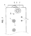
- FIG. 7 is a front view showing a configuration of the driving unit
- FIG. 8 is a side view showing a configuration of a driving portion for driving an intermediate-transferring-body unit of the driving unit
- FIG. 9 is a perspective view for explaining a positioning and driving-connecting mechanism for the driving unit and the intermediate-transferring-body unit;
- FIG. 10 is a side view for explaining a driving-connecting mechanism for the driving unit and the intermediate-transferring-body unit;
- FIG. 11 is a perspective view for explaining the driving-connecting mechanism for the driving unit and the intermediate-transferring-body unit;
- FIG. 12 is an illustration showing another image forming apparatus to which the present invention can be applied.
- FIG. 13 is a perspective view for explaining a positioning and driving-connecting mechanism for a driving unit and an intermediate-transferring-body unit of a conventional image forming apparatus.
- FIG. 1 is an illustration showing a schematic configuration of a color laser printer that is an image forming apparatus of the embodiment of the present invention.
- reference numeral 2 denotes a color laser printer.
- the color laser printer 2 is provided with an image forming portion 2 A constituted by process cartridges 100 ( 100 Y, 100 M, 100 C, and 100 K) of colors of yellow (Y), magenta (M), cyan (C), and black (B) respectively having a photosensitive member drum 1 serving as an image bearing body rotating at a constant speed, a developing device 4 and charging means 3 , and an intermediate-transferring-body unit 9 A having an intermediate transferring body 9 serving as a toner-image conveying member for multiple-transferring toner images of various colors formed in the image forming portion 2 A, holding the multiple-transferred color images, and further transferring the multiple-transferred color images to a transferring material P which is a recording material fed from a feeding portion 2 B.
- a transferring material P which is a recording material fed from a feeding portion 2 B.
- the process cartridges 100 of various colors are detachably mounted to the body of a color laser printer body (hereafter referred to as printer body) 2 C so that a unit can be easily replaced in accordance with the service life of the photosensitive member drum 1 .
- the photosensitive member drum 1 is constituted by applying an organic-photoconductor layer to the outside of an aluminum cylinder and can rotate counterclockwise in accordance with the image forming operation by a drum motor set to a driving unit to be described later.
- the charging means 3 uniformly charges the surface of the photosensitive member drum 1 in accordance with an injection charging method.
- the developing device 4 changes an electrostatic latent image formed in accordance with exposure from scanner portions 6 ( 6 Y, 6 M, 6 C, and 6 K) to be described later to the photosensitive member drum 1 to a visible image so as to form a visible image of toners of various colors by sleeves 5 arranged on the photosensitive member drum 1 at very small intervals.
- each of developing devices 4 of various colors feeds the toner in a vessel by a feed mechanism, applies the powder obtained by mixing toner (nonmagnetic) and developer (magnetic) to the periphery of the sleeves 5 and then performs toner development by relating the toner in the powder to an electrostatic latent image of the photosensitive member drum 1 .
- reference numeral 6 ( 6 Y, 6 M, 6 C, and 6 K) denotes a scanner unit serving as a scanner portion provided with a not-illustrated laser diode and a polygon mirror 6 a .
- the scanner portion 6 emits image light corresponding to the image signal to the polygon mirror 6 a by the laser diode.
- the polygon mirror 6 a is rotated at a high speed by a scanner motor.
- Reference numeral 115 denotes a support member for supporting the scanner units 6 Y, 6 M, 6 C, and 6 K.
- the intermediate-transferring-body unit 9 A is detachably mounted to the printer body 2 C. Moreover, the intermediate transferring body 9 provided for the intermediate-transferring-body unit 9 A rotates clockwise synchronously with the peripheral speed of the photosensitive member drum 1 in order to multiple-transfer a toner image on the photosensitive member drum 1 visualized by each developing device 4 when forming a color image. Moreover, the intermediate transferring body 9 undergoing multiple transfer simultaneously multiple-transfers toner images of various colors on the intermediate transferring body to the transferring material P by conveying the transferring material P while holding the transferring material P together with a secondary transferring roller 10 to which a voltage is applied.
- the intermediate transferring body 9 is formed by a resin belt having a circumferential length of approx. 1,000 mm and suspended with a tension over such three axes as a driving roller 9 a , secondary-transfer opposite roller 9 b , and tension roller 9 c . Moreover, the intermediate transferring body 9 is supported by the printer body 2 C by using the driving roller 9 a as a fulcrum so as to rotate clockwise in accordance with the image forming operation because a driving force is transferred to the driving roller 9 a from the driving motor of the driving unit.
- the secondary transferring roller 10 constituting a secondary transferring portion for simultaneously multiple-transferring toner images of various colors on the intermediate transferring body to the transferring material P is detachably mounted to the intermediate transferring body 9 , which is constituted by winding a middle-resistance foamed elastic body on a metallic shaft, is vertically movable, and has a driving force.
- the secondary transferring roller 10 is separated from the intermediate transferring body 9 as shown by a broken line so as not to disorder toner images on the intermediate transferring body 9 while toner images of four colors are formed on the intermediate transferring body 9 , before the toner images on the intermediate transferring body 9 reach the secondary transferring portion. Then, secondary transferring roller 10 is moved to an upper position shown by a continuous line where the intermediate transferring body 9 is pressed at a predetermined pressure through the transferring material P by a not-illustrated cam member.
- the fixing portion 17 is constituted by a fixing roller 18 for adding heat to the transferring material P and a pressure roller 9 for pressure-welding the transferring material P to the fixing roller 18 so as to convey the transferring material P while heating and pressurizing the transferring material P by rotating rollers 18 and 19 which are hollow rollers and which respectively have a not-illustrated built-in heater.
- the fixing device 17 the transferring material P holding toner images is conveyed by the fixing roller 18 and pressure roller 19 and heated and pressurized and resultantly, toner images are fixed to the transferring material P.
- the sheet feeding portion 2 B for feeding the transferring material P to the image forming portion 2 A is provided with a cassette 7 storing a plurality of transferring material sheets P, a pickup roller 8 a , a feeding roller 8 b , a retard roller 8 c for preventing duplicate feed, a sheet-feeding guide plate 8 d , and a registration roller 8 e.
- the pickup roller 8 a rotates in accordance with the image forming operation when an image is formed to separate and feed the transferring material sheets P in the cassette 7 one by one and the transferring material sheets P reach the registration roller 8 e via the guide plate 8 d by the feeding roller 8 b .
- the registration roller 8 e performs the non-rotational operation for making the transferring material P stop and wait under the image forming operation and the rotational operation for conveying the transferring material P toward the intermediate transferring body 9 in accordance with a predetermined sequence and aligns a toner image with the transferring material P in a transferring step which is the next step.
- reference numeral 14 denotes an intermediate-transferring-body cleaning unit.
- the intermediate-transferring-body cleaning unit 14 is constituted by a cleaning blade 12 a , a pressure spring 12 b for pressing the cleaning blade 12 a against the intermediate transferring body 9 , a fur brush 13 , and a cleaner vessel 14 a for holding the blade 12 a , spring 12 b , and brush 13 .
- the pickup roller 8 a rotates and one of the transferring material sheets P in the cassette 7 is separated and the separated transferring material sheet 7 is conveyed to the registration roller 8 e .
- the photosensitive member drum 1 and the intermediate transferring body 9 respectively rotate at a predetermined peripheral speed V in the direction of an arrow.
- the point E that is a start point for writing an image coincides with the point S on the intermediate transferring body 9 at the position of the point T. That is, the image is formed clockwise by using the intermediate transferring body 9 corresponding to the point S as a front end.
- a yellow image is primary-transferred to the periphery of the intermediate transferring body 9 as described below. That is, the yellow image is irradiated with a laser beam by the scanner portion 6 Y to form a yellow latent image on the photosensitive member drum 1 .
- the developing device 4 is driven simultaneously with formation of the latent image to develop yellow by applying a voltage having the same polarity and an approximately equal potential as those of the photosensitive member drum 1 to the sleeve 5 so that yellow toner attaches to the latent image on the photosensitive member drum 1 .
- the yellow toner image on the photosensitive member drum 1 is primary-transferred to the periphery of the intermediate transferring body 9 at the primary transferring position T 1 slightly downstream from the developing device 4 .
- a voltage having a polarity opposite to that of the yellow toner is applied to the intermediate transferring body 9 by transferring means 70 (refer to FIG. 4 ) and thereby, the yellow toner image is primary-transferred to the intermediate transferring body 9 .
- latent images are formed and developed in order of yellow, magenta, cyan, and black and then, toner-transferred to the intermediate transferring body 9 at primary positions T 1 , T 2 , T 3 , and T 4 , and a full-color image formed by four types of toners such as yellow, magenta, cyan, and black on the surface of the intermediate transferring body 9 .
- the full-color image on the intermediate transferring body 9 is transferred to the transferring material P by simultaneously moving the secondary transferring roller 10 waiting below the full-color image of four colors when the image is formed and not contacting with the intermediate transferring body 9 upward by a not-illustrated cam, holding the transferring material P by the secondary transferring portion T 5 together with the intermediate transferring body 9 , and simultaneously applying a bias having a characteristic opposite to that of toner to the secondary transferring roller 10 .
- the transferring material P to which the image is transferred at the secondary transferring portion T 2 is separated from the intermediate transferring body 9 and conveyed to the fixing portion 17 .
- the transferring material P is toner-fixed at the fixing portion 17 and ejected onto an ejecting tray 37 at the upper portion of the printer body through ejecting rollers 20 , 21 , and 22 by turning the image surface downward. Thereby, the image forming operation is completed.
- FIG. 2 is an illustration showing a state of setting the process cartridge 100 to the printer body 2 C.
- a not-illustrated guide rail portion for moving the process cartridge 100 along the removing direction shown by an arrow is formed in the printer body and a user inserts the process cartridge 100 along the guide rail portion.
- a not-illustrated guide rail portion, formed for removing and changing the intermediate-transferring-body unit 9 A along the direction orthogonal to the removing direction of the process cartridge 100 is formed at the inside of the front and rear plates of the printer body and a user sets the intermediate transferring unit 9 A in the printer body along the guide rail portion.
- photosensitive member drums 1 and a driving unit 103 for driving the intermediate transferring body 9 A are positioned and fixed at the back of a rear plate 101 serving as the frame of the printer body 2 C located at the inner part in the inserting direction of the process cartridge 100 of the printer body 2 C.
- the driving unit has means for driving the process cartridge and holds and positions the process cartridge.
- FIG. 3 is an illustration showing an elevating mechanism of the intermediate-transferring-body unit 9 A.
- an object shown by a continuous line shows a state in which the intermediate transferring body 9 of the intermediate-transferring-body unit 9 A is separated from the photosensitive member drum 1 .
- this elevating mechanism is provided with eccentric cams 210 and 216 fixed to an eccentric cam shaft 209 and the eccentric cams 210 and 216 are respectively constituted so as to perform the same rotating operation by a not-illustrated link mechanism. Moreover, the eccentric cams 210 and 216 rotate by 180° when a user sets the process cartridge 100 and intermediate-transferring-body unit 9 A to the printer body 2 C and then rotate a not-illustrated contacting-separating lever to raise an eccentric-cam receiving portion 205 a formed on a frame 129 of the intermediate-transferring-body unit 9 A.
- the intermediate-transferring-body unit 9 A rises almost in parallel and as a result, the intermediate transferring body 9 contacts with the photosensitive member drum 1 .
- the intermediate-transferring-body unit 9 A rises as described above, the intermediate-transferring-body unit 9 A is driving-connected with the driving unit 103 .
- the driving unit 103 will be described below which drives the photosensitive member drum 1 and intermediate transferring body 9 .
- the driving unit 103 is provided with driving portions 103 Y, 103 M, 103 C, and 103 B for driving photosensitive member drums 1 of colors Y, M, C, and B and a driving portion 103 ITB for driving the intermediate transferring body 9 and these driving portions 103 Y, 103 M, 103 C, 103 B, and 103 ITB are respectively accurately positioned and fixed on a frame of the driving unit 103 (hereafter referred to as driving frame) 104 .
- the driving frame 104 is formed by a sheet metal thicker than the body rear plate 101 and has a shape whose stiffness is larger (stronger) than that of the body rear plate 101 by forming a bent portion 104 a on the frame 104 .
- the driving portions 103 Y, 103 M, 103 C, and 103 B for various colors are respectively provided with a fixed motor 45 , a pinion 46 fixed to a motor shaft 45 a of the motor 45 , a large gear 48 fixed to a drum driving shaft 49 , an intermediate gear 47 engaged with the pinion 46 and large gear 48 , an almost-spherical positioning portion 57 formed at the front end of the drum driving shaft 49 , a bearing 51 for supporting the drum driving shaft 49 so as not to move in the shaft direction, and a triangular coupling 52 shown in FIG. 7 .
- a rotary encoder 53 is set to the opposite end of the drum driving shaft 49 and moreover, two rotation detecting means 54 for detecting the rotational fluctuation of the drum driving shaft 49 by the rotary encoder 53 are accurately set to positions opposite to each other by 180° about the drum driving shaft 49 . Furthermore, it is possible to minimize the rotational fluctuation of the drum driving shaft 49 for each color by detecting the rotational fluctuation of one turn of the photosensitive member drum 1 by these rotation detecting means 54 and controlling the next rotation of the drum motor 45 in accordance with a driving signal for canceling the rotational fluctuation of one turn of the photosensitive member drum 1 .
- the intermediate-transferring-body-unit driving portion 103 ITB is provided with a fixed motor 45 serving as driving means for driving an intermediate transferring body 9 , a pinion 120 fixed to a motor shaft 45 a , a large gear 122 fixed to a driving shaft 125 , an intermediate gear 121 engaged with the pinion 120 and a large gear 122 , a bearing 51 for supporting the driving shaft 125 so as not to move in the shaft direction, and a driving coupling 124 serving as a second driving transmitting portion for transmitting the driving of the motor 45 to the intermediate-transferring-body unit 9 A (intermediate transferring body 9 ).
- the driving coupling 124 is supported so as to be movable in the thrust direction along the driving shaft 125 in a coupling holder 123 and urged in the intermediate-transferring-body direction by a return spring 126 .
- reference numeral 130 denotes a rotatable connection cancel lever for canceling the connection between the driving coupling 124 and a coupling 127 of the intermediate-transferring-body unit 9 A serving as a first driving transmitting portion and 133 denotes a cancel spring having an urging force larger than that of the return spring 126 .
- the connection cancel lever 130 is rotated clockwise by the cancel spring 133 as shown in FIG. 8 to hold the driving coupling 124 at a withdrawal position for canceling the driving connection with the coupling 127 of the intermediate-transferring-body unit 9 A.
- a convex shape 210 a is formed on the side face of the eccentric cam 210 and in the separate state of the intermediate-transferring-body unit 9 A shown in FIG. 8 , the convex shape 210 a separates from the connection cancel lever 130 . Therefore, the connection cancel lever 130 moves to the withdrawal position.
- the connection cancel lever 130 rotates counterclockwise by overwhelming the urging force of the cancel spring 123 .
- the driving coupling 124 is released from the inhibiting force of the connection cancel lever 130 , slides in the direction of the intermediate-transferring-body unit by the urging force of the return spring 126 along the driving shaft 125 , and connects with the coupling 127 of the intermediate-transferring-body unit 9 A.
- reference numeral 105 a denotes a first positioning pin and 105 b denotes a second positioning pin which serve as a first positioning portion and a second positioning portion respectively at the time of setting the driving unit 103 to the body rear plate 101 .
- reference numeral 131 denotes a positioning member serving as a positioning portion for positioning the intermediate-transferring-body unit 9 A when the intermediate-transferring-body unit 9 A is set to the printer body 2 C and the positioning member 131 is accurately set on the driving frame 104 in x- and y-directions on the basis of the first positioning pin 105 a together with the drum driving shaft 49 for driving the photosensitive member drums 1 of various colors.
- two positioning members 131 are horizontally set to the driving frame 104 while keeping an interval capable of fitting with a positioning-fitting member 132 set on the intermediate transferring frame 129 .
- the positioning member 131 protrudes toward the intermediate-transferring-body unit from an opening 110 a formed on the body rear plate 101 .
- the coupling 52 serving as a part of the driving unit 103 protrudes into the apparatus from the driving unit 103 by passing through an opening 72 of an apparatus body frame 101 .
- the positioning member 131 protrudes toward the intermediate-transferring-body unit, when a user raises the intermediate-transferring-body unit 9 A described above, the positioning-fitting member 132 set onto the intermediate transferring frame 129 shown in FIG. 9 accurately fits between two positioning members 131 on the driving frame 104 . Thereby, the intermediate-transferring-body unit 9 A is accurately positioned to the printer body 2 C on the basis of the first positioning pin (first reference axis) 105 a.
- a positional error of the driving connecting portion produced in the driving unit 103 is only a dimensional error D 1 of the dimension L 1 between the driving shaft 125 and the positioning member 131 .
- the dimensional error D 1 can be controlled to approx. 30 ⁇ m when working a sheet metal.
- the setting/removing operability of the intermediate-transferring-body unit 9 A to or from the printer body 2 C is improved, a user can easily perform maintenance, and it is possible to improve the positional accuracy of the intermediate-transferring-body unit 9 A.
- the intermediate-transferring-body unit 9 A driving-connects with the driving unit 103 connection is not disabled or irregular rotation of the driving roller 9 a does not occur and thus, it is possible to provide a high-accuracy and high-quality full-color image.
- reference holes 106 and 106 b accurately fitting with the first positioning pin 105 a and the second positioning pin 105 b of the driving unit 103 are formed on the body rear plate 101 .
- the reference hole 106 a fits with the first positioning pin 105 a in both x and y directions to position the driving unit 103 .
- the second reference hole 106 b into which the second positioning pint 105 b is inserted has a racetrack shape hole extending in the x direction and fitted with the second positioning pin 105 b and positioned only in the y direction.
- the driving frame 104 by constituting the driving frame 104 by a sheet metal thicker than the body rear plate 101 and forming a bent portion on the driving frame 104 to form a shape having a large stiffness, it is possible to improve the deterioration of the positional accuracy of the intermediate-transferring-body unit 9 A due to a body deformation caused by an insufficient stiffness due to deterioration of the flatness of the body rear plate 101 .
- connection cancel lever 130 thus rotates, the driving coupling 124 is released from the inhibiting force of the connection cancel lever 130 , slides in the intermediate-transferring-body unit along the driving shaft 125 in accordance with the urging force of the return spring 126 , and connects with the coupling 127 of the intermediate-transferring-body unit 9 A.
- the positioning-fitting member 132 of the intermediate-transferring-body unit 9 A accurately fits between the positioning members 131 and the intermediate transferring body 9 is positioned to the printer body 2 C.
- An image forming apparatus which forms a color image on a transferring material by successively transferring toner images of a plurality of colors formed on a plurality of image bearing bodies arranged in parallel to an intermediate transferring body and then simultaneously transferring the toner images of a plurality of colors to a transferring material.
- FIG. 1 it is needless to say, as shown in FIG.
- the present invention can be applied not only to the above image forming apparatus, but also to an image forming apparatus for successively transferring toner images of a plurality of colors formed on a plurality of image bearing bodies arranged in parallel to a transferring material conveyed by a transferring-material conveying member, in which a unit 80 A provided with a conveying member 80 for conveying toner images through the transferring material is detachably mounted to the apparatus body.
Applications Claiming Priority (2)
| Application Number | Priority Date | Filing Date | Title |
|---|---|---|---|
| JP2001369244A JP2003167411A (ja) | 2001-12-03 | 2001-12-03 | 画像形成装置 |
| JP369244/2001 | 2001-12-03 |
Publications (2)
| Publication Number | Publication Date |
|---|---|
| US20030103780A1 US20030103780A1 (en) | 2003-06-05 |
| US6839532B2 true US6839532B2 (en) | 2005-01-04 |
Family
ID=19178671
Family Applications (1)
| Application Number | Title | Priority Date | Filing Date |
|---|---|---|---|
| US10/305,942 Expired - Fee Related US6839532B2 (en) | 2001-12-03 | 2002-11-29 | Image forming apparatus with improved conveying unit positioning |
Country Status (2)
| Country | Link |
|---|---|
| US (1) | US6839532B2 (ja) |
| JP (1) | JP2003167411A (ja) |
Cited By (6)
| Publication number | Priority date | Publication date | Assignee | Title |
|---|---|---|---|---|
| US20040202496A1 (en) * | 2003-04-14 | 2004-10-14 | Konica Minolta Business Technologies, Inc. | Color image forming apparatus and its control method |
| US20050214034A1 (en) * | 2004-03-26 | 2005-09-29 | Sharma Pramod K | Shared high voltage power supply for image transfer in an image forming device |
| US20070019990A1 (en) * | 2005-07-20 | 2007-01-25 | Kabushiki Kaisha Toshiba | Image forming apparatus and process unit |
| US9052674B2 (en) | 2012-09-21 | 2015-06-09 | Brother Kogyo Kabushiki Kaisha | Image forming apparatus with metal and resin frame components |
| US9131113B2 (en) | 2010-11-01 | 2015-09-08 | Nagravision S.A. | Method for creating an enhanded data stream |
| US9436129B2 (en) * | 2014-07-17 | 2016-09-06 | Kyocera Document Solutions Inc. | Drive transmission mechanism and image forming apparatus with the same |
Families Citing this family (10)
| Publication number | Priority date | Publication date | Assignee | Title |
|---|---|---|---|---|
| US7555238B2 (en) * | 2004-09-29 | 2009-06-30 | Brother Kogyo Kabushiki Kaisha | Image-forming device and angularly shifted belt unit |
| JP4719043B2 (ja) * | 2006-03-17 | 2011-07-06 | 株式会社リコー | 駆動制御装置および画像形成装置 |
| JP2008225205A (ja) * | 2007-03-14 | 2008-09-25 | Ricoh Co Ltd | 画像形成装置 |
| JP5158508B2 (ja) * | 2008-09-30 | 2013-03-06 | 株式会社リコー | 画像形成装置 |
| JP2011102858A (ja) * | 2009-11-10 | 2011-05-26 | Fuji Xerox Co Ltd | 画像形成装置 |
| JP2011209567A (ja) * | 2010-03-30 | 2011-10-20 | Kyocera Mita Corp | 回転センサの取付構造及びこれを備えた画像形成装置 |
| JP5862130B2 (ja) * | 2011-09-08 | 2016-02-16 | 富士ゼロックス株式会社 | 画像形成装置 |
| JP6098554B2 (ja) | 2014-03-11 | 2017-03-22 | ブラザー工業株式会社 | 画像形成装置 |
| JP6390316B2 (ja) * | 2014-09-30 | 2018-09-19 | ブラザー工業株式会社 | 画像形成装置 |
| JP6659083B2 (ja) | 2014-12-12 | 2020-03-04 | キヤノン株式会社 | 駆動力伝達装置 |
Citations (4)
| Publication number | Priority date | Publication date | Assignee | Title |
|---|---|---|---|---|
| JPH08314290A (ja) * | 1995-05-20 | 1996-11-29 | Ricoh Co Ltd | 画像形成装置 |
| JP2000187399A (ja) * | 1998-12-21 | 2000-07-04 | Seiko Epson Corp | 画像形成装置 |
| JP2002287455A (ja) * | 2001-03-28 | 2002-10-03 | Ricoh Co Ltd | 画像形成装置 |
| US6473580B1 (en) * | 1997-03-28 | 2002-10-29 | Canon Kabushiki Kaisha | Driving force receiving member, shaft coupling, toner image bearing member, process cartridge and electrophotographic image forming apparatus |
Family Cites Families (1)
| Publication number | Priority date | Publication date | Assignee | Title |
|---|---|---|---|---|
| JP3658262B2 (ja) * | 1999-02-23 | 2005-06-08 | キヤノン株式会社 | 画像形成装置 |
-
2001
- 2001-12-03 JP JP2001369244A patent/JP2003167411A/ja active Pending
-
2002
- 2002-11-29 US US10/305,942 patent/US6839532B2/en not_active Expired - Fee Related
Patent Citations (4)
| Publication number | Priority date | Publication date | Assignee | Title |
|---|---|---|---|---|
| JPH08314290A (ja) * | 1995-05-20 | 1996-11-29 | Ricoh Co Ltd | 画像形成装置 |
| US6473580B1 (en) * | 1997-03-28 | 2002-10-29 | Canon Kabushiki Kaisha | Driving force receiving member, shaft coupling, toner image bearing member, process cartridge and electrophotographic image forming apparatus |
| JP2000187399A (ja) * | 1998-12-21 | 2000-07-04 | Seiko Epson Corp | 画像形成装置 |
| JP2002287455A (ja) * | 2001-03-28 | 2002-10-03 | Ricoh Co Ltd | 画像形成装置 |
Cited By (9)
| Publication number | Priority date | Publication date | Assignee | Title |
|---|---|---|---|---|
| US20040202496A1 (en) * | 2003-04-14 | 2004-10-14 | Konica Minolta Business Technologies, Inc. | Color image forming apparatus and its control method |
| US7248820B2 (en) * | 2003-04-14 | 2007-07-24 | Konica Minolta Business Technologies, Inc. | Color image forming apparatus and a method for operating |
| US20050214034A1 (en) * | 2004-03-26 | 2005-09-29 | Sharma Pramod K | Shared high voltage power supply for image transfer in an image forming device |
| US7289757B2 (en) * | 2004-03-26 | 2007-10-30 | Lexmark International, Inc. | Shared high voltage power supply for image transfer in an image forming device |
| US20070019990A1 (en) * | 2005-07-20 | 2007-01-25 | Kabushiki Kaisha Toshiba | Image forming apparatus and process unit |
| US7292808B2 (en) * | 2005-07-20 | 2007-11-06 | Kabushiki Kaisha Toshiba | Image forming apparatus and process unit |
| US9131113B2 (en) | 2010-11-01 | 2015-09-08 | Nagravision S.A. | Method for creating an enhanded data stream |
| US9052674B2 (en) | 2012-09-21 | 2015-06-09 | Brother Kogyo Kabushiki Kaisha | Image forming apparatus with metal and resin frame components |
| US9436129B2 (en) * | 2014-07-17 | 2016-09-06 | Kyocera Document Solutions Inc. | Drive transmission mechanism and image forming apparatus with the same |
Also Published As
| Publication number | Publication date |
|---|---|
| US20030103780A1 (en) | 2003-06-05 |
| JP2003167411A (ja) | 2003-06-13 |
Similar Documents
| Publication | Publication Date | Title |
|---|---|---|
| US6839532B2 (en) | Image forming apparatus with improved conveying unit positioning | |
| US8165493B2 (en) | Process cartridge and electrophotographic image forming apparatus | |
| JP3566697B2 (ja) | プロセスカートリッジ、電子写真画像形成装置、及び、離隔機構 | |
| US7349649B2 (en) | Process cartridge, positioning mechanism therefor and electrophotographic image forming apparatus | |
| US7184686B2 (en) | Process cartridge having developing roller and photosensitive drum that can contact and become spaced apart from each other and electrophotographic image forming apparatus mounting such cartridge | |
| US8160478B2 (en) | Process cartridge and image forming apparatus | |
| US6795671B2 (en) | Image forming apparatus featuring switchable, contact and spaced, clutch-operated developing units | |
| US6704528B1 (en) | Image forming apparatus having detachable cleaning unit | |
| US20090123201A1 (en) | Image forming apparatus | |
| US20050117934A1 (en) | Process cartridge, mounting method of electrophotographic photosensitive drum and replacing method of the photosensitive drum | |
| US6438341B1 (en) | Drive transmission for photosensitive drum with first and second engaging members, and urging means for engaging the first and second engaging members | |
| JPH10301464A (ja) | 画像形成装置 | |
| US8798499B2 (en) | Image forming apparatus having image bearing member guide portions | |
| US5585892A (en) | Image forming apparatus with positioning member of frame engaging shaft of roller of photosensitive belt | |
| JP2000227736A (ja) | 画像形成装置 | |
| JP4181769B2 (ja) | 画像形成装置 | |
| US20170289385A1 (en) | Exposure device, led head, image forming apparatus and image reading apparatus | |
| JP2009139518A (ja) | 画像形成装置 | |
| US6379482B1 (en) | Manufacturing device and method of the exposure device | |
| JP3805059B2 (ja) | 画像形成装置 | |
| US6389252B2 (en) | Method and apparatus for moving a drum into a nip | |
| JP2004144918A (ja) | 画像形成装置 | |
| US7177574B2 (en) | Image forming apparatus and developing gap adjusting method in image forming apparatus | |
| JP5081547B2 (ja) | 画像形成装置およびプロセスカートリッジ | |
| US6823165B1 (en) | Method and apparatus for applying a constant load to a roller |
Legal Events
| Date | Code | Title | Description |
|---|---|---|---|
| AS | Assignment |
Owner name: CANON KABUSHIKI KAISHA, JAPAN Free format text: ASSIGNMENT OF ASSIGNORS INTEREST;ASSIGNOR:HOASHI, SHIGERU;REEL/FRAME:013537/0528 Effective date: 20021122 |
|
| CC | Certificate of correction | ||
| FPAY | Fee payment |
Year of fee payment: 4 |
|
| FPAY | Fee payment |
Year of fee payment: 8 |
|
| REMI | Maintenance fee reminder mailed | ||
| LAPS | Lapse for failure to pay maintenance fees | ||
| STCH | Information on status: patent discontinuation |
Free format text: PATENT EXPIRED DUE TO NONPAYMENT OF MAINTENANCE FEES UNDER 37 CFR 1.362 |
|
| FP | Lapsed due to failure to pay maintenance fee |
Effective date: 20170104 |