US6776946B2 - Method and apparatus for rubber extruding - Google Patents
Method and apparatus for rubber extruding Download PDFInfo
- Publication number
- US6776946B2 US6776946B2 US09/989,390 US98939001A US6776946B2 US 6776946 B2 US6776946 B2 US 6776946B2 US 98939001 A US98939001 A US 98939001A US 6776946 B2 US6776946 B2 US 6776946B2
- Authority
- US
- United States
- Prior art keywords
- rubber
- port
- die plate
- extruding
- discharge port
- Prior art date
- Legal status (The legal status is an assumption and is not a legal conclusion. Google has not performed a legal analysis and makes no representation as to the accuracy of the status listed.)
- Expired - Lifetime
Links
Images


Classifications
-
- B—PERFORMING OPERATIONS; TRANSPORTING
- B29—WORKING OF PLASTICS; WORKING OF SUBSTANCES IN A PLASTIC STATE IN GENERAL
- B29C—SHAPING OR JOINING OF PLASTICS; SHAPING OF MATERIAL IN A PLASTIC STATE, NOT OTHERWISE PROVIDED FOR; AFTER-TREATMENT OF THE SHAPED PRODUCTS, e.g. REPAIRING
- B29C48/00—Extrusion moulding, i.e. expressing the moulding material through a die or nozzle which imparts the desired form; Apparatus therefor
- B29C48/25—Component parts, details or accessories; Auxiliary operations
- B29C48/30—Extrusion nozzles or dies
- B29C48/305—Extrusion nozzles or dies having a wide opening, e.g. for forming sheets
-
- B—PERFORMING OPERATIONS; TRANSPORTING
- B29—WORKING OF PLASTICS; WORKING OF SUBSTANCES IN A PLASTIC STATE IN GENERAL
- B29C—SHAPING OR JOINING OF PLASTICS; SHAPING OF MATERIAL IN A PLASTIC STATE, NOT OTHERWISE PROVIDED FOR; AFTER-TREATMENT OF THE SHAPED PRODUCTS, e.g. REPAIRING
- B29C48/00—Extrusion moulding, i.e. expressing the moulding material through a die or nozzle which imparts the desired form; Apparatus therefor
- B29C48/022—Extrusion moulding, i.e. expressing the moulding material through a die or nozzle which imparts the desired form; Apparatus therefor characterised by the choice of material
-
- B—PERFORMING OPERATIONS; TRANSPORTING
- B29—WORKING OF PLASTICS; WORKING OF SUBSTANCES IN A PLASTIC STATE IN GENERAL
- B29C—SHAPING OR JOINING OF PLASTICS; SHAPING OF MATERIAL IN A PLASTIC STATE, NOT OTHERWISE PROVIDED FOR; AFTER-TREATMENT OF THE SHAPED PRODUCTS, e.g. REPAIRING
- B29C48/00—Extrusion moulding, i.e. expressing the moulding material through a die or nozzle which imparts the desired form; Apparatus therefor
- B29C48/03—Extrusion moulding, i.e. expressing the moulding material through a die or nozzle which imparts the desired form; Apparatus therefor characterised by the shape of the extruded material at extrusion
- B29C48/07—Flat, e.g. panels
-
- B—PERFORMING OPERATIONS; TRANSPORTING
- B29—WORKING OF PLASTICS; WORKING OF SUBSTANCES IN A PLASTIC STATE IN GENERAL
- B29C—SHAPING OR JOINING OF PLASTICS; SHAPING OF MATERIAL IN A PLASTIC STATE, NOT OTHERWISE PROVIDED FOR; AFTER-TREATMENT OF THE SHAPED PRODUCTS, e.g. REPAIRING
- B29C48/00—Extrusion moulding, i.e. expressing the moulding material through a die or nozzle which imparts the desired form; Apparatus therefor
- B29C48/03—Extrusion moulding, i.e. expressing the moulding material through a die or nozzle which imparts the desired form; Apparatus therefor characterised by the shape of the extruded material at extrusion
- B29C48/12—Articles with an irregular circumference when viewed in cross-section, e.g. window profiles
-
- B—PERFORMING OPERATIONS; TRANSPORTING
- B29—WORKING OF PLASTICS; WORKING OF SUBSTANCES IN A PLASTIC STATE IN GENERAL
- B29K—INDEXING SCHEME ASSOCIATED WITH SUBCLASSES B29B, B29C OR B29D, RELATING TO MOULDING MATERIALS OR TO MATERIALS FOR MOULDS, REINFORCEMENTS, FILLERS OR PREFORMED PARTS, e.g. INSERTS
- B29K2019/00—Use of rubber not provided for in a single one of main groups B29K2007/00 - B29K2011/00, as moulding material
Definitions
- the present invention relates to a rubber extruding method and a rubber extruding apparatus, capable of performing extruding of a rubber extruded intermediate having a thickness varying in the width direction with good precision.
- rubber extruded intermediates such as a sidewall rubber, a clinch rubber, a tread rubber and others are employed.
- Such rubber extruded intermediates are extruded from a rubber extruder having a die plate.
- a tread rubber “a” is illustrated as such a rubber extruded intermediate.
- these rubber extruded intermediates “a” are each extruded as an article having a thickness varying in a width direction.
- a distribution vp of an extruding speed v is profiled with a value different according to a portion like a sectional shape of the rubber extruded intermediate. That is, the extruding speed v is non-uniform in the width direction. Furthermore, if an extruding rate of an extruder varies, the extruding speed distribution vp loses more of balance thereof, easily accelerating non-uniformity in extruding speed to an greater extent. In such a case, there arises a problem that passage resistance of rubber passing through the die plate largely varies at positions along the width direction, thereby causing a sectional shape of a rubber extruded intermediate not to be constant.
- the present invention has been contrived in light of the problems as described above and it is an object of the present invention to provide a rubber extruding method and a rubber extruding apparatus, working to maintain a sectional shape of a rubber extruded intermediate to be constant even in a case where an extruding rate of an extruder or the like varied.
- the first present invention is a rubber extruding method extruding a rubber extruded intermediate by discharging rubber from a discharge port of a die plate mounted to an outlet of an extruder, wherein
- said die plate has an inflow port through which rubber flows in from the extruder side
- said discharge port is of a flat shape with a lower section having a smaller height and a higher section having a larger height and with a height varying along a width direction to thereby extrude said rubber extruded intermediate with a thickness varying along a width direction, and
- each extruding speed of said rubber extruded intermediate is made uniform at positions along a width direction thereof.
- the second present invention is a rubber extruding apparatus extruding a rubber extruded intermediate by discharging rubber from a discharge port of a die plate mounted to an outlet of an extruder, wherein
- said die plate has an inflow port through which rubber flows in from the extruder side
- said discharge port is of a flat shape with a lower section having a smaller height and a higher section having a larger height and with a height varying along a width direction to thereby extrude said rubber extruded intermediate with a thickness varying along a width direction, and
- said die plate satisfies the following relation:
- Sso is an area per unit width in said lower section
- Ssi is an area at said inflow port through which rubber flowing through said area Sso per unit width in said lower section passes
- Sho is an area per unit width in said higher section
- Shi is an area at said inflow port through which rubber flowing through said area Sho per unit width in said higher section passes.
- FIG. 1 is a perspective view showing one example of a rubber extruding apparatus relating to the present invention
- FIGS. 2A to 2 E are diagrams showing accumulation states in an accumulator
- FIG. 3 is a sectional view describing a flow path in an extrusion head
- FIG. 4 is an exploded, perspective view showing a rubber flow path, divided into two parts, one on the other, in a die plate;
- FIG. 5 is an exploded, perspective view showing an intermediate flow path, divided into two parts, one on the other, in a preformer;
- FIG. 6 is a diagram showing a discharge port and inflow port of the die plate together as viewed from the front side;
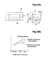
- FIGS. 7A and 7B are a descriptive diagram of a die plate for use in a test and a graph showing test results, respectively;
- FIG. 8 is diagrams showing variations in shape of inlets and outlets of respective various flow paths in the order in which rubber flows through the inlets and outlets;
- FIG. 9 is a diagram showing illustrating the other of the geometrical relationship between a receiving port of the preformer and a discharge port of the die plate.
- FIG. 10A is a diagram showing an extruding speed distribution in a prior art practice and FIG. 10B is a diagram showing an extruding speed distribution in the present invention.
- FIG. 1 a case is shown in which a rubber extruding apparatus 1 used in a rubber extruding method of the present invention is applied in a tread ring production line.
- this tread ring production line after a tread rubber is extruded as a rubber extruded intermediate G, the intermediate G is further forming into a tire preform such as a tread ring by directly fixing the intermediate G onto a forming drum.
- the rubber extruding apparatus 1 comprises an extruder 2 and a feed means 4 .
- the feed means 4 feeds the rubber extruded intermediate G continuously extruded from the extruder 2 to a folding drum 3 to form an annular tread ring.
- the feed means 4 is constituted of, for example, an accumulator 5 , a fixing conveyor 6 and a cutting device 7 .
- the folding drum 3 can reciprocate in the axial direction thereof in this example and shows a so-called belt drum capable of fixing parts such as a belt and a band at another position.
- the accumulator 5 has an accumulation part 9 drooping the rubber extruded intermediate G extruded from the extruder 2 in a “U” shape for temporary accumulation.
- the extruder 2 is controlled on its screw rotation according to an accumulation amount in the accumulation part 9 .
- FIGS. 2A to 2 (E) variations in accumulation amount are shown.
- the fixing conveyor 6 is constituted of a first conveyor portion 6 A receiving the rubber extruded intermediate G from the accumulator 5 for transportation, and a second conveyor portion 6 B provided to the first conveyor 6 A for free transit by way of the cutting device 7 and transporting cut intermediates G 1 to the folding drum 3 for fixing.
- the cutting device 7 has a cutting blade (not shown) such as an ultrasonic cutter, for example, and cuts the rubber extruded intermediate G transported by the first conveyor portion 6 A into pieces with prescribed lengths (for example, a length required for fully winding each piece around the folding drum 3 ).
- a cutting blade such as an ultrasonic cutter, for example, and cuts the rubber extruded intermediate G transported by the first conveyor portion 6 A into pieces with prescribed lengths (for example, a length required for fully winding each piece around the folding drum 3 ).
- the first conveyor portion 6 A can measure its transport distances and is controlled by a control means intermittently feeding the rubber extruded intermediate G by the prescribed length thereof at each time. Accordingly, the cut intermediates G 1 each with the prescribed length are transported onto the second conveyor portion 6 B.
- the second conveyor portion 6 B includes a conveyor body 12 supported in the upstream side thereof by a frame 11 freely rotatably about a pivotal point J.
- the conveyor body 12 is constituted of, for example, a belt conveyor and the top end of a rod of a cylinder 15 mounted on a side of the frame 11 is coupled with it. Therefore, by an extending or shrinking action of the rod, the conveyor body 12 swings about the pivotal point J upward or downward. With this swing action used, the conveyor body 12 can move between a lower position Q 1 at which the distal end thereof is close to the forming drum 3 to fix the cut intermediate G 1 and an upper position Q 2 at which the distal end thereof is apart from the folding drum 3 for waiting.
- the feed means 4 includes sensors 13 U and 13 L detecting the upper limit value and lower limit value of the accumulation amount in the accumulator 5 , and a control means 14 controlling a rotation speed of a drive motor M (that is a rotation speed of a screw) of the extruder 2 based on a detection signal of the sensor 13 U or 13 L.
- a control means 14 controlling a rotation speed of a drive motor M (that is a rotation speed of a screw) of the extruder 2 based on a detection signal of the sensor 13 U or 13 L.
- the extruder 2 can desirably perform extruding, maintaining a sectional shape of the rubber extruded intermediate G to be constant even if an extruding rate is varied by the rotation control. Therefore, in this embodiment, by giving a function for adjusting an extruding speed to the die plate 20 , the extruding speed V, as shown in FIG. 10B, are made uniform at positions along the width direction of the rubber extruded intermediate G.
- the action of the extruding speed V to uniformity spreads a variation in a rubber extruding rate of the extruder, if any, uniformly across the entire intermediate in the width direction.
- a profile of the speed distribution VP does not lose a balance across a width.
- a sectional shape of the rubber extruded intermediate is kept constant.
- the extruder 2 as in FIG. 1, comprises an extrusion head 22 and a main body 23 feeding rubber into the extrusion head 22 . Furthermore, the die plate 20 is mounted to the outlet of the extrusion head 22 .
- the main body 23 comprises a cylinder 25 disposed a screw 24 therein.
- the screw 24 can be rotation-driven by a drive motor M to extrude charged rubber from an extrusion outlet 25 A (shown in FIG. 3) at the fore end of the cylinder while kneading it.
- a drive motor M a motor capable of being controlled on a rotation speed thereof is preferably adopted.
- an inverter motor is used and a rotation speed thereof is freely adjusted by inverter control of the control means 14 .
- the die plate 20 is exchangeably mounted to the fore end of a head body 26 in the shape of a block fixed to the cylinder 25 .
- a preformer 27 preliminarily forming rubber is disposed adjacent to the die plate 20 on the upstream side thereof.
- the head body 26 has a guide flow path 29 guiding rubber from the cylinder 25 to the preformer 27 .
- the preformer 27 has a receiving port 31 i receiving rubber from the guide flow path 29 , a sending port 31 o feeding the rubber into the die plate 20 and an intermediate flow path 31 connecting the ports 31 i and 31 o therebetween.
- the die plate 20 has an inflow port 21 i through which the rubber from the intermediate flow path 31 flows in, a discharge port 21 o discharging the rubber, and a rubber flow path 21 connecting the ports 21 i and 21 o therebetween.
- the rubber flow path 21 and the intermediate flow path 31 are shown in respective exploded view, each divided into two parts, one on the other.
- the discharge port 21 o of the die plate 20 is formed in an opening shape adapted to a desired rubber extruded intermediate G, similar to a prior practice.
- the die plate 20 has a flat shape with a lower section 32 having a smaller height and higher sections 33 having a larger height.
- the die plate 20 has a height Ho varying along the width direction.
- Such a die plate 20 can be used in extruding the rubber extruded intermediate G, determined by the opening shape of the die plate 20 , and having a thickness varying along the width direction.
- the discharge port 21 o comprises, in this example, the center lower section 32 A of an constant height substantially located in the central portion, the higher sections 33 provided on both sides of the lower section 32 A and inclined sections 34 located between the lower section 32 A and the higher section 33 .
- the discharge port 21 o has an end lower section 32 B, at least one end E, in a triangular shape formed by gradually decreasing a height of the section toward the end E.
- the discharge port 21 o is not only flat at the bottom edge, but of a bilaterally symmetrical shape with the end lower sections 32 B formed at both ends thereof.
- the inflow port 21 i has a ratio (Ssi/Sso) of an area Sso per unit width in the lower section 32 at the discharge port 21 o and an area Ssi at the inflow port 21 i through which rubber flowing through the area Sso passes is larger than a ratio (Shi/Sho) of an area Sho per unit width in the higher section 33 at the discharge port 21 o and an area Shi at the inflow port 21 i through which rubber flowing through the area Sho passes. That is, the inflow port 21 i is formed such that the following relation is satisfied:
- value of the ratio (Ssi/Sso) is 1.0 or more. Note that as in this example, in a case where lower sections with a plurality of heights (for example, 2) 32 A and 32 B are present and if heights HsA and HsB satisfy in the following relation:
- the inflow port 21 i is formed such that area ratios of the sections 32 A and 32 B, (SsiA/SsoA) and (SsiB/SsoB) satisfy the following relation, which is the inversion, in inequality, of the above case:
- an area at the inflow port 21 i is designed relatively smaller in corresponding section to the higher section 33 with a large height Ho, through which rubber is easy to flow at the discharge port 21 o .
- an area at the inflow port 21 i is designed relative larger in a corresponding section of the lower section 32 through which rubber is hard to flow at the discharge port 21 o .
- the inventors of the present invention performed an extrusion test as shown in FIG. 7A in conditions that in the die plate 20 , a height Ho at the discharge port 21 o is constant, while a height Hi at the inflow port 21 i is varied and a pressure is constant.
- extruding speeds, volumes of extruded intermediates and thickness values of the extruded intermediates were compared. Results of the test are shown in FIG. 7 B.
- a ratio (Hi/Ho) of a height of the inflow port 21 i to that of the discharge port 21 o or an area ratio (Si/So) increases, an extruding speed, a volume of a extruded intermediate and a thickness of the extruded intermediate all increase individually.
- a degree of variation in extruding speed greatly varies, while degrees of variation in volume of the extruded intermediate and in thickness of the extruded intermediate are restricted to be small.
- the discharge port 21 o can be formed in conformity with a shape of a rubber extruded intermediate G, similar to a prior art practice.
- scooped parts 41 having a depth decreasing toward the end lower section 32 B from the inflow port 21 i are formed on the bottom surface of the rubber flow path 21 for the same purpose, thereby ensuring an area Ssi and realizing smoothness of a rubber flow.
- the intermediate flow path 31 of the preformer 27 exerts a function to realize a sufficient and smooth rubber flow into the protruding section 40 and the scooped section 41 .
- the intermediate flow path 31 is formed substantially larger in size than the rubber flow path 21 of the die plate 20 .
- FIG. 8 shows a shape of an outlet 29 o of the head body 26 (the guide flow path 29 ), shapes of the receiving port 31 i and sending port 31 o of the preformer 27 (the intermediate flow path 31 ) and shapes of the inflow port 21 i and discharge port 21 o of the die plate 20 (the rubber flow path 21 ) in the order in which rubber flows through the outlet and ports.
- a shape of the sending port 31 o of the preformer 27 is substantially the same as the outlet 29 o of the head body 26 .
- a width WO of the sending port 31 o and a width WG of the rubber extruded intermediate G desirably satisfies the following relation:
- a height T0 of the sending port 31 o and a thickness TG of the rubber extruded intermediate G desirably satisfies the following relation:
- the receiving port 31 i of the preformer 27 is formed according to a shape of the discharge port 21 o of the die plate 20 .
- a shape of the receiving port 31 i is made close to a shape of the discharge port 21 o .
- heights h 0 (the maximum heights) at the both ends are best set so as be equal to a height T 0 at the sending port 31 o.
- a shape of the receiving port 31 i is made close to a shape of the discharge port 21 o .
- a height h0 (the maximum height) at the central portion are set so as be equal to a height T 0 at the taking-out port 31 o.
- a shape of the receiving port 31 i can be substantially the same as that of the sending port 31 o (in this example, a rectangular shape). In other words, a function as the preformer 27 can be lost to nothing. This is equal to non-use of the preformer 27 .
- the present invention is not limited to a tread rubber, but can be adopted in extrusion of various other rubber extruded intermediates each having a thickness varying along the width direction. Furthermore, the present invention can be carried out in embodiments in various ways of modification or alteration according to a shape of a molded intermediate.
- an extruding speed can be made uniform at positions along in the width direction; therefore, a sectional shape of the rubber extruded intermediate can be kept constant even if a rubber extruding rate of an extruding machine changes.
- a production line in which the extruding machine is directly coupled with a molding drum can be operated. Since such a production line can employ a small size extruding machine and is further operable excluding a temporary storage of the rubber extruded intermediate, thereby enabling a floor space to be saved and also improving productivity.
Applications Claiming Priority (2)
| Application Number | Priority Date | Filing Date | Title |
|---|---|---|---|
| JP2000355991A JP3834199B2 (ja) | 2000-11-22 | 2000-11-22 | ゴム成形方法およびゴム成形装置 |
| JP2000-355991 | 2000-11-22 |
Publications (2)
| Publication Number | Publication Date |
|---|---|
| US20020063357A1 US20020063357A1 (en) | 2002-05-30 |
| US6776946B2 true US6776946B2 (en) | 2004-08-17 |
Family
ID=18828312
Family Applications (1)
| Application Number | Title | Priority Date | Filing Date |
|---|---|---|---|
| US09/989,390 Expired - Lifetime US6776946B2 (en) | 2000-11-22 | 2001-11-21 | Method and apparatus for rubber extruding |
Country Status (4)
| Country | Link |
|---|---|
| US (1) | US6776946B2 (de) |
| EP (1) | EP1211049B1 (de) |
| JP (1) | JP3834199B2 (de) |
| DE (1) | DE60143932D1 (de) |
Families Citing this family (9)
| Publication number | Priority date | Publication date | Assignee | Title |
|---|---|---|---|---|
| JP3938336B2 (ja) * | 2002-06-24 | 2007-06-27 | 横浜ゴム株式会社 | タイヤ構成部材の成形方法 |
| JP4908962B2 (ja) * | 2006-07-28 | 2012-04-04 | 住友化学株式会社 | 表面に凹凸形状を有する樹脂板の製造方法及び製造装置 |
| JP5567799B2 (ja) * | 2009-07-28 | 2014-08-06 | 昭和ゴム機材株式会社 | 特定の結合構造を有するコンベヤベルトおよびコンベヤベルトの接合方法 |
| US20120148702A1 (en) * | 2010-12-10 | 2012-06-14 | Michael Worth Herndon | Extruder die assembly |
| JP5952160B2 (ja) * | 2012-10-18 | 2016-07-13 | 東洋ゴム工業株式会社 | 押出機用口金及び押出成形機 |
| JP6797364B2 (ja) * | 2016-08-29 | 2020-12-09 | 住友ゴム工業株式会社 | 押出機用口金 |
| JP6520968B2 (ja) * | 2017-02-16 | 2019-05-29 | 横浜ゴム株式会社 | ゴム押出装置およびゴム押出物の製造方法 |
| JP6520967B2 (ja) | 2017-02-16 | 2019-05-29 | 横浜ゴム株式会社 | ゴム押出装置およびゴム押出物の製造方法 |
| JP6665840B2 (ja) * | 2017-08-21 | 2020-03-13 | 横浜ゴム株式会社 | ゴム押出装置およびゴム押出物の製造方法 |
Citations (21)
| Publication number | Priority date | Publication date | Assignee | Title |
|---|---|---|---|---|
| US2566854A (en) | 1949-01-26 | 1951-09-04 | Us Rubber Co | Extrusion control |
| US3486195A (en) * | 1967-01-18 | 1969-12-30 | Goodyear Tire & Rubber | Duplex extruder head |
| US3584343A (en) * | 1967-11-02 | 1971-06-15 | Continental Gummi Werke Ag | Extrusion head for composite profiles,especially tread strips for tires |
| US3609806A (en) * | 1968-05-03 | 1971-10-05 | Barmag Barmer Maschf | Orifice plates and worm extruders containing same |
| US3830610A (en) * | 1970-12-23 | 1974-08-20 | Bridgestone Tire Co Ltd | Apparatus for forming rubber products such as a tread rubber by extrusion |
| US3850568A (en) * | 1972-02-11 | 1974-11-26 | Orszagos Gumiipari Vallalat | Extrusion die with adjustable profile |
| US4088433A (en) * | 1977-02-25 | 1978-05-09 | Union Oil Company Of California | Extrusion die |
| US4439125A (en) | 1982-03-31 | 1984-03-27 | The Firestone Tire & Rubber Company | Adjustable die mechanism |
| US4515738A (en) | 1983-04-27 | 1985-05-07 | Hermann Berstorff Maschinenbau Gmbh | Method of monitoring the production of extruded profiles and an apparatus incorporating means for effecting such monitoring |
| US4556382A (en) | 1984-10-11 | 1985-12-03 | The Firestone Tire & Rubber Company | Die assembly for tire tread extrudate |
| US4609336A (en) | 1984-10-17 | 1986-09-02 | Gencorp Inc. | Apparatus and method for extrusion |
| US5221541A (en) * | 1991-09-11 | 1993-06-22 | Bridgestone/Firestone, Inc. | Extruder head for elastomeric material |
| US5527499A (en) * | 1995-01-31 | 1996-06-18 | Bridgestone/Firestone, Inc. | Extrusion apparatus and method with pressure equalization |
| EP0733457A1 (de) | 1995-03-04 | 1996-09-25 | Uniroyal Englebert Reifen GmbH | Mehrkomponentenextruder |
| EP0835735A1 (de) | 1996-10-11 | 1998-04-15 | General Electric Company | Verfahren zum Entwerfen einer Profilextrusionsdüse |
| WO1999038664A1 (en) | 1998-01-29 | 1999-08-05 | The Goodyear Tire And Rubber Company | Extrudate shrinkage control and reduction |
| US6294119B1 (en) * | 1997-12-26 | 2001-09-25 | Bridgestone Corporation | Production of unvulcanized tread rubber for pneumatic tires |
| US20020086082A1 (en) * | 2001-01-03 | 2002-07-04 | Cpi Plastics Groups Ltd. | Extrusion die for increasing and distributing the uniform velocity profile of foamed plastic melt across the die open area |
| US6478564B1 (en) * | 2000-09-08 | 2002-11-12 | The Goodyear Tire & Rubber Company | Adjustable flow channel for an extruder head |
| US6491510B1 (en) * | 2000-09-08 | 2002-12-10 | The Goodyear Tire & Rubber Company | Adjustable flow channel for an extruder head |
| US20020190417A1 (en) * | 2001-06-19 | 2002-12-19 | Helle Donald Edward | Tire tread die |
-
2000
- 2000-11-22 JP JP2000355991A patent/JP3834199B2/ja not_active Expired - Lifetime
-
2001
- 2001-11-21 US US09/989,390 patent/US6776946B2/en not_active Expired - Lifetime
- 2001-11-21 EP EP01309772A patent/EP1211049B1/de not_active Expired - Lifetime
- 2001-11-21 DE DE60143932T patent/DE60143932D1/de not_active Expired - Lifetime
Patent Citations (21)
| Publication number | Priority date | Publication date | Assignee | Title |
|---|---|---|---|---|
| US2566854A (en) | 1949-01-26 | 1951-09-04 | Us Rubber Co | Extrusion control |
| US3486195A (en) * | 1967-01-18 | 1969-12-30 | Goodyear Tire & Rubber | Duplex extruder head |
| US3584343A (en) * | 1967-11-02 | 1971-06-15 | Continental Gummi Werke Ag | Extrusion head for composite profiles,especially tread strips for tires |
| US3609806A (en) * | 1968-05-03 | 1971-10-05 | Barmag Barmer Maschf | Orifice plates and worm extruders containing same |
| US3830610A (en) * | 1970-12-23 | 1974-08-20 | Bridgestone Tire Co Ltd | Apparatus for forming rubber products such as a tread rubber by extrusion |
| US3850568A (en) * | 1972-02-11 | 1974-11-26 | Orszagos Gumiipari Vallalat | Extrusion die with adjustable profile |
| US4088433A (en) * | 1977-02-25 | 1978-05-09 | Union Oil Company Of California | Extrusion die |
| US4439125A (en) | 1982-03-31 | 1984-03-27 | The Firestone Tire & Rubber Company | Adjustable die mechanism |
| US4515738A (en) | 1983-04-27 | 1985-05-07 | Hermann Berstorff Maschinenbau Gmbh | Method of monitoring the production of extruded profiles and an apparatus incorporating means for effecting such monitoring |
| US4556382A (en) | 1984-10-11 | 1985-12-03 | The Firestone Tire & Rubber Company | Die assembly for tire tread extrudate |
| US4609336A (en) | 1984-10-17 | 1986-09-02 | Gencorp Inc. | Apparatus and method for extrusion |
| US5221541A (en) * | 1991-09-11 | 1993-06-22 | Bridgestone/Firestone, Inc. | Extruder head for elastomeric material |
| US5527499A (en) * | 1995-01-31 | 1996-06-18 | Bridgestone/Firestone, Inc. | Extrusion apparatus and method with pressure equalization |
| EP0733457A1 (de) | 1995-03-04 | 1996-09-25 | Uniroyal Englebert Reifen GmbH | Mehrkomponentenextruder |
| EP0835735A1 (de) | 1996-10-11 | 1998-04-15 | General Electric Company | Verfahren zum Entwerfen einer Profilextrusionsdüse |
| US6294119B1 (en) * | 1997-12-26 | 2001-09-25 | Bridgestone Corporation | Production of unvulcanized tread rubber for pneumatic tires |
| WO1999038664A1 (en) | 1998-01-29 | 1999-08-05 | The Goodyear Tire And Rubber Company | Extrudate shrinkage control and reduction |
| US6478564B1 (en) * | 2000-09-08 | 2002-11-12 | The Goodyear Tire & Rubber Company | Adjustable flow channel for an extruder head |
| US6491510B1 (en) * | 2000-09-08 | 2002-12-10 | The Goodyear Tire & Rubber Company | Adjustable flow channel for an extruder head |
| US20020086082A1 (en) * | 2001-01-03 | 2002-07-04 | Cpi Plastics Groups Ltd. | Extrusion die for increasing and distributing the uniform velocity profile of foamed plastic melt across the die open area |
| US20020190417A1 (en) * | 2001-06-19 | 2002-12-19 | Helle Donald Edward | Tire tread die |
Non-Patent Citations (1)
| Title |
|---|
| Hurez, P. et al., Polymer Engineering and Science, vol. 36, No. 5, pp. 626-635, (Mar. 15, 1996). |
Also Published As
| Publication number | Publication date |
|---|---|
| JP2002160281A (ja) | 2002-06-04 |
| JP3834199B2 (ja) | 2006-10-18 |
| DE60143932D1 (de) | 2011-03-10 |
| EP1211049A2 (de) | 2002-06-05 |
| EP1211049A3 (de) | 2003-11-12 |
| EP1211049B1 (de) | 2011-01-26 |
| US20020063357A1 (en) | 2002-05-30 |
Similar Documents
| Publication | Publication Date | Title |
|---|---|---|
| JP4589581B2 (ja) | 押出機ヘッド用の調整可能な流路 | |
| CA1243167A (en) | Apparatus for forming a co-extrusion from extruded strips | |
| US6776946B2 (en) | Method and apparatus for rubber extruding | |
| US4683095A (en) | Early progressive junction extrusion process and system | |
| US6495081B2 (en) | Method for manufacturing tread bands for vehicle tires | |
| JP4594564B2 (ja) | 押出機ヘッド用の調整可能な流路 | |
| US20050161163A1 (en) | Production of shaped rubber body | |
| US7494335B2 (en) | Apparatus for producing rubber strip | |
| US5928679A (en) | Elastomeric extruding apparatus | |
| EP1647390B1 (de) | Doppelströmungskanal für einen Extrusionskopf | |
| US10821644B2 (en) | Rubber extrusion device and method for manufacturing rubber extrudate | |
| US6695606B1 (en) | Extrudate shrinkage control and reduction | |
| JP5041930B2 (ja) | 円環状ゴム部材の製造方法及びその製造装置 | |
| JPS60229726A (ja) | シ−ト押出用ダイ | |
| JP4730881B2 (ja) | ゴム被覆ヘッド | |
| CN108927971B (zh) | 胎边芯成型装置 | |
| JP2001521838A (ja) | 重合体案内装置 | |
| EP1475214B1 (de) | Entfernbarer strömungsverteiler für eine extrusionsdüse | |
| JP2018192662A (ja) | ゴム押出物の製造装置および方法 | |
| ZA200508898B (en) | Rubber sheet-producing device | |
| WO1999038664A1 (en) | Extrudate shrinkage control and reduction | |
| JPS597050Y2 (ja) | 無機質混練物の押出成型装置における成型金型 | |
| SU1224161A1 (ru) | Щелева головка дл шприцевани ленты из высоков зкой резиновой смеси | |
| JP6862746B2 (ja) | ゴム押出物の製造方法 | |
| US20060022377A1 (en) | Longitudinal programming for extruded hollow plastic profile sheets |
Legal Events
| Date | Code | Title | Description |
|---|---|---|---|
| AS | Assignment |
Owner name: SUMITOMO RUBBER INDUSTRIES, LTD., JAPAN Free format text: ASSIGNMENT OF ASSIGNORS INTEREST;ASSIGNOR:OHKI, MASAHIKO;REEL/FRAME:012565/0792 Effective date: 20011106 |
|
| STCF | Information on status: patent grant |
Free format text: PATENTED CASE |
|
| FEPP | Fee payment procedure |
Free format text: PAYOR NUMBER ASSIGNED (ORIGINAL EVENT CODE: ASPN); ENTITY STATUS OF PATENT OWNER: LARGE ENTITY |
|
| FPAY | Fee payment |
Year of fee payment: 4 |
|
| FPAY | Fee payment |
Year of fee payment: 8 |
|
| FPAY | Fee payment |
Year of fee payment: 12 |