US6681698B2 - Ink blade adjusting mechanism having shape memory material actuator - Google Patents
Ink blade adjusting mechanism having shape memory material actuator Download PDFInfo
- Publication number
- US6681698B2 US6681698B2 US10/150,647 US15064702A US6681698B2 US 6681698 B2 US6681698 B2 US 6681698B2 US 15064702 A US15064702 A US 15064702A US 6681698 B2 US6681698 B2 US 6681698B2
- Authority
- US
- United States
- Prior art keywords
- bar
- adjusting mechanism
- mechanism according
- ductor roller
- current
- Prior art date
- Legal status (The legal status is an assumption and is not a legal conclusion. Google has not performed a legal analysis and makes no representation as to the accuracy of the status listed.)
- Expired - Fee Related
Links
Images


Classifications
-
- B—PERFORMING OPERATIONS; TRANSPORTING
- B41—PRINTING; LINING MACHINES; TYPEWRITERS; STAMPS
- B41F—PRINTING MACHINES OR PRESSES
- B41F31/00—Inking arrangements or devices
- B41F31/02—Ducts, containers, supply or metering devices
- B41F31/04—Ducts, containers, supply or metering devices with duct-blades or like metering devices
- B41F31/05—Positioning devices therefor
-
- B—PERFORMING OPERATIONS; TRANSPORTING
- B41—PRINTING; LINING MACHINES; TYPEWRITERS; STAMPS
- B41F—PRINTING MACHINES OR PRESSES
- B41F31/00—Inking arrangements or devices
- B41F31/02—Ducts, containers, supply or metering devices
- B41F31/04—Ducts, containers, supply or metering devices with duct-blades or like metering devices
-
- Y—GENERAL TAGGING OF NEW TECHNOLOGICAL DEVELOPMENTS; GENERAL TAGGING OF CROSS-SECTIONAL TECHNOLOGIES SPANNING OVER SEVERAL SECTIONS OF THE IPC; TECHNICAL SUBJECTS COVERED BY FORMER USPC CROSS-REFERENCE ART COLLECTIONS [XRACs] AND DIGESTS
- Y10—TECHNICAL SUBJECTS COVERED BY FORMER USPC
- Y10S—TECHNICAL SUBJECTS COVERED BY FORMER USPC CROSS-REFERENCE ART COLLECTIONS [XRACs] AND DIGESTS
- Y10S101/00—Printing
- Y10S101/47—Automatic or remote control of metering blade position
Definitions
- the invention relates to an adjusting mechanism for zonal control of an ink blade in respect of a ductor roller surface in a printing press having a frame, said adjusting mechanism comprising a plurality of moving means in contact with the ink blade and movable in a longitudinal direction towards and away from said ductor roller.
- the invention also relates to a method for zonal control of an ink layer thickness on a ductor roller by adjusting position of an ink blade in respect of a ductor roller surface in a printing press, in which method a plurality of moving means in contact with the ink blade are moved independently of each other in a longitudinal direction towards and away from said ductor roller.
- Ink blades are used in ink supply units of printing presses, especially rotary printing presses like offset printing machines, together with a ductor roller or an ink fountain roller, for controlling the thickness of ink layer supplied to the actual printing roller, and so for controlling the amount of ink on the printing sheet.
- Publication EP-0 425 432 describes an ink blade, whose the free end section associated with the ductor roller comprises a plurality of slits or cuts, which are perpendicular to longitudinal direction of the free end, to create a zonal segmentation or tongues of the ink blade. Bending the each zonal segment individually towards the ductor roller and away from it alters the gap between the ductor roller and these zonal segments of the free end section.
- This bending is performed by adjusting mechanisms which are arranged side by side so that the head of the adjuster screw in each of said mechanisms are non-positively connected to one of the zonal segments.
- This kind of adjusting mechanism is disclosed in publication EP-0 425 432.
- the adjuster screw is provided with a zone screw passing through a crossbar, whereupon turning of the zone screw to one or the opposite direction displaces the head of the adjuster screw bending more or less the tongue of the ink blade.
- This type of variable bending alters the gap between the ductor roller and the tongue of the ink blade, and so affects the thickness of the ink layer on the ductor roller.
- the position of the head is indicated with a meter counting the turns of the zone screw.
- Publication DE-G-91 12 926 discloses an apparatus for zonal dosing of a fluid on a roller in a printing machine with dosing elements with a zonal breadth, which elements have supporting and dosing areas in direction of the roller axle, whereupon said supporting areas are continuously resting against the roller and whereupon said dosing areas of the dosing elements can be positioned at distances, which can be altered independently from each other.
- Publication DE-29 51 653 describes an apparatus for dosing a colorant onto the ductor roller in a printing machine, in which the amount of colorant applied in the coloring device is defined by a dosing strip, which can be zonally controlled by steering impulses and setting elements, whereupon each dosing zone of the dosing strip is provided with setting means, and these dosing zones are positioned with forms of impulses continuously during colorant feeding at the ductor roller, i.e. creating a determined gap, and whereupon the time of the stroke in each dosing zone is variable.
- the dosing strip includes several base plates placed side by side and movable in the direction of the ductor roller, and there is at least two slides movable in the direction of the ductor roller on each of the base plates, and each slide on the base plate is brought in groups alternately as a supporting element or as a dosing element for the ductor roller, and the single slides are operated by single drives acting on the slides.
- the publication does not describe the type of the drives, and the only active elements are ordinary helical springs.
- the dosing strips seem to be quite thick, and so very stiff, whereupon they cannot be driven against the ductor roller.
- the object of the invention is to achieve an adjusting mechanism and a method for zonal control of an ink blade in respect of a ductor roller providing an accurate alteration of the gap between the roller surface and the edge of the ink blade, in which alteration movement the backlash should be as small as possible, or the alteration should be free from backlash.
- the second object of the invention is to achieve an adjusting mechanism enabling to minimize the widths for the tongues of the ink blade.
- a further object of the invention is to achieve an adjusting mechanism by which streaks of ink on the ductor roller can be avoided to a considerable extent.
- Still further object of the invention is to achieve an adjusting mechanism and a method enabling automation of said zonal control, though not necessarily a feedback regulation.
- each of said moving means comprises: at least one bar of a shape memory material having a length at least partly in said longitudinal direction, a first end of the bar(s) being supported by said frame and a second end thereof adapted to said contact, and activating means positioned to provide a magnetic field strength or a temperature or an electrical voltage and current into said bar or bars; and said adjusting mechanism comprises: a control unit supplying a controlled electrical voltage/current into the activating means, whereupon the length of said bar is determined by the magnetic field strength or the temperature or the electrical voltage/current thereof.
- each of said moving means comprises: at least one bar of a shape memory material having a length at least partly in said longitudinal direction, and activating means positioned to provide a magnetic field strength or a temperature or an electrical voltage and current into said bar or bars; and said adjusting mechanism comprises: at least one force sensor to detect compression forces between said ink blade and said ductor roller, and a control unit supplying a controlled electrical voltage/current responsive to said compression forces into the activating means.
- a higher or a lower electrical voltage/current and/or an inverse electrical voltage/current is provided into activating means for bar(s) of a shape memory material arranged within each of the moving means, whereupon a magnetic field strength or a temperature or a voltage/current in said bar is changed altering a dimension of said bar(s) thereby adjusting the position of the ink blade.
- This invention describes a new principle of attaining small movement for the edge of the ink blade, or especially small movements for the edges of the ink blade segments.
- This new principle utilizes a bar of a Shape Memory Material (SMM) connected between the frame of the printing press and the edge area of the ink blade.
- Shape Memory Material (SMM) intends any material having some kind of repeatability, i.e. memory, reached by any means. So the memory properties of SMM are not limited to any special type of transformation, but are based on some transformation in the material. Accordingly Shape Memory Material (SMM) may change its form or dimension because of transformation caused by change in temperature, or change in strength or direction of a magnetic field, or change in strength or direction of an electrical voltage or current.
- SMM Shape Memory Alloys
- SMA Shape Memory Alloys
- electrostrictive materials magnetostrictive materials as well as piezoelectric materials
- SMM Shape Memory Materials
- SMM bars The main advantage of using SMM bars according to invention is that the length of the bar can be electrically or electronically controlled with high accuracy, whereupon a movement accuracy and repeatability of an order of 1 ⁇ m for the edge of the ink blade can be reached. It is also possible to attain a movement of said edge without any noticeable backlash.
- Another advantage of using SMM bars according to invention is that the width of the blade segments can be reduced at least down to 12 mm.
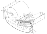
- FIG. 1A illustrates schematically the first embodiment of the adjusting mechanism for zonal control of an ink blade according to the invention, in which the segments of the ink blade are linearly moved, partly in an axonometric view and partly in cross-section perpendicular to the axis line of the ductor roller.
- FIG. 1B illustrates schematically an alternative configuration of the moving means in the first embodiment of the adjusting mechanism according to FIG. 1A, and in the same view as in FIG. 1 A.
- FIG. 2A illustrates schematically the second embodiment of the adjusting mechanism for zonal control of an ink blade according to the invention, in which the segments of the ink blade are moved by bending, in the same view as in FIG. 1 A.
- FIG. 2B illustrates a detail for altering the temperature of the bar in the moving means of the second embodiment of the adjusting mechanism according to FIG. 2A, in the area II of FIG. 1 A and shown in a larger scale.
- FIG. 3 illustrates schematically the third embodiment of the adjusting mechanism for zonal control of an ink blade according to the invention, in which the segments of the ink blade are moved by bending, in the same view as in FIGS. 1A and 2A.
- FIG. 4 illustrates the control of the ink layer thickness by the gap between the ductor roller and the edge of the ink blade in greater detail, in the area I of FIG. 1 A and in the same cross-section, but shown in a larger scale.
- FIG. 5 exemplifies the forces detected under driving of the ink blade until a contact between the edge of the ink blade and the ductor roller is created, and the play in the bearings of the ductor roller is at least partly pushed to its one boundary. These points are utilized for initializing of the positioning data.
- FIG. 6 illustrates the formation of ink streaks through the spacings between adjacent blade segments under their bending, in the same axonometric view as FIG. 1 A.
- FIG. 7 illustrates one possible configuration for the longitudinally gliding sides of the separate blade segments according to the invention, seen in the direction III of FIG. 1 A.
- Ink fountains whose principle components are shown in the figures, comprise an ink blade 2 and a ductor roller 4 .
- the ductor roller rotates to a direction R and the ink blade 2 has an inking edge 23 adjacent to the ductor roller 4 so that there is a variable and controlled gap 40 between the outer surface 5 of the ductor roller.
- the rotation direction R is downwards at the area of the inking edge 23
- the ink blade 2 is at least somewhat tilted as compared to horizontal so that the inking edge 23 is lower than the opposite edge area 33 . So an upwards open trough 30 is formed between the upper side 35 of the ink blade and the surface 5 of the ductor roller above the ink blade for receiving an amount of Ink as shown in FIG. 4 .
- the width G of the gap 40 defines the thickness B of the ink layer 29 below the inking edge 23 on the outer surface 5 of the ductor roller, and the ink layer is then removed from the ductor roller for further use in the printing press. This removing is not shown in the figures. Said width G of the gap 40 is altered and controlled by an adjusting mechanism discussed later in detail.
- the ductor roller has an axel 26 supported by bearings, not shown in the figures, in the a frame 10 of the printing press.
- the ink blade 2 and its optional support plate 36 are attached to the body 27 of the adjusting mechanism or to a separate body 27 .
- the adjusting mechanism according to the invention can be built in inside this body, as shown in FIG. 1A, or the adjusting mechanism according to the invention can be positioned inside a separate body 37 , as shown in FIGS. 2A and 3.
- These bodies 27 , 37 are also attached to the frame 10 —marked schematically by dashed pointed line in FIG. 1 A—in a way not shown in the figures.
- the adjusting mechanism comprising a plurality of moving means 1 in contact with the ink blade 2 and movable in a longitudinal direction P 1 , P 2 towards and away from said ductor roller 4 .
- a reference number 3 is used to indicate ink blade segments generally or any one of those ink blade segments, which segments are described later. Accordingly every ink blade segment, forming a zone, is moved and adjusted individually meaning zonal control of the ink blade.
- Each of the moving mean 1 according to the invention comprises at least one bar 6 of a shape memory material SMM having a length L at least partly in said longitudinal direction P 1 , P 2 .
- Each of the moving mean 1 according to the invention comprises also activating means 7 or 8 or 9 .
- the first end 11 of the bar or bars 6 is supported by the frame 10 through the body 27 or 37 , and the second end 12 of the bar or bars 6 is adapted to be in contact with the ink blade 2 in a point proximate to the inking edge 23 .
- the moving means 1 includes only one bar 6
- the moving means 1 includes several bars 6 connected parallel to each other. It is also possible to connect several bars in series with each other.
- the SMM bar or bars 6 are arranged so within the body 27 or 37 that the longitudinal dimension, i.e. length L can be freely change by an amount of ⁇ L.
- the second end 12 of the bar(s) is attached to a contact part 39 or a connecting part 24 , which is linearly movable in directions P 1 , P 2 inside and guided in sections 34 by the body 27 , 37 , as can be readily understood from the figures.
- Contact part 39 has a nose 28 which moves against the underside 25 of the ink blade segment 3 and bends K the same, whereupon the width G of gap 40 changes, as can be understood from FIGS. 2A and 3, because the blade segments 3 are springy and typically flexible.
- the connecting part 24 is rigidly attached to a blade segment 3 , whereupon the ink blade segments are moved in directions P 1 , P 2 when gliding between the support plate 36 and the foot 41 of the body 27 , whereupon the width G of gap 40 changes, as can be understood from FIGS. 1A and 4.
- the width G of gap 40 between the roller surface 5 and the inking edge 23 adjusts the thickness B of the Ink layer 29 on the surface 5 of the ductor roller 4 , which is visualized in FIG. 4 .
- an initial length L may be between 7 mm and 30 mm, whereupon the width G of the gap may change from 0 mm to 0.5 mm and vice versa.
- Said opposite directions P 1 , P 2 towards and away from said ductor roller surface 5 are such that they have a substantial partial vector in direction from the inking edge 23 to the centre line of the axel 26 when divided into two partial vectors perpendicular to each other.
- the bar 6 or bars are prepared from a first shape memory material SMM, which is a magnetic field sensitive material, and the activating means 7 are such that they provide a magnetic field strength H ⁇ H into said bar or bars.
- the magnetic field sensitive material is a nickel-gallium-manganese based alloy, or an iron-chromium-boron-silicon based alloy, or an iron-cobalt-titanium based alloy, or an iron-nickel-carbon based alloy, or an iron-manganese-nitrogen based alloy, or some other known or new alloy or material. These kind of materials are described e.g.
- Said activating means can be either a coil 7 around said bar(s) 6 , or a coil 7 around a core 13 of ferromagnetic material, ends 14 a , 14 b of which being in contact with said bar(s) 6 .
- a certain electrical voltage U and current I is fed to said coil 7 a definite magnetic field strength H are attained in said bar(s), which magnetic field strength causes s strain in said bar(s) altering the length L ⁇ L of the bar(s).
- the magnetic field strength H in said bar(s) 6 is changed by an amount ⁇ H, in general the magnetic field strength being H ⁇ H, whereupon the longitudinal dimension L ⁇ L of said bar(s) is altered thereby adjusting the position of the ink blade, i.e. the width G of the gap 40 .
- the bar 6 or bars are prepared from a second shape memory material SMM, which is a temperature sensitive material, and the activating means 8 are such that they provide a temperature T ⁇ T into said bar or bars.
- the temperature sensitive material is a titanium-nickel based alloy, which type of alloys are commercially available from several companies, e.g. under the name “Nitinol”. These types of alloys are generally called Shape Memory Alloys, and they perform a martensitic ⁇ austenitic —transformation under inverse changes of temperature, which transformation temperature can be selected to be anywhere between ⁇ 100° C. and +100° C.
- Said activating means can preferably be one or several Peltier-elements 8 with first active surface(s) 15 a against said bar(s) 6 and second active surface(s) 15 b connected to a thermal conductor 18 outside and thermally isolated, by thermal isolation 16 , from said bar(s).
- Peltier-elements are practical, because they are able to heat the bar(s) when the current I goes to one direction and to cool the bar(s) when the current I goes to opposite direction, the heating and cooling effect depending on the magnitude of the current.
- a higher or a lower electrical voltage/current U ⁇ U, I ⁇ I and/or an inverse electrical voltage/current ⁇ U, ⁇ I is fed into activating means 8 , in this case Peltier-elements, whereupon various thermal flows T ⁇ to or from said bar or momentarily no thermal flows are attained effecting various temperatures T ⁇ T in said bar(s). Accordingly a change ⁇ T of temperature in the bar(s) 6 is created, whereupon the longitudinal dimension L ⁇ L of said bar(s) is altered thereby adjusting the position of the ink blade, i.e. the width G of the gap 40 .
- second active surfaces 15 b of the Peltier-elements are e.g. in contact with thermal conductors 18 , which may be like fins used for cooling power semiconductors and commercially available, the room between the adjacent Peltier-elements and thermal conductors is filled with thermal isolation 16 , and the areas of the thermal conductors 18 facing away from the bar(s) 6 and opening into a cooling/heating channel 19 , through which a proper fluid is fed to exchange heat to one or the opposite direction.
- the bar or bars 6 are prepared from a third shape memory material SMM, which is a voltage sensitive material, especially an electrostrictive material or electrostrictor, and the activating means 9 are such that they provide an electrical voltage U ⁇ U and current I ⁇ U into said bar or bars.
- the electrostrictor materials are typically oxide ceramics having a “perovskite” structure, which is generally known definition.
- “Perovskite” compounds have the general formula ABO 3 , where the A cation is relatively large and of low valence—such as Ba 2+ , Sr 2+ , Ca 2+ , Pb 2+ , La 3+ , Sm 3+ , Nd 3+ , Bi 3+ , K 1+ ,etc. —and the B cation is relatively small and of high valence—such as Ti 4+ , Zr 4+ , Sn 4+ , W 6+ , Nb 5+ , Ta 5+ , Fe 3+ , Mn 3+ , Mg 2+ , Zn 2+ , Ni 2+ , etc.
- ABO 3 where the A cation is relatively large and of low valence—such as Ba 2+ , Sr 2+ , Ca 2+ , Pb 2+ , La 3+ , Sm 3+ , Nd 3+ , Bi 3+ , K 1+ ,etc.
- the B cation is relatively small
- a lead-magnesium-niobate ceramic material is an example, and the electrostrictive material is preferably a single-crystal electrostrictor material, whereupon a relatively high strain up to about 2% and medium output energy density per unit mass are the advantages of these kind of material.
- Concerning the magnitude of strain, i.e. the available change ⁇ L in a dimension L of the bar(s) it shall be noticed that its effect can be maximized by a proper geometry between the moving direction P 1 , P 2 of the moving means and the position and direction of the ink blade 2 in respect to the ductor roller 4 .
- With an additional mechanism like levers and/or with special configuration of the ink blade the dimensional change ⁇ L can be somewhat amplified, but then avoiding backlash totally is difficult.
- Magnetostrictive materials have a moderate strain of about 1500 ppm, and piezoelectric materials low strain of about 100-300 ppm, and so magnetostrictive and piezoelectric materials are at least not today practical for use as a SMM bar according to the invention. It shall be kept in mind that new materials are continuously developed, and so the situation can change in the future. The details of compositions, grain structures and phase transformations are not discussed, because the invention intends utilizing of Shape Memory Materials, not the Shape Memory Materials themselves.
- Said activating means are one or several electrical conductors 9 being in contact with said at least one bar 6 . When a controlled higher or lower electrical voltage U ⁇ U is fed through the activating means 9 , i.e.
- the ink blade 2 comprises a plurality of blade segments 3 a , 3 b , 3 c , 3 d . . . separate from and adjacent to each other, said blade segments 3 having inking edges 23 opposite to the surface 5 of the ductor roller 4 and longitudinal sides 22 , which are substantially perpendicular to said inking edges 23 and are in gliding contact with each other, as visualized in FIG. 7 .
- Each of the blade segments 3 are attached to, with a connecting part 24 , said at least one bar 6 in each one of said moving means as described above. Said bar or bars 6 are substantially parallel with the longitudinal sides 22 of said blade segments 3 a , 3 b , 3 c , 3 d . . .
- the longitudinal sides 22 are preferably provided with e.g. steps, as in FIG. 7, or grooves or the like, which has a configuration matching to each other on the opposite sides of adjacent blade segments 3 .
- the support plate 36 prohibits the excessive bending of the blade segments 3 and keeps the blade segments in a level.
- the blade segments 3 a , 3 b , 3 c , 3 d . . . can be quite stiff, because no bending is needed.
- the blade segments can also be springy and flexible. Because the blade segments 3 a , 3 b , 3 c , 3 d , 3 e . . . are independent from each other or separate, each of them is moved linearly in its entirety by its own moving means 1 in to adjust the gap 40 . There are at minimum ten blade segments and ten moving means 1 in an adjusting mechanism, but a typical amount of blade segments 3 and moving means 1 is in the order of sixty to hundred. The leak in the traditional construction of the blade segments 3 a , 3 b , 3 c , 3 d . . .
- FIG. 6 in which the segments are integral part of the ink blade 2 and formed by slits 45 having limited depth in a direction perpendicular to the inking edge 23 , is shown in FIG. 6 .
- a blade segment 3 is bend more than a neighbouring blade segment a lateral spacing 43 is formed between the sides 22 ′ of the blade segments, whereupon a leak of the Ink is caused which is noticed from streaks 44 of ink on the ductor roller or at least on printed sheet. So that configuration of the ink blade having separate and linearly movable blade segments, described in the beginning of this chapter, are preferred as compared to that configuration of the ink blade having integral and bending blade segments.
- the adjusting mechanism comprises also a control unit 20 supplying a controlled electrical voltage/current U, I into the activating means, or more in detail a higher or a lower electrical voltage/current U ⁇ U, I ⁇ I and/or an inverse electrical voltage/current ⁇ U, ⁇ I into activating means 7 ; 8 ; 9 for the bar(s) 6 , whereupon a magnetic field strength H or a temperature T or a voltage/current U, I in said bar is changed ⁇ H; ⁇ T; ⁇ U, ⁇ I altering a dimension L ⁇ L of said bar(s) thereby adjusting the position of the ink blade.
- the mechanism further comprises a first force sensor 31 positioned between said bar(s) 6 and said frame 10 for detecting the longitudinal compression force F present in the said bar(s).
- This step is performed prior to production/printing steps by feeding said electrical voltage/current into activating means 7 ; 8 ; 9 which drives the ink blade 2 in direction P 1 towards and against the ductor roller surface 5 .
- the mechanism further comprises a second force sensor 32 positioned between axel 26 of said ductor roller 4 and said frame 10 at that side of the ductor roller, which is opposite to the ink blade 2 .
- this second force sensor 32 With the aid of this second force sensor 32 the point, marked by ⁇ g in FIG. 5, in which the play in bearings of the axel 26 is eliminated by pushing the ductor roller 4 with the compression force F of the ink blade in a direction away from the ink blade 2 .
- the play in the bearings is the difference from point ⁇ 0 to point ⁇ g.
- the first signal S 1 received from said first force sensor and a second signal S 2 received from said second force sensor delivered to the control unit 20 are used in a predetermined manner for controlling the voltage U and/or the current I to be fed into said activating means 7 ; 8 ; 9 . In this way values for initializing the control unit 20 and the calculating means 21 are attained.
- the control unit 20 comprises calculating means 21 for determining the electrical voltage/current needed for the predetermined movement ⁇ L of said second end 12 .
- the first force sensor 31 , the second force sensor 32 can be of any type suitable for the purpose, and the control unit 20 , the calculating means 21 as well as said memory can include any electronic components and circuits suitable for the purpose. These types of sensors and electronic components as well as circuits are generally known, and so they are not described more in detail.
Landscapes
- Inking, Control Or Cleaning Of Printing Machines (AREA)
- Heating, Cooling, Or Curing Plastics Or The Like In General (AREA)
- Screen Printers (AREA)
- Coating Apparatus (AREA)
Applications Claiming Priority (3)
| Application Number | Priority Date | Filing Date | Title |
|---|---|---|---|
| EP01660097A EP1260365B1 (de) | 2001-05-17 | 2001-05-17 | Einstellmechanismus für Farbrakel |
| EP01660097.5 | 2001-05-17 | ||
| EP01660097 | 2001-05-17 |
Publications (2)
| Publication Number | Publication Date |
|---|---|
| US20020195011A1 US20020195011A1 (en) | 2002-12-26 |
| US6681698B2 true US6681698B2 (en) | 2004-01-27 |
Family
ID=8183628
Family Applications (1)
| Application Number | Title | Priority Date | Filing Date |
|---|---|---|---|
| US10/150,647 Expired - Fee Related US6681698B2 (en) | 2001-05-17 | 2002-05-16 | Ink blade adjusting mechanism having shape memory material actuator |
Country Status (4)
| Country | Link |
|---|---|
| US (1) | US6681698B2 (de) |
| EP (1) | EP1260365B1 (de) |
| AT (1) | ATE292018T1 (de) |
| DE (1) | DE60109754T2 (de) |
Cited By (2)
| Publication number | Priority date | Publication date | Assignee | Title |
|---|---|---|---|---|
| US20040145435A1 (en) * | 2002-10-23 | 2004-07-29 | Honda Motor Co., Ltd. | Actuator |
| US20070181023A1 (en) * | 2004-04-22 | 2007-08-09 | Daniel Baertschi | Ink fountain for a printing machine |
Families Citing this family (12)
| Publication number | Priority date | Publication date | Assignee | Title |
|---|---|---|---|---|
| FI118420B (fi) * | 2006-03-21 | 2007-11-15 | Veslatec Oy | Suihkuttava kostutusjärjestelmä painokoneissa |
| DE102007053596A1 (de) * | 2007-11-09 | 2009-05-14 | Manroland Ag | Positionierantriebsanordnung einer Druckmaschine |
| KR101005235B1 (ko) | 2008-06-30 | 2010-12-31 | 한양대학교 산학협력단 | 액체에 부분적으로 잠긴 고속회전 롤러 위의 액막 두께예측방법 |
| DE102009058851A1 (de) | 2009-12-18 | 2011-06-22 | Heidelberger Druckmaschinen AG, 69115 | Verfahren zum Dosieren einer Farbschichtdicke auf einer Farbkastenwalze einer Druckmaschine |
| CN102328505A (zh) * | 2011-07-29 | 2012-01-25 | 浙江伟博包装印刷品有限公司 | 一种可伸缩活动杆保护装置 |
| US11034145B2 (en) | 2016-07-20 | 2021-06-15 | Ball Corporation | System and method for monitoring and adjusting a decorator for containers |
| MX2019000614A (es) | 2016-07-20 | 2019-07-04 | Ball Corp | Sistema y metodo para alinear un entintador de un decorador. |
| EP3740383A4 (de) * | 2018-01-19 | 2021-10-20 | Ball Corporation | System und verfahren zur überwachung und einstellung eines dekorators für behälter |
| CN110001185B (zh) * | 2019-04-08 | 2021-04-13 | 杭州前景企业形象策划有限公司 | 一种柔版印刷机的印刷装置 |
| CN110667250B (zh) * | 2019-08-23 | 2021-10-01 | 北京英格条码技术发展有限公司 | 一种标签印刷机的压印结构 |
| CN111823708B (zh) * | 2020-08-19 | 2023-12-08 | 静宁县恒达有限责任公司 | 一种柔版印刷机超磁致伸缩材料刮墨刀进给机构 |
| DE102022002852A1 (de) | 2022-07-26 | 2024-02-01 | Technische Universität Chemnitz, Körperschaft des öffentlichen Rechts | Einrichtung zum Abstreifen von aufgebrachten überschüssigen Material mit einer Rakel und Verwendung einer Rakel |
Citations (11)
| Publication number | Priority date | Publication date | Assignee | Title |
|---|---|---|---|---|
| US4119836A (en) | 1975-11-26 | 1978-10-10 | Kakogawa Plastics Kabushiki Kaisha | Heat-controlled doctor knife |
| DE2951653A1 (de) | 1979-12-21 | 1981-07-02 | M.A.N.- Roland Druckmaschinen AG, 6050 Offenbach | Vorrichtung zum dosieren von farbe auf der farbkastenwalze eines farbwerks fuer druckmaschinen |
| US4581994A (en) * | 1983-07-11 | 1986-04-15 | M.A.N.-Roland Druckmaschinen Aktiengesellschaft | Ink metering device for a printing press |
| US5052297A (en) | 1989-10-23 | 1991-10-01 | Patric Albiez | Adjustment mechanism for sectionalized doctor blades |
| DE9112926U1 (de) | 1991-10-17 | 1991-12-05 | Heidelberger Druckmaschinen Ag, 6900 Heidelberg | Einrichtung zum zonenweisen Dosieren eines flüssigen Mediums auf einer Walze einer Druckmaschine |
| WO1999045631A2 (en) | 1998-03-03 | 1999-09-10 | Adaptamat, Adaptive Materials Technology Oy | Actuators and apparatus |
| US5958154A (en) | 1996-08-19 | 1999-09-28 | Massachusetts Institute Of Technology | High-strain, magnetic field-controlled actuator materials |
| US5983798A (en) * | 1998-05-15 | 1999-11-16 | Tokyo Kikai Seisakusho, Ltd | Doctor blade apparatus |
| US6062139A (en) * | 1998-09-08 | 2000-05-16 | Tokyo Kikai Seisakusho, Ltd. | Device for adjusting ink supply gap for ink fountain apparatus |
| US6157101A (en) | 1995-07-11 | 2000-12-05 | Ullakko; Kari M. | Method for producing motion and force by controlling the twin structure orientation of a material and its uses |
| US20020088358A1 (en) * | 2000-11-10 | 2002-07-11 | Walter Hofheinz | Ink metering system in a printing press |
-
2001
- 2001-05-17 AT AT01660097T patent/ATE292018T1/de active
- 2001-05-17 EP EP01660097A patent/EP1260365B1/de not_active Expired - Lifetime
- 2001-05-17 DE DE60109754T patent/DE60109754T2/de not_active Expired - Lifetime
-
2002
- 2002-05-16 US US10/150,647 patent/US6681698B2/en not_active Expired - Fee Related
Patent Citations (13)
| Publication number | Priority date | Publication date | Assignee | Title |
|---|---|---|---|---|
| US4119836A (en) | 1975-11-26 | 1978-10-10 | Kakogawa Plastics Kabushiki Kaisha | Heat-controlled doctor knife |
| DE2951653A1 (de) | 1979-12-21 | 1981-07-02 | M.A.N.- Roland Druckmaschinen AG, 6050 Offenbach | Vorrichtung zum dosieren von farbe auf der farbkastenwalze eines farbwerks fuer druckmaschinen |
| US4328748A (en) | 1979-12-21 | 1982-05-11 | M.A.N.-Roland Druckmaschinen Aktiengesellschaft | Arrangement for metering ink on the fountain roller of a printing press |
| US4581994A (en) * | 1983-07-11 | 1986-04-15 | M.A.N.-Roland Druckmaschinen Aktiengesellschaft | Ink metering device for a printing press |
| EP0425432B1 (de) | 1989-10-23 | 1994-06-29 | Patric Albiez | Stellmechanismus für in Zonen aufgeteilte Rakel |
| US5052297A (en) | 1989-10-23 | 1991-10-01 | Patric Albiez | Adjustment mechanism for sectionalized doctor blades |
| DE9112926U1 (de) | 1991-10-17 | 1991-12-05 | Heidelberger Druckmaschinen Ag, 6900 Heidelberg | Einrichtung zum zonenweisen Dosieren eines flüssigen Mediums auf einer Walze einer Druckmaschine |
| US6157101A (en) | 1995-07-11 | 2000-12-05 | Ullakko; Kari M. | Method for producing motion and force by controlling the twin structure orientation of a material and its uses |
| US5958154A (en) | 1996-08-19 | 1999-09-28 | Massachusetts Institute Of Technology | High-strain, magnetic field-controlled actuator materials |
| WO1999045631A2 (en) | 1998-03-03 | 1999-09-10 | Adaptamat, Adaptive Materials Technology Oy | Actuators and apparatus |
| US5983798A (en) * | 1998-05-15 | 1999-11-16 | Tokyo Kikai Seisakusho, Ltd | Doctor blade apparatus |
| US6062139A (en) * | 1998-09-08 | 2000-05-16 | Tokyo Kikai Seisakusho, Ltd. | Device for adjusting ink supply gap for ink fountain apparatus |
| US20020088358A1 (en) * | 2000-11-10 | 2002-07-11 | Walter Hofheinz | Ink metering system in a printing press |
Non-Patent Citations (3)
| Title |
|---|
| Kakeshita and Shimizu, "Magnetoelastic Martensitic Transformation", Scripta Metallurgica, vol. 19, pp. 973-976, 1985. |
| Kyprianidis et al., "Magnetic phase transitions in FeCrBSi alloys", Journal of Magnetism and Magnetic Materials 161 (1996) 203-208. |
| Webster, "Magnetic order and phase transformation in Ni2MnGa", Philosophical magazine B, 1984, vol. 49, No. 3, 295-310. |
Cited By (3)
| Publication number | Priority date | Publication date | Assignee | Title |
|---|---|---|---|---|
| US20040145435A1 (en) * | 2002-10-23 | 2004-07-29 | Honda Motor Co., Ltd. | Actuator |
| US6803846B2 (en) * | 2002-10-23 | 2004-10-12 | Honda Motor Co., Ltd. | Actuator |
| US20070181023A1 (en) * | 2004-04-22 | 2007-08-09 | Daniel Baertschi | Ink fountain for a printing machine |
Also Published As
| Publication number | Publication date |
|---|---|
| DE60109754D1 (de) | 2005-05-04 |
| ATE292018T1 (de) | 2005-04-15 |
| US20020195011A1 (en) | 2002-12-26 |
| DE60109754T2 (de) | 2006-02-09 |
| EP1260365A1 (de) | 2002-11-27 |
| EP1260365B1 (de) | 2005-03-30 |
Similar Documents
| Publication | Publication Date | Title |
|---|---|---|
| US6681698B2 (en) | Ink blade adjusting mechanism having shape memory material actuator | |
| DE69114392T2 (de) | Gerät zum Zentrieren eines Wandlers über einer Spur einer Magnetplatte in einem Speicherplattensystem. | |
| DE69412805T2 (de) | Drucker mit einem beweglichen Druckkopf | |
| JP6813224B2 (ja) | 造形材料吐出ヘッド | |
| US4328748A (en) | Arrangement for metering ink on the fountain roller of a printing press | |
| DE69408001T2 (de) | Verfahren und Vorrichtung zum Erwärmen der Tinte in einem Farbstrahldruckkopf | |
| US3967092A (en) | Electrothermal print head | |
| EP2366553B1 (de) | Druckvorrichtung und druckverfahren | |
| EP2629979B1 (de) | Druckvorrichtung | |
| JPH0156649B2 (de) | ||
| DE2406613B2 (de) | Thermo-druckvorrichtung | |
| SE470182B (sv) | Inloppslåda för en pappersmaskin | |
| CA1134201A (en) | Variable tape advance imprint marker | |
| JPH0796293B2 (ja) | 印刷機のインク供給量調整装置 | |
| EP4347301A1 (de) | Transporteinrichtung und verfahren zum betreiben einer transporteinrichtung | |
| US4130752A (en) | Electrothermal print head | |
| DE2608301C2 (de) | Vorrichtung zur Regelung des Abstandes eines Druckkopfes von einem Aufzeichnungsträger | |
| DE60133358T2 (de) | Druckverfahren und für die Durchführung des Verfahrens geeigneter Drucker | |
| US4559874A (en) | Ink metering system in letterpress and offset printing machines | |
| FI69597C (fi) | Matrisskrivare med automatisk reglering av tryckhuvudet | |
| US4709635A (en) | Fluid metering method and apparatus | |
| EP0631876A2 (de) | Thermodruckknopf | |
| DE60115152T2 (de) | Zeilenthermokopf und Erregungsteuerungsverfahren | |
| EP1177895A2 (de) | Prägemaschine für Prägefolien | |
| DE102007053596A1 (de) | Positionierantriebsanordnung einer Druckmaschine |
Legal Events
| Date | Code | Title | Description |
|---|---|---|---|
| AS | Assignment |
Owner name: VESLATEC OY, FINLAND Free format text: ASSIGNMENT OF ASSIGNORS INTEREST;ASSIGNORS:WEHMEIER, HANS-WILL;SAARNAHO, OLLI;REEL/FRAME:013214/0278 Effective date: 20020520 |
|
| FPAY | Fee payment |
Year of fee payment: 4 |
|
| FPAY | Fee payment |
Year of fee payment: 8 |
|
| REMI | Maintenance fee reminder mailed | ||
| LAPS | Lapse for failure to pay maintenance fees | ||
| STCH | Information on status: patent discontinuation |
Free format text: PATENT EXPIRED DUE TO NONPAYMENT OF MAINTENANCE FEES UNDER 37 CFR 1.362 |
|
| STCH | Information on status: patent discontinuation |
Free format text: PATENT EXPIRED DUE TO NONPAYMENT OF MAINTENANCE FEES UNDER 37 CFR 1.362 |
|
| FP | Lapsed due to failure to pay maintenance fee |
Effective date: 20160127 |