US6679092B2 - Automobile sheet metal surface correcting equipment - Google Patents
Automobile sheet metal surface correcting equipment Download PDFInfo
- Publication number
- US6679092B2 US6679092B2 US10/057,044 US5704402A US6679092B2 US 6679092 B2 US6679092 B2 US 6679092B2 US 5704402 A US5704402 A US 5704402A US 6679092 B2 US6679092 B2 US 6679092B2
- Authority
- US
- United States
- Prior art keywords
- air
- housing
- piston
- sheet metal
- metal surface
- Prior art date
- Legal status (The legal status is an assumption and is not a legal conclusion. Google has not performed a legal analysis and makes no representation as to the accuracy of the status listed.)
- Expired - Lifetime
Links
- 239000002184 metal Substances 0.000 title claims abstract description 123
- 230000007246 mechanism Effects 0.000 claims abstract description 63
- 230000002093 peripheral effect Effects 0.000 claims description 12
- 230000008859 change Effects 0.000 claims description 6
- 238000005555 metalworking Methods 0.000 abstract description 8
- 238000010276 construction Methods 0.000 description 4
- 238000003780 insertion Methods 0.000 description 4
- 230000037431 insertion Effects 0.000 description 4
- 230000008901 benefit Effects 0.000 description 3
- 238000011109 contamination Methods 0.000 description 3
- 239000007769 metal material Substances 0.000 description 3
- 230000035939 shock Effects 0.000 description 2
- 206010039203 Road traffic accident Diseases 0.000 description 1
- 230000001747 exhibiting effect Effects 0.000 description 1
- 238000012986 modification Methods 0.000 description 1
- 230000004048 modification Effects 0.000 description 1
- 230000000452 restraining effect Effects 0.000 description 1
- 238000000926 separation method Methods 0.000 description 1
- 125000006850 spacer group Chemical group 0.000 description 1
Images


Classifications
-
- B—PERFORMING OPERATIONS; TRANSPORTING
- B60—VEHICLES IN GENERAL
- B60S—SERVICING, CLEANING, REPAIRING, SUPPORTING, LIFTING, OR MANOEUVRING OF VEHICLES, NOT OTHERWISE PROVIDED FOR
- B60S5/00—Servicing, maintaining, repairing, or refitting of vehicles
-
- B—PERFORMING OPERATIONS; TRANSPORTING
- B21—MECHANICAL METAL-WORKING WITHOUT ESSENTIALLY REMOVING MATERIAL; PUNCHING METAL
- B21D—WORKING OR PROCESSING OF SHEET METAL OR METAL TUBES, RODS OR PROFILES WITHOUT ESSENTIALLY REMOVING MATERIAL; PUNCHING METAL
- B21D1/00—Straightening, restoring form or removing local distortions of sheet metal or specific articles made therefrom; Stretching sheet metal combined with rolling
- B21D1/12—Straightening vehicle body parts or bodies
-
- Y—GENERAL TAGGING OF NEW TECHNOLOGICAL DEVELOPMENTS; GENERAL TAGGING OF CROSS-SECTIONAL TECHNOLOGIES SPANNING OVER SEVERAL SECTIONS OF THE IPC; TECHNICAL SUBJECTS COVERED BY FORMER USPC CROSS-REFERENCE ART COLLECTIONS [XRACs] AND DIGESTS
- Y10—TECHNICAL SUBJECTS COVERED BY FORMER USPC
- Y10S—TECHNICAL SUBJECTS COVERED BY FORMER USPC CROSS-REFERENCE ART COLLECTIONS [XRACs] AND DIGESTS
- Y10S72/00—Metal deforming
- Y10S72/705—Vehicle body or frame straightener
Definitions
- This invention relates to an equipment for correcting a surface of a sheet metal material for an automobile or an automobile sheet metal surface correcting equipment adapted to push or pull a surface of a sheet metal material to correct roughness or ruggedness of the surface such as deformation thereof, strain thereof or the like, and more particularly to an automobile sheet metal surface correcting equipment which is adapted to actuate an impact wrench mechanism by means of compressed air fed from an air supply means such as, for example, an air compressor or the like thereto to retractably operate a piston arranged in a cylinder thereof, to thereby correct ruggedness of the automobile sheet metal surface.
- an air supply means such as, for example, an air compressor or the like
- FIGS. 27 (A), 27 (B) and 29 An equipment which has been conventionally used for repairing roughness or ruggedness generated on a surface of a sheet metal material of an automobile due to a traffic accident or the like is constructed in such a manner as shown in either FIGS. 27 (A), 27 (B) and 29 or FIGS. 28 (A), 28 (B) and 30 .
- the conventional equipment generally designated at reference numeral 300 in FIGS.
- 27 (A), 27 (B) and 29 is constructed in such a manner that a handle 311 of a hydraulic pump 310 connected through a high pressure hose 303 to a cylinder 301 in which a piston 302 is movably received is operated to extend the piston 302 from the cylinder 301 , resulting in an inward projection 350 generated on a sheet metal surface of an automobile 200 being pushed out through an attachment 155 attached to a distal end of the piston 302 .
- the conventional equipment generally designated at reference numeral 400 in FIGS.
- 28 (A), 28 (B) and 30 is so constructed that a handle 311 of a hydraulic pump 310 connected through a high pressure hose 303 to a cylinder 401 having a piston 402 movably received therein is operated to retract the piston 402 into the cylinder 401 , resulting in a depression 351 generated on a metal sheet surface of an automobile 200 being forced out.
- Another disadvantage of the prior art is that there is a likelihood of causing oil to leak from the hydraulic pump during sheet metal working, leading to contamination of the automobile with the oil.
- the prior art is highly laborious because of requiring two workers or one for positioning the distal end of the piston on a portion of the metal sheet surface to be corrected and the other for carrying out pressurizing operation by means of the hydraulic pump.
- the present invention has been made in view of the foregoing disadvantages of the prior art.
- an object of the present invention to provide an automobile sheet metal surface correcting equipment which is capable of solely selectively carrying out pushing or pulling of a sheet metal surface depending on properties of the sheet metal surface.
- an automobile sheet metal surface correcting equipment includes a housing having an air flow path means switchably arranged therein, an air introduction means provided therein with air introduction passages for introducing compressed air into the housing therethrough, an impact wrench mechanism arranged in the housing and actuated by means of compressed air fed through the air introduction means into the housing, a screw bolt having rotating force applied thereto from the impact wrench mechanism, and a piston mechanism including a cylinder and a piston movably arranged in the cylinder in a retractable manner in association with rotation of the screw bolt, whereby the air flow path means in the housing is changed over to retractably move the piston of the piston mechanism, resulting in a metal sheet surface being corrected.
- the impact wrench mechanism includes an air motor actuated by means of compressed air fed to the housing and an impact wrench actuated by the air motor.
- a rotation direction changing-over valve is arranged for changing over the air flow path means, to thereby change over a direction of rotation of the air motor of the impact wrench mechanism.
- the air flow path means includes a first air flow path and a second air flow path which are changed over by the rotation direction changing-over valve.
- holding bolts are arranged for mounting a cover means on each of end surfaces of the housing to close the end surface, whereby the air flow path means in the housing is changed over during actuation of the impact wrench mechanism to actuate the piston of the piston mechanism, resulting in correcting the sheet metal surface.
- holding bolts are arranged for mounting a cover means on each of end surfaces of the housing to close the end surface, whereby a direction of rotation of the air motor is changed over to actuate the piston of the piston mechanism, to thereby correct the sheet metal surface.
- the air introduction means includes a handle having the air introduction passages formed therein.
- the handle is arranged above the housing.
- the housing includes a first receiving portion and a second receiving portion.
- the first receiving portion has the impact wrench mechanism received therein.
- the screw bolt includes a bolt head.
- the second receiving portion has the bolt head of the screw bolt received therein.
- the housing has a first opening formed on one of the end surfaces thereof and a second opening formed on the other of the end surfaces thereof. The first opening is closed with a first cover means and the second opening is closed with a second cover means.
- the first cover means is formed on an inner surface thereof with a pair of air passages constituting a part of the air flow path means.
- the housing has a cylindrical hole formed above the first receiving portion to fit a bushing therein, wherein the bushing is formed at a lower portion thereof on a rear right side thereof with a first air outlet hole and at a lower portion thereof on a front left side thereof with a second air outlet hole.
- the housing has two air passages formed on both sides of the cylindrical hole. One of the air passages is arranged so as to communicate with one air passage of the first cover means and the first air outlet hole of the bushing, and the other of the air passage is arranged so as to communicate with the other air passage of the first cover means and the second air outlet hole of the bushing.
- the housing has a step formed on an upper surface thereof and the air introduction means includes a handle formed with the air introduction passage.
- the step of the housing is formed with an air introduction hole so as to communicate with the air introduction passage of the handle.
- the step of the housing is formed at corners thereof with threaded holes.
- the handle is airtightly fixed at a proximal end thereof on the step of the housing by means of bolts.
- the air introduction means includes a handle, an air regulator arranged on a proximal end of the handle, an air valve arranged on a central portion of a bottom surface of the handle, a switch lever disposed so as to operate the air valve, a control pin for selectively controlling movement of the switch lever, and a stopper pivotally supported in a cutout formed at a free end of the switch lever so as to be raised therein.
- the air valve is rendered open by operating the switch lever toward the bottom surface of the handle. Control of movement of the switch lever by the control pin is carried out in order to maintain such an open state of the air valve.
- the air valve includes a valve body.
- the valve body is disposed in a valve chest arranged between the air introduction passages.
- the valve body of the air valve when the switch lever is operated to upwardly push a lower end of the air valve while abuttedly contacting it with an upper surface of the switch lever, is raised from a valve seat arranged in the valve chest, resulting in the air valve being rendered open, so that the air introduction passages may be permitted to communicate with each other, to thereby permit compressed air introduced to flow into the housing through the air introduction hole formed on the upper surface of the housing.
- the rotation direction changing-over valve is projected at both ends thereof from the bushing.
- the piston mechanism includes the piston, the cylinder and a piston guide member.
- the piston is constructed into a hollow structure, resulting in being provided therein with a central hole so as to extend in a longitudinal direction thereof.
- the central hole of the piston is formed with female threads with which male threads of the screw bolt are threadedly engaged.
- the piston is formed on an outer peripheral surface thereof with an elongated guide groove for guiding the piston guide member and the guide groove is arranged so as to extend in the longitudinal direction of the piston.
- the first cover means, housing and second cover means are integrally connected to each other by means of the holding bolts inserted through corners of the housing.
- the holding bolts each are threadedly engaged at a distal end thereof with each of the female screws formed in the second cover member.
- FIG. 1 is a perspective view showing an embodiment of an automobile sheet metal surface correcting equipment according to the present invention
- FIG. 2 is a front elevation view of the automobile sheet metal surface correcting equipment shown in FIG. 1;
- FIG. 3 is a rear elevation view of the automobile sheet metal surface correcting equipment shown in FIG. 1;
- FIG. 4 is a bottom view of the automobile sheet metal surface correcting equipment shown in FIG. 1;
- FIG. 5 is a schematic right side elevation view of the automobile sheet metal surface correcting equipment shown in FIG. 1 in which a switch lever is kept raised and a rotational direction changing-over valve is kept forwardly forced out;
- FIG. 6 is a schematic right side elevation view of the automobile sheet metal surface correcting equipment shown in FIG. 1 in which a switch lever is kept raised and a rotational direction changing-over valve is kept forced out rearwardly of a position thereof shown in FIG. 5;
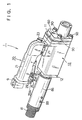
- FIG. 7 is a left side elevation view of the automobile sheet metal surface correcting equipment shown in FIG. 1;
- FIG. 8 is a perspective view showing a cap which serves as a first cover means for covering or closing an opening formed on a rear end surface of a housing of the automobile sheet metal surface correcting equipment shown in FIG. 1;
- FIG. 9 is a partially cutaway schematic perspective view in section of the automobile sheet metal surface correcting equipment of FIG. 1, which shows an internal structure of the automobile sheet metal surface correcting equipment;
- FIG. 10 is a sectional view taken along line X—X of FIG. 5, which shows flow of compressed air obtained when an air motor is rotated normally or in a counter-clockwise direction to advance a piston from an interior of a cylinder;
- FIG. 11 is a sectional view taken along line Y—Y of FIG. 6, which shows flow of compressed air obtained when an air motor is rotated reversely or in a clockwise direction to retract a piston into a cylinder;
- FIG. 12 is a perspective view of the automobile sheet metal surface correcting equipment shown in FIG. 1, in which a piston is kept extended or advanced;
- FIG. 13 is a front elevation view of the automobile sheet metal surface correcting equipment shown in FIG. 1, in which a piston is kept extended;
- FIG. 14 is a rear elevation view of the automobile sheet metal surface correcting equipment shown in FIG. 1, in which a piston is kept extended;
- FIG. 15 is a schematic perspective view showing an internal structure of the automobile sheet metal surface correcting equipment of FIG. 1, in which a piston is kept extended;
- FIG. 16 is an exploded perspective view showing components of the automobile sheet metal surface correcting equipment of FIG. 1;
- FIG. 17 is an exploded perspective view showing components of each of a housing, an air suction means, a piston mechanism and a rotation direction changing-over valve incorporated in the automobile sheet metal surface correcting equipment of FIG. 1;
- FIG. 18 is an exploded perspective view showing components of an impact wrench mechanism incorporated in the automobile sheet metal surface correcting equipment of FIG. 1;
- FIG. 19 is a front elevation view showing the automobile sheet metal surface correcting equipment of FIG. 1 having an attachment attached thereto;
- FIG. 20 is a front elevation view showing the automobile sheet metal surface correcting equipment of FIG. 1 having an attachment attached thereto, in which a switch lever is locked by means of a control pin after being operated and a piston is kept extended;
- FIG. 21 is a schematic plan view showing correcting operation for forcing out a depression of a quarter panel of a trunk room of an automobile by means of the automobile sheet metal surface correcting equipment of FIG. 1 having an attachment attached thereto;
- FIG. 22 is a perspective view showing examples of an attachment which may be attached to the automobile sheet metal surface correcting equipment of FIG. 1 as desired;
- FIG. 23 is a front elevation view showing the automobile sheet metal surface correcting equipment of FIG. 1 having an attachment attached thereto, in which a switch lever is locked by means of a control pin after being operated and a piston is kept extended;
- FIG. 24 is a front elevation view showing the automobile sheet metal surface correcting equipment of FIG. 1 having an attachment attached thereto, in which a switch lever is locked by means of a control pin after being operated and a piston is retracted into a cylinder;
- FIG. 25 is a schematic plan view showing correcting operation for pulling out a depression of a door panel of an automobile by means of the automobile sheet metal surface correcting equipment of FIG. 1 having an attachment attached thereto;
- FIG. 26 is a schematic plan view showing correcting operation in which a depression of a door panel of an automobile has been pulled out by means of the automobile sheet metal surface correcting equipment of FIG. 1 having an attachment attached thereto;
- FIG. 27 (A) is a perspective view showing a conventional automobile sheet metal surface correcting equipment while keeping a piston from being projected or advanced;
- FIG. 27 (B) is a perspective view of the conventional automobile sheet metal surface correcting equipment shown in FIG. 27 (A) after the piston is projected or advanced;
- FIG. 28 (A) is a perspective view showing another automobile sheet metal surface correcting equipment while keeping a piston projected or advanced;
- FIG. 28 (B) is a perspective view of the conventional automobile sheet metal surface correcting equipment shown in FIG. 28 (A) while keeping the piston retracted;
- FIG. 29 is a schematic plan view showing correcting operation for forcing out an inward projection or depression of a quarter panel of a trunk room of an automobile by means of the conventional automobile sheet metal surface correcting equipment of FIGS. 27 (A) and 27 (B); and
- FIG. 30 is a schematic plan view showing correcting operation for drawing or pulling out a depression of a quarter panel of a trunk room of an automobile by means of the conventional automobile sheet metal surface correcting equipment of FIGS. 28 (A) and 28 (B).
- FIGS. 1 to 26 illustrate an embodiment of an automobile sheet metal surface correcting equipment according to the present invention.
- An automobile sheet metal surface correcting equipment of the illustrated which is generally designated at reference numeral 1 includes a housing 10 , an air introduction means 20 which is provided therein with air introduction passages for introducing compressed air into the housing 10 therethrough, an impact wrench mechanism 30 arranged in the housing 10 and actuated by means of compressed air fed through the air introduction means 20 into the housing 10 , a rotation direction changing-over valve 60 for changing over a direction of rotation of an air motor constituting the impact wrench mechanism 30 , a screw bolt 70 having revolving force applied thereto from the impact wrench mechanism 30 , a piston mechanism 80 including a cylinder 86 and a piston 81 movably arranged in the cylinder 86 so as to be retractable with respect to the cylinder 86 , and holding bolts 90 inserted through corners of the housing 10 to mount first and second cover means 11 and 12 for covering or closing openings 10 A and 10 B formed on both end surfaces of the housing 10 on the housing 10 .
- the housing 10 is formed therein with two air passages or first and second air passages, which are changed over by the rotation direction changing-over valve 60 to retractably move the piston 81 of the piston mechanism 81 , to thereby selectively push or pull a sheet metal surface, leading to correction of the sheet metal surface.
- the housing 10 is formed in a rear half thereof with a first receiving portion 13 A of a large diameter and in a front half thereof with a second receiving portion 13 B of a small diameter, as shown in FIGS. 10, 11 and 17 .
- the first receiving portion 13 A of the housing 10 has the impact wrench mechanism 30 and a guide member 35 received therein and the opening 10 A formed on one of the end surfaces of the housing 10 is covered with a cap which acts as the first cover means 11 , as shown in FIG. 16 .
- the second receiving portion 13 B of the housing 10 has a bolt head 71 of the screw bolt 70 , a spacer 101 , thrust bearings 102 A and 102 B for ensuring smooth rotation of the screw bolt 70 , and bolt receivers 103 A and 103 B received therein.
- the opening 10 B formed on the other end surface of the housing 10 is covered with a cover acting as the second cover means 12 , as shown in FIG. 16 .
- the first cover means or cap 11 is formed in an inner surface thereof with a pair of laterally arranged air passages 11 A and 11 B which cooperate with each other to constitute a part of an air flow path, as shown in FIGS. 5, 6 and 8 .
- the housing 10 is formed at a portion thereof positioned above the first receiving portion 13 A with a cylindrical hole 14 so as to extend in a longitudinal or axial direction thereof, in which a bushing 65 is fitted. Also, the housing 10 is formed with a pair of air passages 15 and 16 so as to be positioned on both sides of the cylindrical hole 14 .
- the air passage 15 is arranged so as to communicate with an air outlet hole 67 formed at a lower portion of the bushing 65 positioned on a rear right side thereof when the bushing 65 is fitted in the cylindrical hole 14 of the housing 10 .
- the air passage 16 is adapted to communicate with an air outlet hole 68 formed at a lower portion of the bushing 65 on a front left side thereof when the fitting is made.
- the air passages 15 and 16 of the housing 10 are arranged so as to communicate with the air passages 11 A and 11 B of the cap 11 , respectively, when the cap 11 is mounted on the housing 10 .
- the air introduction means 20 includes a handle 21 , which is formed with an air introduction passage 21 C.
- the housing 10 is provided on an upper surface thereof with a step 10 C, which is formed at a central portion thereof with an air introduction hole 17 so as to communicate with the air introduction passage 21 C of the handle 21 of the air introduction means 20 when the air introduction means 20 is connected to the housing 10 as described hereinafter.
- the housing 10 is formed on a bottom surface thereof with an exhaust hole 18 in correspondence to an air outlet holes 43 A (FIG. 18) formed on a bottom of the cylinder 43 , which will be described hereinafter.
- the upper step 10 C of the housing 10 is formed at corners thereof with threaded holes 19 .
- the handle 21 of the air introduction means 20 is placed on the step 10 C of the housing 10 and then fixed thereon by threadedly inserting bolts 95 into the threaded holes 19 while ensuring airtight connection therebetween.
- the air introduction means 20 includes the above-described handle 21 , an air regulator 23 arranged on a proximal end of the handle 21 , an air valve 24 arranged on a central portion of a bottom surface of the handle 21 , a switch lever 25 disposed on the bottom surface of the handle 21 so as to operate the air valve 24 , a control pin 26 for selectively restraining or controlling movement of the switch lever 25 , and a stopper 27 pivotally supported in a cutout 25 A (FIGS. 1 and 9) formed at a free end of the switch lever 25 so as to be raised therein.
- the air valve 24 is rendered open by moving or pulling the switch lever 25 toward the bottom surface of the handle 21 .
- Reference numeral 9 designates a connector which is connected to the free end of the handle 21 and through which an air hose is connected to the handle 21 .
- the handle 21 is formed therein with the air introduction passage 21 C, as well as air introduction passages 21 A and 21 B, through which compressed air is introduced into the housing 10 , as shown in FIGS. 9 to 11 .
- the air regulator 23 includes a knob 23 A rotatably attached thereto and is formed therein with a flow control hole 23 B (FIG. 9 ).
- the air regulator 23 is so constructed that rotation of the knob 23 A varies a degree of threaded engagement between the air regulator 23 and the housing 21 , to thereby adjust a degree of opening of the flow control hole 23 B, resulting in controlling a flow rate of compressed air which flows through the air introduction passage 21 C.
- the air valve 24 includes a valve body 24 A (FIG. 9 ), which is disposed in a valve chest 22 arranged between the air introduction passages 21 A and 21 B.
- a valve body 24 A (FIG. 9 )
- the switch lever 25 is operated to upwardly push a lower end of the air valve 24 while abuttedly contacting it with an upper surface of the switch lever 25
- the valve body 24 A of the air valve 24 is raised from a valve seat in the valve chest 22 , resulting in the air valve 24 being open, so that the air introduction passages 21 A, 21 B and 21 C may be permitted to communicate with each other, to thereby permit compressed air introduced into the handle to flow into the housing 10 through the air introduction hole 17 (FIGS.
- the switch lever 25 is pivotally supported at a proximal end thereof on a short pin 28 inserted through insertion holes formed at a central portion of the handle 21 positioned on a bottom side thereof, as shown in FIG. 2 .
- the control pin 26 is inserted through pin insertion holes 29 A (FIGS. 1 and 17) formed via a pair of projections 29 provided on a lower surface of the free end of the handle 21 so as to downwardly extend therefrom, to thereby control or regulate movement of the switch lever 25 raised.
- the impact wrench mechanism 30 includes the above-described air motor 40 driven by compressed air fed into the housing 10 , as well as an impact wrench 50 actuated by the air motor 40 .
- the air motor 40 includes a rotor 41 , blades 42 each detachably held in each of slits 41 A formed on the rotor 41 , a cylinder 43 having the rotor 41 and blades 42 arranged therein, a front plate 44 and a rear plate 45 which cooperate with each other to hold the rotor 41 thereon, a front bearing holder 46 A and a rear bearing holder 46 B acting to ensure smooth rotation of the rotor 41 , an O-ring 47 for preventing air leakage, and an oil seal 48 .
- the rotor 41 includes a rotor shaft 41 B, which is engagedly fitted in a central hole 53 B of a cam 53 constituting the impact wrench 50 .
- the rear plate 45 of the air motor 40 is formed with a pair of air inlet holes 45 A and 45 B. Also, the rear plate 45 is formed at a portion thereof positioned above the air inlet hole 45 A with an air inflow groove 45 C. The air inflow groove 45 C is arranged so as to start at the air inlet hole 45 A, to thereby permit compressed air to be fed through the air inflow groove 45 C toward the rotor 41 . Also, the rear plate 45 is formed at a portion thereof above the air inlet hole 45 B with an air inflow groove 45 D, which is arranged so as to start at the air inlet hole 45 B, so that compressed air for reverse rotation of the rotor 41 may be fed through the air inflow groove 45 D toward the rotor 41 .
- the rear plate 45 and front plate 44 are connected to each other through a pin 49 inserted via a through-hole 45 E of the rear plate 45 .
- the impact wrench 50 includes a hammer 51 , a hammer frame 52 , a spindle 54 (impact output shaft) for transmitting rotation of the air motor 40 to the screw bolt 70 , a cam 53 for transmitting rotation of the rotor 41 to the hammer 51 , hammer frame 52 and spindle 54 , and a hammer pin 55 constituting a shaft body of the hammer 51 .
- the hammer 51 is provided with a projection 51 A and correspondingly the cam 53 is formed with a cutout 53 A, so that the projection 51 A of the hammer 51 may be loosely fitted in the cutout 53 A of the cam 53 .
- the hammer 51 includes outer peripheral end surfaces 51 B and 51 C.
- the spindle 54 is formed with a recess 54 A, which includes holding surfaces 54 B and 54 C.
- the hammer 51 is so constructed that the outer peripheral end surface 51 B may be held on the holding surface 54 B of the recess 54 A when the hammer 51 is rotated together with the hammer frame 52 in a counterclockwise direction.
- the outer peripheral end surface 51 C of the hammer 51 may be held on the holding surface 54 C of the spindle 54 .
- the spindle 54 includes a distal end 54 D and is engaged at the distal end 54 C with the bolt head 71 of the screw bolt 70 .
- the hammer frame 52 is formed at a center thereof with an insertion hole 52 A, through which the rotor shaft 41 B is inserted. Also, the hammer frame 52 is formed with a bearing hole 52 B at a portion thereof deviated toward an outer periphery thereof from the insertion hole 52 A. In addition, the hammer 51 is formed with a through-hole 51 D. The hammer 51 is arranged so as to be inserted through the bearing hole 52 B and the through-hole 51 D of the hammer 51 and then supported on the hammer frame 52 . Such construction permits the hammer 51 to be actuated about the hammer pin 55 . In FIG. 18, reference numeral 56 designates a collar.
- the hammer 51 , hammer frame 52 , spindle 54 and screw bolt 70 are integrally rotated, so that the piston 81 may be retractably moved with respect to the cylinder 86 or advanced or retracted with respect to the cylinder 86 .
- the rotation direction changing-over valve 60 is received at a large part thereof in the bushing 65 while exhibiting a satisfactory changing-over function, as shown in FIGS. 10 and 11. Also, the rotation direction changing-over valve 60 is arranged while keeping both ends thereof projected from the bushing 65 .
- the rotation direction changing-over valve 60 thus constructed functions to change over the air flow path of compressed air introduced through the air introduction means 20 to change a direction of rotation of the air motor 40 constituting the impact wrench mechanism 30 .
- the rotation direction changing-over valve 60 is formed with two grooves 61 and 62 , as shown in FIGS. 10, 11 and 17 .
- the grooves 61 and 62 contribute to changing-over of air passages formed in the housing (or first and second air passages described hereinafter). More particularly, forcing of the rotation direction changing-over valve 60 in a forward direction as shown in FIG. 10 permits air to flow through the groove 61 positioned rearwardly of the bushing 65 and the air inlet hole 45 A of the rear plate 45 (FIG. 18) to an air inlet port 40 A of the air motor 40 (FIGS. 5 and 6 ), resulting in the air motor 40 being rotated in a counterclockwise direction or left-hand direction.
- the bushing 65 is formed at a substantially central portion of an upper surface thereof with an air inlet hole 66 , at a lower portion thereof positioned on a rear right-hand side thereof with the air outlet hole 67 and at a lower portion thereof positioned on a front left-hand side thereof with the air outlet hole 68 , as shown in FIGS. 10 and 11.
- Such construction when the rotation direction changing-over valve 60 is forwardly forced out, permits compressed air to flow through the air inlet hole 66 , the groove 61 of the rotation direction changing-over valve 60 and the air outlet hole 67 and then be guided through the air passage 11 A of the cap 11 toward the air inlet port 40 A of the air motor 40 as shown in FIGS. 5 and 10.
- the air introduction hole 17 , air inlet hole 66 , air outlet hole 67 , air passage 15 , air passage 11 A, air inlet hole 45 A and air inflow groove 45 C cooperate with each other to constitute a first air flow path.
- the air introduction hole 17 , air inlet hole 66 , air outlet hole 68 , air passage 16 , air passage 11 B, air inlet hole 45 B and air inflow groove 45 D cooperate together to provide a second air flow path.
- the screw bolt 70 as described above, has revolving force applied thereto from the impact wrench mechanism 30 . This results in a receiving portion formed on the bolt head 71 of the screw bolt 70 being engaged with the spindle 54 of the impact wrench 50 constituting the impact wrench mechanism 30 .
- the piston mechanism 80 is constituted by the piston 81 , the cylinder 86 and a piston guide member 88 .
- the piston 81 is constructed into a cylindrical structure, resulting in being formed therein with a central hole which extends in an axial direction thereof.
- An inner surface of the piston 81 which defines the central hole of the piston 81 is formed with threads, which are threadedly engaged with threads 72 of the screw bolt 70 .
- the piston 81 is formed on an outer peripheral surface thereof with an elongated guide groove 83 so as to extend in a longitudinal direction thereof, as shown in FIG. 12 .
- the piston 81 is formed on a portion of the outer peripheral surface thereof positioned on a free end side thereof with a threads 81 A, on which an attachment 155 (FIG. 22) is threadedly fitted.
- the cylinder 86 and piston guide member 88 cooperate with each other to prevent rotation of the piston 81 , to thereby ensure smooth reciprocation of the piston 81 .
- the cylinder 86 acts to guide the piston 81 therein during reciprocation of the piston 81 therein.
- the piston guide member 88 is fixedly mounted on an inner peripheral surface of the cylinder 86 by means of screws 89 as shown in FIG. 15 .
- the first cover means or cap 11 , housing 10 and second cover means or cover 12 are integrally connected to each other by means of the four holding bolts 90 inserted through the corners of the housing 10 . This results in the holding bolts 90 each being threadedly fitted at a distal end thereof in a threaded portion 12 A of the second cover means 12 , as shown in FIG. 9 .
- Compressed air is fed to the automobile sheet metal surface correcting equipment 1 from a compressor 210 connected thereto through a connector 9 and an air hose 230 .
- the air valve 24 is kept closed, such feeding of compressed air permits the air to reach the air passage 21 A in the handle 21 .
- the switch lever 25 is raised, the air passages 21 A, 21 B and 21 C are permitted to communicate with each other, resulting in the air flowing into the housing 10 through the air introduction hole 17 of the housing 10 .
- the rotation direction changing-over valve 60 is kept forced in the right-hand direction as shown in FIG.
- the air is permitted to flow through the groove 61 of the rotation direction changing-over valve 60 , the air passage 11 A of the cap 11 and the air inlet hole 45 A of the rear plate 45 of the air motor 40 , to thereby abut against the blades 42 , so that the rotor 41 may be rotated in the counterclockwise direction, leading to advancing of the piston 81 .
- An attachment 150 , the attachment 155 or an attachment 160 (FIG. 22) is attached to the sheet metal surface correcting equipment 1 as required. Then, the compressor 210 and sheet metal correcting equipment 1 are connected to each other through the connector 9 and air hose 230 , as shown in FIG. 21 . Subsequently, the attachment 155 is applied to the projection 250 to be connected, as shown in FIG. 21 . Thereafter, the lever switch 25 is operated to advance the piston 81 , to thereby correct the projection 250 .
- the above-described operation may be roughly carried out to set the sheet metal correcting equipment 1 on the sheet metal surface or the projection 250 so as to prevent the equipment 1 from being detached from the projection 250 .
- an air ON/OFF switch 220 arranged at an intermediate portion of the air hose 230 may be turned off once and the switch lever 26 may be held by the stopper pin 26 while keeping the switch lever 25 raised. Thereafter, the air ON/OFF switch 220 may be turned on for remote control.
- the compressor 210 and automobile sheet metal correcting equipment 1 are connected to each other through the connector 9 and air hose 230 .
- the air ON/OFF switch 220 is operated to set the piston at a projected or advanced state, as shown in FIG. 23 .
- a first chain 180 is attached to the sheet metal correcting equipment 1 through the attachment 160 and an attachment 170 , as shown in FIGS. 23 and 24.
- a second chain 180 is connected at a distal end to a support 190 and the first chain 180 is connected at a distal end thereof to a side of the door panel 202 as shown in FIG. 25 .
- the air ON/OFF switch 220 is operated to retract the piston 81 into the cylinder, to thereby draw out the recess 251 , leading to correction of the recess 251 .
- the sheet metal correcting equipment 1 is transferred from a state shown in FIG. 25 to that of FIG. 26 .
- the automobile sheet metal correcting equipment of the present invention exhibits many advantages.
- the automobile sheet metal surface correcting equipment of the present invention facilitates satisfactory sheet metal working because of solely selectively carrying out pushing and pulling of a sheet metal surface depending on properties of the sheet metal surface.
- the automobile sheet metal surface correcting equipment of the present invention satisfactorily prevents contamination of an automobile during sheet metal working.
- Another advantage of the present invention is that correction of a site or portion of a sheet metal surface to be corrected is facilitated even when the portion requires that alignment between the piston and the portion of the surface is carried out from an inside of the sheet metal as seen in a bonnet, a trunk room or the like, because the air hose for connecting the compressed air feed means and the sheet metal surface correcting equipment to each other therethrough can be separated from the latter in the course of advancing or retracting of the piston.
- the automobile sheet metal surface correcting equipment of the present invention permits only one worker to rapidly carry out both operation of positioning the distal end of the piston on a portion of a sheet metal surface to be corrected and operation of advancing or retracting the piston, because the piston mechanism is actuated by merely operating the switch lever.
- the automobile sheet metal surface correcting equipment of the present invention is so constructed that the holding bolts connect the covering means to both open ends of the housing to close the ends.
- Such construction permits the equipment to adequately withstand a load during sheet metal drawing operation which is apt to readily cause a load to be applied to a housing of the equipment. Also, it permits the automobile sheet metal surface correcting equipment to be portable.
- the automobile sheet metal surface correcting equipment of the present invention facilitates sheet metal operation or working because advancing or retracting the piston can be carried out by one-tough operation.
Landscapes
- Engineering & Computer Science (AREA)
- Mechanical Engineering (AREA)
- Straightening Metal Sheet-Like Bodies (AREA)
- Actuator (AREA)
- Automobile Manufacture Line, Endless Track Vehicle, Trailer (AREA)
- Vehicle Cleaning, Maintenance, Repair, Refitting, And Outriggers (AREA)
Applications Claiming Priority (3)
| Application Number | Priority Date | Filing Date | Title |
|---|---|---|---|
| JP69453/2001 | 2001-02-04 | ||
| JP2001-069453 | 2001-02-04 | ||
| JP2001069453A JP4182506B2 (ja) | 2001-02-04 | 2001-02-04 | 板金面修正用具 |
Publications (2)
| Publication Number | Publication Date |
|---|---|
| US20020104365A1 US20020104365A1 (en) | 2002-08-08 |
| US6679092B2 true US6679092B2 (en) | 2004-01-20 |
Family
ID=18927484
Family Applications (1)
| Application Number | Title | Priority Date | Filing Date |
|---|---|---|---|
| US10/057,044 Expired - Lifetime US6679092B2 (en) | 2001-02-04 | 2002-01-25 | Automobile sheet metal surface correcting equipment |
Country Status (8)
| Country | Link |
|---|---|
| US (1) | US6679092B2 (enExample) |
| EP (1) | EP1228821B1 (enExample) |
| JP (1) | JP4182506B2 (enExample) |
| KR (1) | KR100516618B1 (enExample) |
| AT (1) | ATE246559T1 (enExample) |
| CA (1) | CA2369508C (enExample) |
| DE (1) | DE60200013T2 (enExample) |
| ES (1) | ES2203602T3 (enExample) |
Cited By (6)
| Publication number | Priority date | Publication date | Assignee | Title |
|---|---|---|---|---|
| US20050262914A1 (en) * | 2004-05-27 | 2005-12-01 | Dextra Asia Co., Ltd. | Forging machine for the upsetting of deformed reinforcement bars |
| US20060058239A1 (en) * | 1999-11-15 | 2006-03-16 | Ian Johnson | Use of the insulin-like-growth factor I isoform MGF for the treatment of neurological disorders |
| US20080093587A1 (en) * | 2004-11-17 | 2008-04-24 | Dino Sodini | Device for Correting Damaged Vehicle Body Sheets |
| US20120298940A1 (en) * | 2011-05-23 | 2012-11-29 | Lukas Hydraulik Gmbh | Rescuecylinder |
| US9162315B2 (en) | 2010-10-11 | 2015-10-20 | Star Co., Ltd. | Electrical conduction mechanism |
| US11433449B2 (en) | 2018-04-08 | 2022-09-06 | Star Co., Ltd. | Drawing-out tool for sheet metal |
Families Citing this family (7)
| Publication number | Priority date | Publication date | Assignee | Title |
|---|---|---|---|---|
| NL2004821C2 (nl) * | 2010-06-04 | 2011-12-06 | Holmatro Ind Equip | Inrichting met een cilinder, zoals een spreidvijzel. |
| US8899553B2 (en) * | 2012-06-05 | 2014-12-02 | Power Hawk Technologies, Inc. | Power door opener |
| ES2737100B2 (es) * | 2018-07-03 | 2020-07-23 | Univ Extremadura | Procedimiento para desencajar elementos encajables entre si y dispositivo para dicho procedimiento |
| CN110252854B (zh) * | 2019-07-29 | 2024-11-19 | 奥莱特汽车科技有限公司 | 利用压缩空气产生自锤力的自锤装置 |
| KR102442145B1 (ko) * | 2021-02-23 | 2022-09-07 | 박수철 | 자동차 판넬 덴트 복원용 공구 |
| IT202100030347A1 (it) * | 2021-11-30 | 2023-05-30 | Spanesi S P A | Dispositivo per il trattamento delle ammaccature presenti sulla carrozzeria di un veicolo |
| CN116765198B (zh) * | 2023-05-04 | 2024-01-26 | 东莞海雅特汽车科技有限公司 | 一种汽车钣金加工用冲压模具 |
Citations (17)
| Publication number | Priority date | Publication date | Assignee | Title |
|---|---|---|---|---|
| US2863489A (en) | 1956-12-03 | 1958-12-09 | George D Priest | Pulling tool for straightening fenders and bodies |
| US3395561A (en) * | 1968-01-08 | 1968-08-06 | Equipment R Lague Limitee | Straightener for defromed sides of railroad carriers |
| US3545250A (en) | 1968-10-03 | 1970-12-08 | George Curtis Jones | Body dent removing apparatus |
| US3662994A (en) * | 1970-08-12 | 1972-05-16 | Melvin Johns | Push-pull jack apparatus |
| US3869767A (en) | 1971-04-19 | 1975-03-11 | Applied Power Ind Inc | Method of reforming and straightening members |
| US3891187A (en) * | 1973-10-19 | 1975-06-24 | Jr Richard D Bearden | Portable rescue device |
| US3922902A (en) * | 1973-12-06 | 1975-12-02 | Hinson Virgil | Dent removal device |
| US4495789A (en) * | 1982-10-18 | 1985-01-29 | Peter Ivanov | Frame-straightening device |
| US4495791A (en) | 1983-05-06 | 1985-01-29 | Kemnitz Jerry E | Dent removing pneumatic puller |
| US4783053A (en) * | 1986-11-07 | 1988-11-08 | Mordechai Yirmiyahu | Device for force-opening doors |
| US4914942A (en) | 1989-01-27 | 1990-04-10 | Kosei Ishihara | Weld washer for vehicular body dent repair |
| US4930335A (en) | 1989-07-03 | 1990-06-05 | Kosei Ishihara | Lever-type auto body dent puller |
| EP0375630A2 (en) | 1988-12-22 | 1990-06-27 | GARDA IMPIANTI S.r.l. | Apparatus for repairing accidented bodies in motor vehicles |
| DE9315560U1 (de) | 1993-10-07 | 1994-01-13 | Storz GmbH, 78727 Oberndorf | Ausbeulvorrichtung |
| US5333486A (en) | 1991-11-24 | 1994-08-02 | Kosei Ishihara | Sheet metal drawing equipment |
| US5431039A (en) * | 1993-11-09 | 1995-07-11 | Gth, Inc. | Fender well press |
| US5943902A (en) | 1996-01-15 | 1999-08-31 | Ishihara; Kosei | Sheet metal drawing equipment |
Family Cites Families (3)
| Publication number | Priority date | Publication date | Assignee | Title |
|---|---|---|---|---|
| DE3241902C1 (de) * | 1982-11-12 | 1984-01-26 | Daimler-Benz Ag, 7000 Stuttgart | Verfahren und Vorrichtung zum Richten von Bauteilen |
| FI80392C (fi) * | 1986-05-28 | 1990-06-11 | Autorobot Finland | Riktningsanordning foer bilkaross. |
| JPH0920214A (ja) * | 1995-07-05 | 1997-01-21 | Nakamura Giken:Kk | 車両用修理装置 |
-
2001
- 2001-02-04 JP JP2001069453A patent/JP4182506B2/ja not_active Expired - Lifetime
-
2002
- 2002-01-25 US US10/057,044 patent/US6679092B2/en not_active Expired - Lifetime
- 2002-01-28 CA CA002369508A patent/CA2369508C/en not_active Expired - Lifetime
- 2002-01-30 DE DE60200013T patent/DE60200013T2/de not_active Expired - Lifetime
- 2002-01-30 ES ES02001907T patent/ES2203602T3/es not_active Expired - Lifetime
- 2002-01-30 EP EP02001907A patent/EP1228821B1/en not_active Expired - Lifetime
- 2002-01-30 AT AT02001907T patent/ATE246559T1/de not_active IP Right Cessation
- 2002-02-02 KR KR10-2002-0006048A patent/KR100516618B1/ko not_active Expired - Lifetime
Patent Citations (17)
| Publication number | Priority date | Publication date | Assignee | Title |
|---|---|---|---|---|
| US2863489A (en) | 1956-12-03 | 1958-12-09 | George D Priest | Pulling tool for straightening fenders and bodies |
| US3395561A (en) * | 1968-01-08 | 1968-08-06 | Equipment R Lague Limitee | Straightener for defromed sides of railroad carriers |
| US3545250A (en) | 1968-10-03 | 1970-12-08 | George Curtis Jones | Body dent removing apparatus |
| US3662994A (en) * | 1970-08-12 | 1972-05-16 | Melvin Johns | Push-pull jack apparatus |
| US3869767A (en) | 1971-04-19 | 1975-03-11 | Applied Power Ind Inc | Method of reforming and straightening members |
| US3891187A (en) * | 1973-10-19 | 1975-06-24 | Jr Richard D Bearden | Portable rescue device |
| US3922902A (en) * | 1973-12-06 | 1975-12-02 | Hinson Virgil | Dent removal device |
| US4495789A (en) * | 1982-10-18 | 1985-01-29 | Peter Ivanov | Frame-straightening device |
| US4495791A (en) | 1983-05-06 | 1985-01-29 | Kemnitz Jerry E | Dent removing pneumatic puller |
| US4783053A (en) * | 1986-11-07 | 1988-11-08 | Mordechai Yirmiyahu | Device for force-opening doors |
| EP0375630A2 (en) | 1988-12-22 | 1990-06-27 | GARDA IMPIANTI S.r.l. | Apparatus for repairing accidented bodies in motor vehicles |
| US4914942A (en) | 1989-01-27 | 1990-04-10 | Kosei Ishihara | Weld washer for vehicular body dent repair |
| US4930335A (en) | 1989-07-03 | 1990-06-05 | Kosei Ishihara | Lever-type auto body dent puller |
| US5333486A (en) | 1991-11-24 | 1994-08-02 | Kosei Ishihara | Sheet metal drawing equipment |
| DE9315560U1 (de) | 1993-10-07 | 1994-01-13 | Storz GmbH, 78727 Oberndorf | Ausbeulvorrichtung |
| US5431039A (en) * | 1993-11-09 | 1995-07-11 | Gth, Inc. | Fender well press |
| US5943902A (en) | 1996-01-15 | 1999-08-31 | Ishihara; Kosei | Sheet metal drawing equipment |
Cited By (9)
| Publication number | Priority date | Publication date | Assignee | Title |
|---|---|---|---|---|
| US20060058239A1 (en) * | 1999-11-15 | 2006-03-16 | Ian Johnson | Use of the insulin-like-growth factor I isoform MGF for the treatment of neurological disorders |
| US20050262914A1 (en) * | 2004-05-27 | 2005-12-01 | Dextra Asia Co., Ltd. | Forging machine for the upsetting of deformed reinforcement bars |
| US7313942B2 (en) * | 2004-05-27 | 2008-01-01 | Dextra Asia Co., Ltd. | Forging machine for the upsetting of deformed reinforcement bars |
| US20080093587A1 (en) * | 2004-11-17 | 2008-04-24 | Dino Sodini | Device for Correting Damaged Vehicle Body Sheets |
| US7856862B2 (en) * | 2004-11-17 | 2010-12-28 | Dino Sodini | Device for correcting damaged vehicle body sheets |
| US9162315B2 (en) | 2010-10-11 | 2015-10-20 | Star Co., Ltd. | Electrical conduction mechanism |
| US20120298940A1 (en) * | 2011-05-23 | 2012-11-29 | Lukas Hydraulik Gmbh | Rescuecylinder |
| US8727317B2 (en) * | 2011-05-23 | 2014-05-20 | Lukas Hydraulik Gmbh | Rescue cylinder |
| US11433449B2 (en) | 2018-04-08 | 2022-09-06 | Star Co., Ltd. | Drawing-out tool for sheet metal |
Also Published As
| Publication number | Publication date |
|---|---|
| ATE246559T1 (de) | 2003-08-15 |
| KR100516618B1 (ko) | 2005-09-22 |
| EP1228821B1 (en) | 2003-08-06 |
| JP2002224749A (ja) | 2002-08-13 |
| DE60200013T2 (de) | 2004-05-19 |
| ES2203602T3 (es) | 2004-04-16 |
| CA2369508A1 (en) | 2002-08-04 |
| EP1228821A1 (en) | 2002-08-07 |
| JP4182506B2 (ja) | 2008-11-19 |
| KR20020065360A (ko) | 2002-08-13 |
| US20020104365A1 (en) | 2002-08-08 |
| CA2369508C (en) | 2007-04-17 |
| DE60200013D1 (de) | 2003-09-11 |
Similar Documents
| Publication | Publication Date | Title |
|---|---|---|
| US6679092B2 (en) | Automobile sheet metal surface correcting equipment | |
| JP4083383B2 (ja) | 空気圧―作動油圧リベットガン | |
| US7325627B2 (en) | Air tool | |
| EP0727284A2 (en) | Contact arm locking mechanism for screw driving machine | |
| US4821555A (en) | Hydropneumatic gun for setting blind-rivet nuts | |
| CN101124069A (zh) | 液压手动工具 | |
| WO2002098585A2 (en) | Rivet setting tool with nose housing quick connect | |
| US7124837B2 (en) | Pneumatic motor trigger actuator | |
| TWI268835B (en) | Pneumatically operated screw driver | |
| US6212931B1 (en) | Rivet setting tool with rotation reversal device | |
| US7228607B1 (en) | Pneumatic hydraulic riveter | |
| JP4182031B2 (ja) | ナット供給装置 | |
| US2845197A (en) | Power rivet setting tools having angularly adjustable nosepieces | |
| JP4310554B2 (ja) | 板金面修正用具 | |
| US5542643A (en) | Pneumatic ball valve operator | |
| US20250276672A1 (en) | Tire inflation tool with valve removal function | |
| JP2022146904A (ja) | 動力工具 | |
| US7165478B2 (en) | Pneumatically operated screw driver | |
| JP2005103727A (ja) | 圧縮空気ねじ締め機 | |
| JP6394117B2 (ja) | 空気圧工具 | |
| US20250251050A1 (en) | Pressure relief tool for a large-size tire | |
| JPH0711858Y2 (ja) | 油圧作動装置 | |
| JPH1190847A (ja) | 圧縮空気ねじ締め機 | |
| JPH0335464Y2 (enExample) | ||
| JPH09225850A (ja) | ネジ締め機 |
Legal Events
| Date | Code | Title | Description |
|---|---|---|---|
| AS | Assignment |
Owner name: STAR CO., LTD., JAPAN Free format text: ASSIGNMENT OF ASSIGNORS INTEREST;ASSIGNOR:IRII, KIYOTAKA;REEL/FRAME:014719/0095 Effective date: 20031029 |
|
| STCF | Information on status: patent grant |
Free format text: PATENTED CASE |
|
| AS | Assignment |
Owner name: STAR CO., LTD., JAPAN Free format text: CORRECTIVE COVERSHEET TO CORRECT THE NAME OF THE ASSIGNOR PREVIOUSLY RECORDED AT REEL/FRAME NO. 014719/0095.;ASSIGNOR:IRII, KIYOTAKA;REEL/FRAME:015521/0870 Effective date: 20031029 |
|
| FPAY | Fee payment |
Year of fee payment: 4 |
|
| FPAY | Fee payment |
Year of fee payment: 8 |
|
| FPAY | Fee payment |
Year of fee payment: 12 |