US6646690B1 - Arrangement of λ/2 retardation plate in projector - Google Patents
Arrangement of λ/2 retardation plate in projector Download PDFInfo
- Publication number
- US6646690B1 US6646690B1 US09/619,573 US61957300A US6646690B1 US 6646690 B1 US6646690 B1 US 6646690B1 US 61957300 A US61957300 A US 61957300A US 6646690 B1 US6646690 B1 US 6646690B1
- Authority
- US
- United States
- Prior art keywords
- light
- beams
- optical system
- polarization
- color
- Prior art date
- Legal status (The legal status is an assumption and is not a legal conclusion. Google has not performed a legal analysis and makes no representation as to the accuracy of the status listed.)
- Expired - Lifetime, expires
Links
Images


Classifications
-
- G—PHYSICS
- G03—PHOTOGRAPHY; CINEMATOGRAPHY; ANALOGOUS TECHNIQUES USING WAVES OTHER THAN OPTICAL WAVES; ELECTROGRAPHY; HOLOGRAPHY
- G03B—APPARATUS OR ARRANGEMENTS FOR TAKING PHOTOGRAPHS OR FOR PROJECTING OR VIEWING THEM; APPARATUS OR ARRANGEMENTS EMPLOYING ANALOGOUS TECHNIQUES USING WAVES OTHER THAN OPTICAL WAVES; ACCESSORIES THEREFOR
- G03B21/00—Projectors or projection-type viewers; Accessories therefor
-
- H—ELECTRICITY
- H04—ELECTRIC COMMUNICATION TECHNIQUE
- H04N—PICTORIAL COMMUNICATION, e.g. TELEVISION
- H04N9/00—Details of colour television systems
- H04N9/12—Picture reproducers
- H04N9/31—Projection devices for colour picture display, e.g. using electronic spatial light modulators [ESLM]
- H04N9/3102—Projection devices for colour picture display, e.g. using electronic spatial light modulators [ESLM] using two-dimensional electronic spatial light modulators
- H04N9/3105—Projection devices for colour picture display, e.g. using electronic spatial light modulators [ESLM] using two-dimensional electronic spatial light modulators for displaying all colours simultaneously, e.g. by using two or more electronic spatial light modulators
Definitions
- This invention relates to a projector that projects and displays images.
- a projector usually comprises an illuminating optical system and liquid crystal panels for modulating light from the illuminating optical system responsive to image information (an image signal). The modulated light is then projected onto a screen by a projection lens.
- FIG. 10 is an explanatory diagram showing the main part of a conventional projector.
- This projector comprises three liquid crystal light valves 900 R, 900 G and 900 B, a cross-dichroic prism 920 and a projection lens 940 .
- Colored light of the three colors red (R), green (G) and blue (B) emitted from an illuminating optical system (not shown) is caused to pass through the liquid crystal light valves 900 R, 900 G and 900 B and thus modulated responsive to image information.
- the modulated light (modulated light beams) is combined by the cross-dichroic prism 920 and the composite light is projected by the projection lens 940 .
- a color image is thus displayed upon the screen SC. Note that in FIG. 10, it is assumed that s-polarized colored light R, G and B is incident upon the liquid crystal light valves 900 R, 900 G and 900 B.
- the second liquid crystal light valve 900 G comprises a liquid crystal panel 901 G and polarizing plates 902 Gi and 902 Go at the incident and exit sides of the liquid crystal panel 901 G, respectively.
- the polarization axes of the polarizing plates 902 Gi and 902 Go are set at right angles with each other.
- the incident side plate 902 Gi transmits s-polarized light whereas the exit side plate 902 Go transmits p-polarized light. With such a configuration, the s-polarized light incident on the second liquid crystal light valve 900 G is converted to p-polarized light and then emitted.
- the first liquid crystal light valve 900 R comprises a liquid crystal panel 901 R, a p-polarized light transmitting polarizing plate 902 Ri, an s-polarized light transmitting polarizing plate 902 Ro, and a ⁇ /2 retardation plate 903 R.
- the ⁇ /2 retardation plate 903 R is affixed to a glass plate 908
- the first polarizing plate 902 Ri is affixed to the ⁇ /2 retardation plate 903 R.
- the s-polarized light incident on the glass plate 908 is converted to p-polarized light by the ⁇ /2 retardation plate 903 R, is transmitted through the p-polarized light transmitting polarizing plate 902 Ri and is then converted to s-polarized light by the liquid crystal panel 901 R and the s-polarized light transmitting polarizing plate 902 Ro and emitted.
- the third liquid crystal light valve 900 B has the same structure as the first light valve 900 R.
- the dichroic films of the cross-dichroic prism reflect s-polarized light more effectively than p-polarized light, and transmit p-polarized light more effectively than s-polarized light.
- the s-polarized light emitted from the first and third liquid crystal light valves 900 R and 900 B and the p-polarized light emitted from the second liquid crystal light valve 900 G can be efficiently combined by the cross-dichroic prism 920 .
- liquid crystal light valve denotes a liquid crystal light valve in the broad sense, and it refers to a unit that comprises at least a liquid crystal panel and polarizing plates, and that may further comprises a ⁇ /2 retardation plate.
- a liquid crystal light valve in the narrow sense refers to a unit that includes a liquid crystal panel and polarizing plates and that does not include a ⁇ /2 retardation plate.
- the light illuminating the polarizing plate of the liquid crystal light valve generates heat to cause distortion of the polarizing plate occurs. Note that the amount of this distortion depends mainly on the intensity and distribution of the light which illuminates the polarizing plate.
- the ⁇ /2 retardation plates 903 R and 903 B contained in the first and third liquid crystal light valves 900 R and 900 B are sandwiched between the glass plate 908 and the polarizing plates 902 Ri and 902 Bi. For this reason, the distortion of the polarizing plate 902 Ri causes distortion of the ⁇ /2 retardation plate 903 R.
- FIG. 11 is a plan view of the polarizing plate 902 Ri provided on the incident side of the first liquid crystal light valve 901 R shown in FIG. 10 when viewed from the ⁇ x direction. Note that in the direction going back into the plane of the paper (the +x direction) from the polarizing plate 902 Ri, the ⁇ /2 retardation plate 903 R and the glass plate 908 are disposed in this order. As shown by the broken lines in the figure, the heating of the polarizing plate 902 Ri is normally relatively large near the center and relatively small in the periphery. In this case, the polarizing plate 902 Ri becomes distorted in the directions indicated by arrows.
- the distorted portions of the ⁇ /2 retardation plate 903 R cannot efficiently convert the incident s-polarized light into p-polarized light.
- the intensity of the p-polarized light emitted from the p-polarized light transmitting polarizing plate 902 Ri on the incident light becomes lower, and so does the intensity of s-polarized light emitted from the spolarized light transmitting polarizing plate 902 Ro on the exit side.
- nonuniformities occur in the brightness of the modulated light beam emitted from the liquid crystal light valve 900 R.
- chrominance nonuniformities occur within the displayed image.
- An object of the present invention is thus to provide a technique for reducing chrominance nonuniformities in the images displayed by a projector.
- the first projector comprises: an illuminating optical system that emits illuminating light; a color-separating optical system that separates the illuminating light emitted from the illuminating optical system into a first through third beam of colored light, each of which has one of three color components; first through third electro-optical devices that modulate the first through third beams of colored light separated by the color-separating optical system according to image information to form a first through third beam of modulated light; a color combiner that combines the first through third beams of modulated light by reflecting the first and third beams of modulated light while transmitting the second beam of modulated light; a projecting optical system that projects the composite light emitted from the color combiner; and a ⁇ /2 retardation plate provided on at least one of an incident side and an exit side of both of the first and third electro-optical devices, the ⁇ /2 retardation plate having a first surface
- the ⁇ /2 retardation plate is provided with one surface open to the atmosphere and its other surface in contact with a transmissive member, the distortion of the ⁇ /2 retardation plate is reduced, and the chrominance nonuniformities in the images displayed are reduced accordingly.
- a direction of polarization of the first and third beams of modulated light incident on the color combiner is a first direction of polarization, while a direction of polarization of the second beam of modulated light is a second direction of polarization perpendicular to the first direction.
- the color combiner can combine the first through third beams of modulated light effectively.
- the illuminating optical system comprises: a polarized light generator for emitting the illuminating light as linearly polarized light having the first or second direction of polarization.
- the light incident on the first through third electro-optical devices has a uniform direction of polarization, and the light can be utilized effectively.
- the ⁇ /2 retardation plate is affixed to one surface of the transmissive member
- the electro-optical device includes a polarizing plate affixed to another surface of the transmissive member.
- the ⁇ /2 retardation plate and polarizing plate are provided on the same transmissive member in this arrangement, the distortion of the ⁇ /2 retardation plate is reduced by the above stated mechanism and the chrominance nonuniformities are reduced in the images displayed.
- the ⁇ /2 retardation plate is affixed to one surface of the transmissive member
- the electro-optical device includes a polarizing plate affixed to a second transmissive member other than the transmissive member to which the ⁇ /2 retardation plate is affixed.
- the second projector comprises: an illuminating optical system that emits illuminating light; a color-separating optical system that separates the illuminating light emitted from the illuminating optical system into a first through third beam of colored light, each of which has one of three color components; first through third electro-optical devices that modulate the first through third beams of colored light separated by the color-separating optical system according to image information to form a first through third beam of modulated light; a color combiner that combines the first through third beams of modulated light by reflecting the first and third beams of modulated light while transmitting the second beam of modulated light; a projecting optical system that projects the composite light emitted from the color combiner; and a ⁇ /2 retardation plate provided on at least one of an incident side and an exit side of the second electro-optical device, the ⁇ /2 retardation plate having a first surface open to the atmosphere and a second surface in contact with a transmissive member.
- This second projector has same function and advantage as the above first projector.
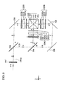
- FIG. 1 is an explanatory diagram showing a projector to which the present invention is applied.
- FIG. 2 is an explanatory diagram showing an enlargement of the illuminating optical system 100 of FIG. 1 .
- FIGS. 3 (A), 3 (B), and 3 (C) are explanatory diagrams showing the polarized light generating optical system 160 .
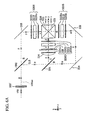
- FIG. 4 is an explanatory diagram showing the main part of the projector 1000 of FIG. 1 .
- FIG. 5 is an explanatory diagram showing the main part of embodiment 2.
- FIG. 6 is an explanatory diagram showing the main part of embodiment 3.
- FIG. 6 (A) is an explanatory diagram showing an alternate aspect of embodiment 3.
- FIG. 7 is an explanatory diagram showing the main part of embodiment 4.
- FIG. 7 (A) is an explanatory diagram showing an alternate aspect of embodiment 4.
- FIGS. 8 and 8 (A) are explanatory diagrams showing the main part of embodiment 5.
- FIGS. 9 and 9 (A) are explanatory diagrams showing the main part of embodiment 6.
- FIG. 10 is an explanatory diagram showing the main part of a conventional projector.
- FIG. 11 is a plan view of the polarizing plate 902 Ri provided on the incident light side of the first liquid crystal light valve 900 R shown in FIG. 10 when viewed from the ⁇ x direction.
- FIG. 1 is an explanatory diagram showing a projector to which the present invention is applied.
- the projector 1000 comprises an illuminating optical system 100 with a light source 120 , a color-separating optical system 200 , a relay optical system 220 , three liquid crystal light valves 300 R, 300 G and 300 B, a cross-dichroic prism 520 and a projection lens 540 .
- Light emitted from the illuminating optical system 100 is separated into colored light of the three colors red (R), green (G) and blue (B) in the color-separating optical system 200 .
- the light of each color is modulated responsive to image information by the liquid crystal light valves 300 R, 300 G and 300 B, respectively.
- the modulated light of each color is combined by the cross-dichroic prism 520 and projected by the projection lens 540 onto the screen SC to display a color image.
- FIG. 2 is an explanatory diagram showing an enlargement of the illuminating optical system 100 of FIG. 1 .
- This illuminating optical system 100 comprises a light source 120 , a first and second lens array 140 and 150 , a polarized light generating optical system 160 and a superimposition lens 170 .
- the light source 120 and the first and second lens arrays 140 and 150 are disposed along the light source optical axis 120 ax as a reference, while the polarized light generating optical system 160 and the superimposition lens 170 are disposed along the system optical axis 100 ax as a reference.
- the light source optical axis 120 ax lies along the central axis of the light beam emitted from the light source 120
- the system optical axis 100 ax lies along the central axis of the light beam emitted from the optical elements in the stage after the polarized light generating optical system 160 .
- the system optical axis 100 ax and the light source optical axis 120 ax are nearly parallel to each other but displaced by a predetermined displacement Dp in the x direction. This displacement Dp will be described later.
- the illuminated area LA illuminated by the illuminating optical system 100 corresponds to the liquid crystal light valves 300 R, 300 G and 300 B of FIG. 1 .
- the light source 120 emits a beam of nearly parallel light.
- the light source 120 comprises a light emitting tube 122 , a reflector 124 with a convex surface in the shape of an ellipsoid of rotation and a parallelizing lens 126 .
- the light emitted from the light emitting tube 122 is reflected by the reflector 124 and the reflected light is converted by the parallelizing lens 126 into light that is nearly parallel to the light source optical axis 120 ax .
- a reflector which has a convex surface in the shape of a paraboloid of rotation may also be used as the light source.
- the first lens array 140 has a plurality of small lenses 142 arranged in a matrix.
- the small lenses 142 are planoconcave lenses whose external shape, when seen from the z direction, is set so that it is similar to that of the illuminated area LA (liquid crystal light valve).
- the first lens array 140 divides the nearly parallel light beam emitted from the light source 120 into a plurality of partial light beams which are emitted.
- the second lens array 150 has a plurality of small lenses 152 arranged in a matrix, like the first lens array 140 .
- the second lens array 150 aligns the central axes of each of the partial light beams emitted from the first lens array 140 so that they are nearly parallel to the system optical axis 100 ax , and forms the images of each of the small lenses 142 of the first lens array 140 upon the illuminated area LA.
- the partial light beams emitted from the small lenses 142 of the first lens array 140 pass through the second lens array 150 to be focused within the polarized light generating optical system 160 .
- the polarized light generating optical system 160 correspond to the polarized light generator in the claimed invention.
- FIGS. 3 (A) and 3 (B) are explanatory diagrams showing the polarized light generating optical system 160 .
- FIG. 3 (A) is a perspective drawing showing the polarized light generating optical system 160
- FIG. 3 (B) is a plan drawing showing a portion of it seen from the +y direction.
- the polarized light generating optical system 160 comprises a shading plate 62 , a polarization beam splitter array 64 and a selective retardation plate 66 .
- the polarization beam splitter array 64 contains a plurality of columnar transmissive members 64 c , each having a section of parallelogram shape, which are adhered together. At the interface between each of the transmissive members 64 c are formed polarized light separating films 64 a and reflecting films 64 b alternately. Note that multi-layer dielectric films are used as the polarized light separation films 64 a while multi-layer dielectric films or metallic films are used as the reflecting films 64 b.
- the shading plate 62 comprises light-blocking surfaces 62 b and open surfaces 62 a disposed in alternating stripes.
- the shading plate 62 blocks the light beams entering the light-blocking surfaces 62 b and transmits the light beams entering the open surfaces 62 a .
- the light-blocking surfaces 62 b and open surfaces 62 a are arranged so that the partial light beams emitted from the first lens array 140 (FIG. 2) enter only at the polarized light separation films 64 a of the polarization beam splitter array 64 and do not enter at the reflecting films 64 b . Specifically, as shown in FIG.
- the centers of the open surfaces 62 a of the shading plate 62 are disposed such that they are roughly aligned with the centers of the polarized light separation films 64 a of the polarization beam splitter array 64 .
- the open width Wp of the open surfaces 62 a in the x direction is set to be roughly equal to the size of the polarized light separation films 64 a in the x direction. At this time, nearly all of the light beams transmitted through the open surfaces 62 a of the shading plate 62 enter only the polarized light separation films 64 a and do not enter the reflecting films 64 b .
- the shading plate 62 can be constructed as a flat plate-shaped transmissive member (for example, a glass plate) with light-blocking film (for example, a chromium film, aluminum film, multi-layer dielectric film, etc.) formed upon portions thereof.
- light-blocking film for example, a chromium film, aluminum film, multi-layer dielectric film, etc.
- each of the partial light beams emitted from the first lens array 140 enters one of the open surfaces 62 a in the shading plate 62 with its main optical axis (central axis) nearly parallel to the system optical axis 100 ax .
- the partial light beams are transmitted through the open surfaces 62 a and incident on the polarized light separation films 64 a .
- the polarized light separation films 64 a separate the partial light beams into s-polarized partial light beams and p-polarized partial light beams.
- the p-polarized partial light beams are transmitted through the polarized light separation films 64 a , while the s-polarized partial light beams are reflected by the polarized light separation films 64 a .
- the s-polarized partial light beams reflected by the polarized light separation films 64 a head toward the reflecting films 64 b and are further reflected by the reflecting films 64 b .
- the p-polarized partial light beams transmitted through the polarized light separation films 64 a and the s-polarized partial light beams reflected by the reflecting films 64 b are nearly parallel to each other.
- the selective retardation plate 66 comprises an open layer 66 a and a ⁇ /2 retardation layer 66 b .
- the open layer 66 a is the portion upon which no ⁇ /2 retardation layer 66 b is formed.
- the open layer 66 a functions to transmit incident linearly polarized light unaltered.
- the ⁇ /2 retardation layer 66 b functions as a polarization conversion element that converts linearly polarized light to another linearly polarized light having a direction of polarization perpendicular to its original direction.
- the p-polarized partial light beams that are transmitted through the polarized light separation films 64 a enter the ⁇ /2 retardation layer 66 b .
- the p-polarized partial light beams are converted to s-polarized partial light beams in the ⁇ /2 retardation layer 66 b and emitted.
- the s-polarized partial light beams reflected by the reflecting films 64 b enter the open layer 66 a so they are emitted unaltered as s-polarized partial light beams.
- non-polarized partial light beams that enter the polarized light generating optical system 160 are converted to s-polarized partial light beams and emitted.
- a ⁇ /2 retardation layer 66 b on only the surfaces where the s-polarized partial light beams reflected by the reflecting films 64 b are emitted, it is possible to convert the partial light beams that enter the polarized light generating optical system 160 into p-polarized partial light beams which are emitted (see FIG. 3 (C)).
- the selective retardation plate 66 it is possible to provide nothing in the open layer 66 a portion and simply affix the ⁇ /2 retardation layer 66 b to the surfaces where the p-polarized partial light beams or s-polarized partial light beams are emitted.
- the centers of the two s-polarized light beams emitted from the polarized light generating optical system 160 are displaced from the center of the incident non-polarized light (s-polarized light+p-polarized light) in the +x direction.
- the amount of this displacement is equal to one-half of the width Wp of the ⁇ /2 retardation layer 66 b (namely the size of the polarized light separation films 64 a in the x direction).
- the light source optical axis 120 ax and the system optical axis 100 ax are displaced by a distance Dp equal to Wp/2.
- the plurality of partial light beams emitted from the first lens array 140 are separated by the polarized light generating optical system 160 into two partial light beams from each partial light beam, and also each is converted nearly completely into one type of linearly polarized light having a predetermined direction of polarization.
- the plurality of partial light beams with the predetermined direction of polarization are superimposed upon the illuminated area LA by means of the superimposition lens 170 shown in FIG. 2 .
- the intensity distribution of the light illuminating the illuminated area LA becomes nearly uniform.
- the illuminating optical system 100 (FIG. 1) emits illuminating light (s-polarized light) with a predetermined direction of polarization, thus illuminating the liquid crystal light valves 300 R, 300 G and 300 B with the aid of the color-separating optical system 200 and relay optical system 220 .
- the color-separating optical system 200 comprises two dichroic mirrors 202 and 204 and a full reflection mirror 208 , separating the light beam emitted from the illuminating optical system 100 into colored light of the three colors red, green and blue.
- the first dichroic mirror 202 transmits the red component of the light emitted from the illuminating optical system 100 but reflects the blue and green components.
- the red light R transmitted by the first dichroic mirror 202 is reflected by the full reflection mirror 208 to head toward the cross-dichroic prism 520 .
- the red light R emitted from the color-separating optical system 200 passes through a field lens 232 and reaches the red light liquid crystal light valve 300 R.
- This field lens 232 converts the various partial light beams emitted from the illuminating optical system 100 into light beams that are parallel to its central axis. Note that the other field lenses 234 and 230 provided on the incident light sides of the other liquid crystal light valves 300 G and 300 B function similarly.
- the green light G is reflected by the second dichroic mirror 204 to head toward the cross-dichroic prism 520 .
- the green light emitted from the color-separating optical system 200 passes through a field lens 234 and reaches the green light liquid crystal light valve 300 G.
- the blue light B transmitted through the second dichroic mirror 204 enters the relay optical system 220 .
- the blue light B that enters the relay optical system 220 passes through an entrance-side lens 222 , relay lens 226 , full reflection mirrors 224 and 228 and an exit-side lens 230 (field lens) to reach the blue light liquid crystal light valve 300 B.
- the reason why the relay optical system 220 is used for the blue light B is so that the length of the optical path for the blue light B is longer than that of the other colors R and G, so by using a relay optical system 220 , the blue light B entering the entrance-side lens 222 can be transmitted to the exit-side lens 230 unaltered.
- the three liquid crystal light valves 300 R, 300 G and 300 B modulate the three colors of light that enter them according to given image information (image signal), thereby generating modulated light beams.
- Each liquid crystal light valve comprises a liquid crystal panel and polarizing plates disposed on its incident side and the exit side. Note that details of the liquid crystal light valves are to be described later.
- the cross-dichroic prism 520 combines the three colors of light (modulated light beams) modulated by the liquid crystal light valves 300 R, 300 G and 300 B to generate composite light which represents a color image.
- the cross-dichroic prism 520 includes a red light-reflecting film 521 and a blue light-reflecting film 522 which are formed in an X shape on the interfaces among four rectangular prisms.
- the red light-reflecting film 521 is formed from a multi-layer dielectric film that reflects red light
- the blue light-reflecting film 522 is formed from a multi-layer dielectric film that reflects blue light. With the red light-reflecting film 521 and blue light-reflecting film 522 , the three colors of light are combined to produce composite light that represents a color image.
- the composite light generated by the cross-dichroic prism 520 is emitted in the direction of the projection lens 540 .
- the projection lens 540 projects the composite light upon the screen SC to display a color image. Note that a telecentric lens can be used as the projection lens 540 .
- FIG. 4 is an explanatory diagram showing the main part of the projector 1000 of FIG. 1 .
- the optical system from the polarized light generating optical system 160 to the cross-dichroic prism 520 in FIG. 1 is drawn with emphasis on the direction of polarization.
- Optical elements that have nearly nothing to do with the direction of polarization are omitted from the drawing.
- embodiment 2 and the other embodiments to be described later are also shown in the same manner.
- the polarized light generating optical system 160 emits s-polarized light.
- s-polarized light is separated by the two dichroic mirrors 202 and 204 into red light R, green light G and blue light B.
- the direction of polarization is unchanged by transmission through the dichroic mirrors 202 and 204 , so the three colors of light remain s-polarized light.
- the s-polarized red light R separated by the first dichroic mirror 202 is reflected by the full reflection mirror 208 and enters the first liquid crystal light valve 300 R.
- the liquid crystal light valve 300 R comprises a liquid crystal panel 301 R and two polarizing plates 302 Ri and 302 Ro provided on its incident side and exit side, respectively.
- a ⁇ /2 retardation plate 303 R is provided on the incident side of the liquid crystal panel 301 R.
- the axes of polarization of the first and second polarizing plates 302 Ri and 302 Ro are set perpendicular to each other, so the first polarizing plate 302 Ri is a p-polarized light transmitting polarizing plate which transmits p-polarized light and the second polarizing plate 302 Ro is an s-polarized light transmitting polarizing plate which transmits s-polarized light.
- the liquid crystal light valve 300 R is provided with a ⁇ /2 retardation plate 303 R and two polarizing plates 302 Ri and 302 Ro like the liquid crystal light valve 900 R shown in FIG. 10 .
- the ⁇ /2 retardation plate 303 R is provided with one surface open to the atmosphere and its other surface in contact with a transmissive glass plate 308 that does not change the direction of polarization.
- the ⁇ /2 retardation plate 303 R is affixed to one surface of the glass plate 308 and polarizing plate 302 Ri is affixed to the other surface.
- the distortion of the ⁇ /2 retardation plate 303 R due to that of the polarizing plate 302 Ri is reduced.
- the polarizing plate 302 Ro on the exit side is provided independently, but it can also be affixed to the exit side of the liquid crystal panel 301 R or to the incident side of the cross-dichroic prism 520 .
- the s-polarized light incident on the first liquid crystal light valve 300 R is converted to p-polarized light by the ⁇ /2 retardation plate 303 R.
- This p-polarized light is transmitted unaltered through the polarizing plate 302 Ri and is modulated by the liquid crystal panel 301 R and thereby, a portion of the light is converted to s-polarized light, and only the s-polarized light is emitted from the polarizing plate 302 Ro.
- the second liquid crystal light valve 300 G comprises a liquid crystal panel 301 G, an s-polarized light transmitting polarizing plate 302 Gi provided on the incident light side of the liquid crystal panel 301 G and a p-polarized light transmitting polarizing plate 302 Go provided on the light exit side.
- the s-polarized green light G entering the second liquid crystal light valve 300 G is transmitted unaltered through the polarizing plate 302 Gi and is modulated by the liquid crystal panel 301 G and thereby, a portion of the light is converted to p-polarized light, and only the p-polarized light is emitted from the polarizing plate 302 Go.
- the s-polarized blue light B separated by the second dichroic mirror 204 is reflected by the full reflection mirrors 224 and 228 and enters the third liquid crystal light valve 300 B.
- the third liquid crystal light valve 300 B comprises a liquid crystal panel 301 B, two polarizing plates 302 Bi and 302 Bo, a ⁇ /2 retardation plate 303 B, and a glass plate 308 to which the ⁇ /2 retardation plate 303 B and polarizing plate 302 Bi are affixed. Note that the third liquid crystal light valve 300 B is similar to the first liquid crystal light valve 300 R, so we shall omit a detailed explanation thereof.
- the cross-dichroic prism 520 includes a red light-reflecting film 521 and a blue light-reflecting film 522 which are formed in an X shape. These reflecting films 521 and 522 normally have excellent reflection characteristics with respect to s-polarized light.
- the light to be reflected by these two reflecting films 521 and 522 is made to be s-polarized light and the light to be transmitted through the two reflecting films 521 and 522 is made to be p-polarized light.
- the s-polarized red light modulated by the first liquid crystal light valve 300 R is reflected by the red light-reflecting film 521
- nearly all of the p-polarized red light modulated by the third liquid crystal light valve 300 B is reflected by the blue light-reflecting film 522 .
- nearly all of the p-polarized green light modulated by the second liquid crystal light valve 300 G is transmitted by the red light-reflecting film 521 and blue light-reflecting film 522 .
- the cross-dichroic prism 520 can efficiently combine the various beams of polarized light emitted from the three liquid crystal light valves 300 R, 300 G and 300 B. Note that in FIG. 4, for simplicity in drawing the positions at which the green light and blue light are reflected are drawn at positions shifted from the two reflecting films 521 and 522 .
- the ⁇ /2 retardation plates 303 R and 303 B are provided with one surface open to the atmosphere and their other surface in contact with a transmissive glass plate 308 that does not change the direction of polarization. Accordingly, even if the polarizing plates 302 Ri and 302 Bi are distorted by heat, the ⁇ /2 retardation plates 303 R and 303 B will not distorted so much.
- the ⁇ /2 retardation plates 303 R and 303 B are able to convert the incident s-polarized light readily into p-polarized light, so the intensity of the p-polarized light emitted from the polarizing plates 302 Ri and 302 Bi on the incident light side and the intensity of the s-polarized light emitted from the polarizing plates 302 Ro and 302 Bo on the light exit side is not reduced compared to that of the conventional projector of FIG. 10 .
- the first through third liquid crystal light valves 300 R, 300 G and 300 B in this embodiment correspond to the first through third electro-optical devices of the claimed invention except for the ⁇ /2 retardation plates 303 R and 303 B.
- the projector of this embodiment has the first through third electro-optical devices of the claimed invention, and additionally ⁇ /2 retardation plates on the incident light sides.
- electro-optical device is typically used in the narrow sense of an electro-optical device meaning the liquid crystal panel alone, but in this Specification, it refers to an electro-optical device in the broad sense of including the liquid crystal panel and polarizing plates.
- the s-polarized light emitted from the first and third liquid crystal light valves 300 R and 300 B correspond to the first and third beams of modulated light having a first direction of polarization in the claimed invention
- the p-polarized light emitted from the second liquid crystal light valve 300 G corresponds to the second beam of modulated light having a second direction of polarization in the claimed invention.
- FIG. 5 is an explanatory diagram showing the main part of embodiment 2.
- the ⁇ /2 retardation plates 303 R and 303 B are provided on the incident light side of the liquid crystal light valves 300 R and 300 B, but in embodiment 2, the ⁇ /2 retardation plates 313 R and 313 B are provided on the light exit side of the liquid crystal light valves 310 R and 310 B.
- s-polarized light transmitting polarizing plates 312 Ri and 312 Bi are provided on the incident light side while p-polarized light transmitting polarizing plates 312 Ro and 312 Bo are provided on the light exit side.
- the first liquid crystal light valve 310 R s-polarized red light is transmitted through the polarizing plate 312 Ri unaltered and enters liquid crystal panel 311 R.
- the liquid crystal panel 311 R converts a portion of the incident s-polarized light into p-polarized light and only the p-polarized light is emitted from the p-polarized light transmitting polarizing plate 312 Ro disposed on the light exit side.
- the p-polarized light emitted from the polarizing plate 312 Ro passes through the glass plate 318 , enters the ⁇ /2 retardation plate 313 R, is converted to s-polarized light and emitted.
- the other constituent elements are identical to those of embodiment 1, so we shall omit a detailed explanation thereof.
- the ⁇ /2 retardation plates 313 R and 313 B are provided with one surface open to the atmosphere and their other surface in contact with a transmissive glass plate 318 that does not change the direction of polarization. Therefore, the distortion of the ⁇ /2 retardation plates 313 R and 313 B due to that of the polarizing plates 312 Ri and 312 Bi can be reduced. As a result, the chrominance nonuniformities will be reduced in the displayed color image.
- the projector in this embodiment correspond to the first and third electro-optical devices of the claimed invention with ⁇ /2 retardation plates provided on the light exit side.
- FIG. 6 is an explanatory diagram showing the main part of embodiment 3.
- Embodiment 3 has the structure where the polarized light generating optical system 160 of embodiment 1 (FIG. 4) is replaced with a polarized light generating optical system 160 ′ that emits p-polarized light.
- the ⁇ /2 retardation plates 303 R and 303 B are provided on the incident light side of the liquid crystal light valves 300 R and 300 B, but in embodiment 3 , a ⁇ /2 retardation plate 323 G is provided only on the incident light side of the liquid crystal light valve 320 G.
- the other constituent elements are identical to those of embodiment 1.
- p-polarized light transmitting polarizing plates 322 Ri and 322 Bi are provided on the incident light sides of the first and third liquid crystal light valves 320 R and 320 B and s-polarized light transmitting polarizing plates 322 Ro and 322 Bo are provided on their light exit sides.
- an s-polarized light transmitting polarizing plate 322 Gi is provided on the incident light side of the second liquid crystal light valve 320 G and a p-polarized light transmitting polarizing plate 322 Go is provided on its light exit side.
- the ⁇ /2 retardation plate 323 G is provided with one surface open to the atmosphere and its other surface in contact with a transmissive glass plate 328 that does not change the direction of polarization. Therefore, the distortion of the ⁇ /2 retardation plate 323 G due to that of the polarizing plate 322 Gi can be reduced. As a result, the chrominance nonuniformities will be reduced in the displayed color image.
- the projector in this embodiment corresponds to the second electro-optical device of the claimed invention with a ⁇ /2 retardation plate provided on the incident light side.
- FIG. 7 is an explanatory diagram showing the main part of embodiment 4.
- the ⁇ /2 retardation plate 323 G is provided on the incident light side of the liquid crystal light valve 320 G, but in embodiment 4, a ⁇ /2 retardation plate 333 G is provided on the light exit side of the liquid crystal light valve 330 G.
- the second liquid crystal light valve 330 G in embodiment 4 has a p-polarized light transmitting polarizing plate 332 Gi provided on the incident light side and an s-polarized light transmitting polarizing plate 332 Go provided on the light exit side.
- the ⁇ /2 retardation plate 333 G is provided with one surface open to the atmosphere and its other surface in contact with a transmissive glass plate 338 that does not change the direction of polarization. Therefore, the distortion of the ⁇ /2 retardation plate 333 G due to that of the polarizing plate 332 Go can be reduced. As a result, it is possible to reduce the chrominance nonuniformities in the displayed color image.
- the projector in this embodiment corresponds to the second electro-optical device of the claimed invention with a ⁇ /2 retardation plate provided on the light exit side.
- FIG. 8 is an explanatory diagram showing the main part of embodiment 5. Note that in FIG. 8, the three field lenses 232 , 234 and 230 ′ as shown in the projector 1000 of FIG. 1 are also shown.
- the ⁇ /2 retardation plates 303 R and 303 B on the incident light side of the first and third liquid crystal light valves 300 R and 300 B are each affixed upon a glass plate 308 , but in embodiment 5, they are affixed to the light exit side of field lenses 232 and 230 ′ provided on the incident light sides of the first and third liquid crystal light valves 300 Ra and 300 Ba.
- a planoconvex field lens 230 ′ is used instead of the double-convex field lens 230 of FIG. 1 . If the ⁇ /2 retardation plates 303 R and 303 B are affixed to the field lenses 232 and 230 ′ in this manner, it is possible to omit the glass plate 308 used in embodiment 1 (FIG. 4 ).
- the two ⁇ /2 retardation plates 303 R and 303 G are provided with one surface open to the atmosphere and their other surface in contact with the field lenses 232 and 230 ′ that do not change the direction of polarization. Therefore, in the same manner as in embodiment 1, it is possible to reduce the chrominance nonuniformities in the displayed color image. Note that this is similarly applicable to the projector of embodiment 3 shown in FIG. 6, and in this case, it is sufficient that the ⁇ /2 retardation plate 323 G of the liquid crystal light valve 320 G be affixed to the field lens 234 .
- the projector in this embodiment corresponds to the first and third electro-optical devices of the claimed invention with ⁇ /2 retardation plates provided on the incident light side.
- FIG. 9 is an explanatory diagram showing the main part of embodiment 6.
- the ⁇ /2 retardation plates 313 R and 313 B on the light exit sides of the first and third liquid crystal light valves 310 R and 310 B are each affixed upon a glass plate 318 , but in embodiment 6, they are affixed to the two incident light sides of the cross-dichroic prism 520 provided on the light exit sides of the first and third liquid crystal light valves 310 Ra and 310 Ba.
- the two ⁇ /2 retardation plates 313 R and 313 G are provided with one surface open to the atmosphere and their other surface in contact with the cross-dichroic prism 520 that does not change the direction of polarization. Therefore, in the same manner as in embodiment 2, it is possible to reduce the chrominance nonuniformities in the displayed color image. Note that this is similarly applicable to the projector of embodiment 4 shown in FIG. 7, and in this case, it is sufficient that the ⁇ /2 retardation plate 333 G of the second liquid crystal light valve 330 G be affixed to the cross-dichroic prism 520 .
- the projector in this embodiment corresponds to the first and third electro-optical devices of the claimed invention with ⁇ /2 retardation plates provided on the light exit side.
- the ⁇ /2 retardation plate is provided with one surface open to the atmosphere and its other surface in contact with a transmissive member that does not change the direction of polarization.
- the ⁇ /2 retardation plate is provided together with a polarizing plate affixed to a glass plate, a cross-dichroic prism, field lens or other optical element, but the ⁇ /2 retardation plate can also be provided independently.
- a ⁇ /2 retardation plate simply affixed to a glass plate can be provided independently.
- the ⁇ /2 retardation plate is provided with one surface open to the atmosphere and its other surface in contact with a transmissive member that does not change the direction of polarization, so it is possible to reduce chrominance nonuniformities in the images displayed.
- a polarizing plate contained in a liquid crystal light valve may be affixed to a transmissive member to which a ⁇ /2 retardation plate is affixed, as shown in FIGS. 4-7, or that may be affixed to another transmissive member different from the transmissive member to which the ⁇ /2 retardation plate is affixed, as shown in FIGS. 8 (A), 9 (A), 6 (A) and 7 (A) (e.g., transmissive elements 308 , 318 , 328 , and 338 , respectively).
- the distortion of the ⁇ /2 retardation plate can be reduced, so it is possible to reduce chrominance nonuniformities in the images displayed.
- the green beam of modulated light emitted from the second liquid crystal light valve is always made to be p-polarized light
- the red and blue beams of modulated light emitted from the first and third liquid crystal light valves are always made to be s-polarized light, but the colors of the light made to be p-polarized light or s-polarized light are not limited to these.
- the colors of the light made to be p-polarized light or s-polarized light are not limited to these.
- an illuminating optical system 100 that emits s-polarized light or p-polarized light is used, but in the case wherein polarizing plates are provided on the incident light sides of the liquid crystal light valves, the incident light may also be non-polarized light. By doing so, it is possible to omit the polarized light generating optical systems 160 and 160 ′ provided on the illuminating optical system. In this case, it is sufficient to provide the ⁇ /2 retardation plates on the light exit sides of the liquid crystal light valves.
- the light incident on the polarizing plates on the incident light side can be utilized effectively, so it has the advantage that a bright image can be displayed on the screen SC.
- the polarizing plates provided on the incident light sides of the liquid crystal light valves may be omitted.
- the polarizing plates provided on the incident light sides of the liquid crystal light valves are used to increase the degree of polarization of the illuminating light, they may be omitted if the degree of polarization of the light incident on the liquid crystal light valves is sufficiently high. In this case, it is sufficient to provide the ⁇ /2 retardation plates and polarizing plates on the light exit sides of the liquid crystal light valves.
- ⁇ /2 retardation plates are provided on the incident light sides or light exit sides of the liquid crystal light valves, but it is also possible to combine two ⁇ /4 retardation plates to achieve the function of a single ⁇ /2 retardation plate.
- a first ⁇ /4 retardation plate instead of the ⁇ /2 retardation plate 303 R for the first liquid crystal light valve 300 R, and also provided a second ⁇ /4 retardation plate on the light exit side of the field lens 232 (FIG. 1 ).
- the ⁇ /4 retardation plate it is preferable for the ⁇ /4 retardation plate to be provided with one surface open to the atmosphere and its other surface in contact with a transmissive member that does not change the direction of polarization.
- a cross-dichroic prism 520 is used as the color combiner of the present invention, but this is not a limitation.
- the color combiner it is possible to use the two light-reflecting films 521 and 522 contained in the cross-dichroic prism 520 but formed upon glass plates, for example.
- the color combiner it is sufficient to use something that reflects the incident first and third beams of modulated light but transmits the second beam of modulated light, thereby combining the first through third beams of modulated light.
Landscapes
- Engineering & Computer Science (AREA)
- Multimedia (AREA)
- Signal Processing (AREA)
- Physics & Mathematics (AREA)
- General Physics & Mathematics (AREA)
- Projection Apparatus (AREA)
- Liquid Crystal (AREA)
- Devices For Indicating Variable Information By Combining Individual Elements (AREA)
- Luminescent Compositions (AREA)
- Developing Agents For Electrophotography (AREA)
- Organic Low-Molecular-Weight Compounds And Preparation Thereof (AREA)
- Transforming Electric Information Into Light Information (AREA)
- Video Image Reproduction Devices For Color Tv Systems (AREA)
Applications Claiming Priority (4)
| Application Number | Priority Date | Filing Date | Title |
|---|---|---|---|
| JP20954999 | 1999-07-23 | ||
| JP11-209549 | 1999-07-23 | ||
| JP2000127549A JP2001100311A (ja) | 1999-07-23 | 2000-04-27 | プロジェクタ |
| JP2000-127549 | 2000-04-27 |
Publications (1)
| Publication Number | Publication Date |
|---|---|
| US6646690B1 true US6646690B1 (en) | 2003-11-11 |
Family
ID=26517525
Family Applications (1)
| Application Number | Title | Priority Date | Filing Date |
|---|---|---|---|
| US09/619,573 Expired - Lifetime US6646690B1 (en) | 1999-07-23 | 2000-07-19 | Arrangement of λ/2 retardation plate in projector |
Country Status (8)
| Country | Link |
|---|---|
| US (1) | US6646690B1 (enExample) |
| EP (2) | EP1071292B1 (enExample) |
| JP (1) | JP2001100311A (enExample) |
| KR (1) | KR100383509B1 (enExample) |
| CN (1) | CN1171111C (enExample) |
| AT (1) | ATE373390T1 (enExample) |
| DE (1) | DE60036339T2 (enExample) |
| TW (1) | TW500966B (enExample) |
Cited By (9)
| Publication number | Priority date | Publication date | Assignee | Title |
|---|---|---|---|---|
| US20030072012A1 (en) * | 2001-10-16 | 2003-04-17 | Seiko Epson Corporation | Producing method of optical device, positioning master, optical device and projector |
| US20050012870A1 (en) * | 2003-07-18 | 2005-01-20 | Hitachi, Ltd. | Projection type display device and back projection type display device using the same |
| US20050140926A1 (en) * | 2003-12-26 | 2005-06-30 | Koji Hirata | Projection type image display device, rear projection type image display device, optical unit, and screen unit |
| US20050248845A1 (en) * | 2002-08-30 | 2005-11-10 | Seo Eun S | Polarization conversion system |
| US20080055550A1 (en) * | 2006-09-04 | 2008-03-06 | Samsung Techwin Co., Ltd. | Microprojector |
| US20130271945A1 (en) | 2004-02-06 | 2013-10-17 | Nikon Corporation | Polarization-modulating element, illumination optical apparatus, exposure apparatus, and exposure method |
| US8675177B2 (en) | 2003-04-09 | 2014-03-18 | Nikon Corporation | Exposure method and apparatus, and method for fabricating device with light amount distribution having light larger in first and second pairs of areas |
| US9140992B2 (en) | 2003-10-28 | 2015-09-22 | Nikon Corporation | Illumination optical apparatus and projection exposure apparatus |
| US9164209B2 (en) | 2003-11-20 | 2015-10-20 | Nikon Corporation | Illumination optical apparatus, exposure apparatus, and exposure method with optical member with optical rotatory power having different thicknesses to rotate linear polarization direction |
Families Citing this family (6)
| Publication number | Priority date | Publication date | Assignee | Title |
|---|---|---|---|---|
| JP4109901B2 (ja) * | 2001-05-29 | 2008-07-02 | キヤノン株式会社 | 画像表示装置 |
| DE60217342T2 (de) * | 2001-06-08 | 2007-08-16 | Sony Corp. | Zündeinrichtung für eine entladungslampe und projektoreinrichtung |
| TW200503554A (en) * | 2003-05-01 | 2005-01-16 | Koninkl Philips Electronics Nv | Projector system |
| JP4141938B2 (ja) * | 2003-11-10 | 2008-08-27 | セイコーエプソン株式会社 | プロジェクタ |
| TWI423301B (zh) * | 2005-01-21 | 2014-01-11 | 尼康股份有限公司 | 照明光學裝置、曝光裝置、曝光方法以及元件製造方法 |
| JP4586743B2 (ja) | 2006-02-20 | 2010-11-24 | セイコーエプソン株式会社 | プロジェクタ |
Citations (6)
| Publication number | Priority date | Publication date | Assignee | Title |
|---|---|---|---|---|
| US5490006A (en) * | 1993-04-22 | 1996-02-06 | Matsushita Electric Industrial Co., Ltd. | Liquid crystal light valve apparatus with a pair of non-parallel phase difference plates |
| US5738426A (en) * | 1995-12-08 | 1998-04-14 | Mitsubishi Denki Kabushiki Kaisha | Projection type display apparatus and multi-vision projection type display apparatus |
| JPH10186548A (ja) | 1996-10-30 | 1998-07-14 | Seiko Epson Corp | 投写型表示装置 |
| CN1206120A (zh) | 1997-04-10 | 1999-01-27 | 松下电器产业株式会社 | 投写式图像显示装置 |
| US6176583B1 (en) * | 1998-06-22 | 2001-01-23 | Minolta Co., Ltd. | Polarization conversion dichroic mirror and a liquid crystal projector |
| US6224217B1 (en) * | 1998-09-28 | 2001-05-01 | Matsushita Electric Industrial Co., Ltd. | Optical illumination apparatus and image projection apparatus |
Family Cites Families (5)
| Publication number | Priority date | Publication date | Assignee | Title |
|---|---|---|---|---|
| JP2589407B2 (ja) * | 1990-09-28 | 1997-03-12 | シャープ株式会社 | 投影型画像表示装置 |
| JP3039570B2 (ja) * | 1991-06-24 | 2000-05-08 | キヤノン株式会社 | 投写表示装置 |
| JP3074831B2 (ja) * | 1991-09-10 | 2000-08-07 | 株式会社日立製作所 | 液晶プロジェクション装置 |
| US5541673A (en) * | 1993-09-03 | 1996-07-30 | Nec Corporation | Projector having a halfwave plate disposed in light-leaving side of a light valve |
| JPH10186547A (ja) * | 1996-10-30 | 1998-07-14 | Seiko Epson Corp | 投写型表示装置 |
-
2000
- 2000-04-27 JP JP2000127549A patent/JP2001100311A/ja not_active Withdrawn
- 2000-07-19 KR KR10-2000-0041259A patent/KR100383509B1/ko not_active Expired - Fee Related
- 2000-07-19 US US09/619,573 patent/US6646690B1/en not_active Expired - Lifetime
- 2000-07-19 TW TW089114426A patent/TW500966B/zh active
- 2000-07-21 EP EP00306230A patent/EP1071292B1/en not_active Expired - Lifetime
- 2000-07-21 AT AT00306230T patent/ATE373390T1/de not_active IP Right Cessation
- 2000-07-21 EP EP04018448A patent/EP1519590A1/en not_active Withdrawn
- 2000-07-21 DE DE60036339T patent/DE60036339T2/de not_active Expired - Lifetime
- 2000-07-24 CN CNB001217437A patent/CN1171111C/zh not_active Expired - Fee Related
Patent Citations (7)
| Publication number | Priority date | Publication date | Assignee | Title |
|---|---|---|---|---|
| US5490006A (en) * | 1993-04-22 | 1996-02-06 | Matsushita Electric Industrial Co., Ltd. | Liquid crystal light valve apparatus with a pair of non-parallel phase difference plates |
| US5738426A (en) * | 1995-12-08 | 1998-04-14 | Mitsubishi Denki Kabushiki Kaisha | Projection type display apparatus and multi-vision projection type display apparatus |
| JPH10186548A (ja) | 1996-10-30 | 1998-07-14 | Seiko Epson Corp | 投写型表示装置 |
| CN1206120A (zh) | 1997-04-10 | 1999-01-27 | 松下电器产业株式会社 | 投写式图像显示装置 |
| US6042236A (en) * | 1997-04-10 | 2000-03-28 | Matsushita Electric Industrial Co., Ltd. | Projection type video image display device |
| US6176583B1 (en) * | 1998-06-22 | 2001-01-23 | Minolta Co., Ltd. | Polarization conversion dichroic mirror and a liquid crystal projector |
| US6224217B1 (en) * | 1998-09-28 | 2001-05-01 | Matsushita Electric Industrial Co., Ltd. | Optical illumination apparatus and image projection apparatus |
Cited By (30)
| Publication number | Priority date | Publication date | Assignee | Title |
|---|---|---|---|---|
| US20030072012A1 (en) * | 2001-10-16 | 2003-04-17 | Seiko Epson Corporation | Producing method of optical device, positioning master, optical device and projector |
| US20050248845A1 (en) * | 2002-08-30 | 2005-11-10 | Seo Eun S | Polarization conversion system |
| US7002743B2 (en) * | 2002-08-30 | 2006-02-21 | Lg Electronics Inc. | Polarization conversion system |
| US9146474B2 (en) | 2003-04-09 | 2015-09-29 | Nikon Corporation | Exposure method and apparatus, and method for fabricating device with light amount distribution having light larger and different linear polarization states in an on-axis area and a plurality of off-axis areas |
| US9885959B2 (en) | 2003-04-09 | 2018-02-06 | Nikon Corporation | Illumination optical apparatus having deflecting member, lens, polarization member to set polarization in circumference direction, and optical integrator |
| US9678437B2 (en) | 2003-04-09 | 2017-06-13 | Nikon Corporation | Illumination optical apparatus having distribution changing member to change light amount and polarization member to set polarization in circumference direction |
| US9164393B2 (en) | 2003-04-09 | 2015-10-20 | Nikon Corporation | Exposure method and apparatus, and method for fabricating device with light amount distribution having light larger in four areas |
| US8675177B2 (en) | 2003-04-09 | 2014-03-18 | Nikon Corporation | Exposure method and apparatus, and method for fabricating device with light amount distribution having light larger in first and second pairs of areas |
| US20050012870A1 (en) * | 2003-07-18 | 2005-01-20 | Hitachi, Ltd. | Projection type display device and back projection type display device using the same |
| US7499111B2 (en) | 2003-07-18 | 2009-03-03 | Hitachi, Ltd. | Projection type display device and back projection type display device using the same |
| US9146476B2 (en) | 2003-10-28 | 2015-09-29 | Nikon Corporation | Illumination optical apparatus and projection exposure apparatus |
| US9760014B2 (en) | 2003-10-28 | 2017-09-12 | Nikon Corporation | Illumination optical apparatus and projection exposure apparatus |
| US9140993B2 (en) | 2003-10-28 | 2015-09-22 | Nikon Corporation | Illumination optical apparatus and projection exposure apparatus |
| US9140992B2 (en) | 2003-10-28 | 2015-09-22 | Nikon Corporation | Illumination optical apparatus and projection exposure apparatus |
| US9423697B2 (en) | 2003-10-28 | 2016-08-23 | Nikon Corporation | Illumination optical apparatus and projection exposure apparatus |
| US9423698B2 (en) | 2003-10-28 | 2016-08-23 | Nikon Corporation | Illumination optical apparatus and projection exposure apparatus |
| US9244359B2 (en) | 2003-10-28 | 2016-01-26 | Nikon Corporation | Illumination optical apparatus and projection exposure apparatus |
| US10281632B2 (en) | 2003-11-20 | 2019-05-07 | Nikon Corporation | Illumination optical apparatus, exposure apparatus, and exposure method with optical member with optical rotatory power to rotate linear polarization direction |
| US9885872B2 (en) | 2003-11-20 | 2018-02-06 | Nikon Corporation | Illumination optical apparatus, exposure apparatus, and exposure method with optical integrator and polarization member that changes polarization state of light |
| US9164209B2 (en) | 2003-11-20 | 2015-10-20 | Nikon Corporation | Illumination optical apparatus, exposure apparatus, and exposure method with optical member with optical rotatory power having different thicknesses to rotate linear polarization direction |
| US7237901B2 (en) | 2003-12-26 | 2007-07-03 | Hitachi, Ltd. | Projection type image display device, rear projection type image display device, optical unit, and screen unit |
| US20050140926A1 (en) * | 2003-12-26 | 2005-06-30 | Koji Hirata | Projection type image display device, rear projection type image display device, optical unit, and screen unit |
| US9140990B2 (en) | 2004-02-06 | 2015-09-22 | Nikon Corporation | Polarization-modulating element, illumination optical apparatus, exposure apparatus, and exposure method |
| US9429848B2 (en) | 2004-02-06 | 2016-08-30 | Nikon Corporation | Polarization-modulating element, illumination optical apparatus, exposure apparatus, and exposure method |
| US20130271945A1 (en) | 2004-02-06 | 2013-10-17 | Nikon Corporation | Polarization-modulating element, illumination optical apparatus, exposure apparatus, and exposure method |
| US10007194B2 (en) | 2004-02-06 | 2018-06-26 | Nikon Corporation | Polarization-modulating element, illumination optical apparatus, exposure apparatus, and exposure method |
| US10234770B2 (en) | 2004-02-06 | 2019-03-19 | Nikon Corporation | Polarization-modulating element, illumination optical apparatus, exposure apparatus, and exposure method |
| US10241417B2 (en) | 2004-02-06 | 2019-03-26 | Nikon Corporation | Polarization-modulating element, illumination optical apparatus, exposure apparatus, and exposure method |
| US9423694B2 (en) | 2004-02-06 | 2016-08-23 | Nikon Corporation | Polarization-modulating element, illumination optical apparatus, exposure apparatus, and exposure method |
| US20080055550A1 (en) * | 2006-09-04 | 2008-03-06 | Samsung Techwin Co., Ltd. | Microprojector |
Also Published As
| Publication number | Publication date |
|---|---|
| DE60036339D1 (de) | 2007-10-25 |
| KR20010021101A (ko) | 2001-03-15 |
| CN1171111C (zh) | 2004-10-13 |
| CN1281995A (zh) | 2001-01-31 |
| TW500966B (en) | 2002-09-01 |
| EP1519590A1 (en) | 2005-03-30 |
| DE60036339T2 (de) | 2008-06-05 |
| JP2001100311A (ja) | 2001-04-13 |
| EP1071292A3 (en) | 2004-03-10 |
| KR100383509B1 (ko) | 2003-05-12 |
| EP1071292B1 (en) | 2007-09-12 |
| EP1071292A2 (en) | 2001-01-24 |
| ATE373390T1 (de) | 2007-09-15 |
Similar Documents
| Publication | Publication Date | Title |
|---|---|---|
| USRE39243E1 (en) | Optical element, polarization illumination device, and projector | |
| US7364302B2 (en) | Projection display system using multiple light sources and polarizing element for using with same | |
| US20070121310A1 (en) | Lighting system and projector | |
| JPH11271677A (ja) | カラー投影表示装置 | |
| US6646690B1 (en) | Arrangement of λ/2 retardation plate in projector | |
| JPH03103840A (ja) | 投射装置 | |
| JP2006145644A (ja) | 偏光分離装置及びそれを用いた投射型表示装置 | |
| KR20090032990A (ko) | 투사형 액정 표시 장치 및 보상판 | |
| US6144492A (en) | Optical block and display unit | |
| US6805444B2 (en) | Projector comprising an optical component having a rock crystal member | |
| US6607276B1 (en) | Illuminating optical system and projector | |
| US6665122B1 (en) | Projection-type image display apparatus | |
| US6987618B2 (en) | Polarization converting device, illumination optical system and projector | |
| US10088743B2 (en) | Polarization conversion element and projector | |
| JP2004233961A (ja) | 投射型表示装置 | |
| US7374291B2 (en) | Projection optical system and image display apparatus using same | |
| US7359122B2 (en) | Prism assembly | |
| US20240192579A1 (en) | Wavelength selective phase difference element and projection display apparatus | |
| US6365526B1 (en) | Optical illumination system and projection apparatus | |
| US6612702B1 (en) | Projection display device | |
| JP3449068B2 (ja) | プロジェクタ装置 | |
| US7988298B2 (en) | Projector having a shifted or rotated optical axis | |
| US20240329514A1 (en) | Projector | |
| JP4019557B2 (ja) | 投射型表示装置 | |
| JP5104338B2 (ja) | プロジェクタ |
Legal Events
| Date | Code | Title | Description |
|---|---|---|---|
| AS | Assignment |
Owner name: SEIKO EPSON CORPORATION, JAPAN Free format text: ASSIGNMENT OF ASSIGNORS INTEREST;ASSIGNOR:TAKEZAWA, TAKESHI;REEL/FRAME:011273/0469 Effective date: 20001013 |
|
| STCF | Information on status: patent grant |
Free format text: PATENTED CASE |
|
| FEPP | Fee payment procedure |
Free format text: PAYER NUMBER DE-ASSIGNED (ORIGINAL EVENT CODE: RMPN); ENTITY STATUS OF PATENT OWNER: LARGE ENTITY Free format text: PAYOR NUMBER ASSIGNED (ORIGINAL EVENT CODE: ASPN); ENTITY STATUS OF PATENT OWNER: LARGE ENTITY |
|
| FPAY | Fee payment |
Year of fee payment: 4 |
|
| FPAY | Fee payment |
Year of fee payment: 8 |
|
| FPAY | Fee payment |
Year of fee payment: 12 |