US6302515B2 - Transaction printing device having wiper debris collectors - Google Patents
Transaction printing device having wiper debris collectors Download PDFInfo
- Publication number
- US6302515B2 US6302515B2 US09/472,716 US47271699A US6302515B2 US 6302515 B2 US6302515 B2 US 6302515B2 US 47271699 A US47271699 A US 47271699A US 6302515 B2 US6302515 B2 US 6302515B2
- Authority
- US
- United States
- Prior art keywords
- wiper
- debris
- printhead
- printing device
- cartridge
- Prior art date
- Legal status (The legal status is an assumption and is not a legal conclusion. Google has not performed a legal analysis and makes no representation as to the accuracy of the status listed.)
- Expired - Fee Related
Links
- 238000007639 printing Methods 0.000 title claims abstract description 29
- 238000004140 cleaning Methods 0.000 claims abstract description 46
- 238000009825 accumulation Methods 0.000 claims abstract description 9
- 239000012530 fluid Substances 0.000 claims description 10
- 238000013519 translation Methods 0.000 claims description 3
- 238000004891 communication Methods 0.000 claims description 2
- 239000000758 substrate Substances 0.000 description 26
- 239000010409 thin film Substances 0.000 description 24
- 238000004519 manufacturing process Methods 0.000 description 14
- 239000011521 glass Substances 0.000 description 11
- 244000309464 bull Species 0.000 description 8
- 238000007641 inkjet printing Methods 0.000 description 7
- 230000009471 action Effects 0.000 description 6
- 239000004020 conductor Substances 0.000 description 6
- 238000000034 method Methods 0.000 description 6
- DGAQECJNVWCQMB-PUAWFVPOSA-M Ilexoside XXIX Chemical compound C[C@@H]1CC[C@@]2(CC[C@@]3(C(=CC[C@H]4[C@]3(CC[C@@H]5[C@@]4(CC[C@@H](C5(C)C)OS(=O)(=O)[O-])C)C)[C@@H]2[C@]1(C)O)C)C(=O)O[C@H]6[C@@H]([C@H]([C@@H]([C@H](O6)CO)O)O)O.[Na+] DGAQECJNVWCQMB-PUAWFVPOSA-M 0.000 description 5
- 238000005530 etching Methods 0.000 description 5
- 238000007790 scraping Methods 0.000 description 5
- 229910052708 sodium Inorganic materials 0.000 description 5
- 239000011734 sodium Substances 0.000 description 5
- 239000012212 insulator Substances 0.000 description 4
- 230000004888 barrier function Effects 0.000 description 3
- 238000009792 diffusion process Methods 0.000 description 3
- 230000005484 gravity Effects 0.000 description 3
- 238000000059 patterning Methods 0.000 description 3
- 235000008733 Citrus aurantifolia Nutrition 0.000 description 2
- KDLHZDBZIXYQEI-UHFFFAOYSA-N Palladium Chemical compound [Pd] KDLHZDBZIXYQEI-UHFFFAOYSA-N 0.000 description 2
- CDBYLPFSWZWCQE-UHFFFAOYSA-L Sodium Carbonate Chemical compound [Na+].[Na+].[O-]C([O-])=O CDBYLPFSWZWCQE-UHFFFAOYSA-L 0.000 description 2
- 235000011941 Tilia x europaea Nutrition 0.000 description 2
- 229910045601 alloy Inorganic materials 0.000 description 2
- 239000000956 alloy Substances 0.000 description 2
- 229910052782 aluminium Inorganic materials 0.000 description 2
- XAGFODPZIPBFFR-UHFFFAOYSA-N aluminium Chemical compound [Al] XAGFODPZIPBFFR-UHFFFAOYSA-N 0.000 description 2
- 230000015572 biosynthetic process Effects 0.000 description 2
- 238000009434 installation Methods 0.000 description 2
- 239000004571 lime Substances 0.000 description 2
- 229910052751 metal Inorganic materials 0.000 description 2
- 239000002184 metal Substances 0.000 description 2
- 150000002739 metals Chemical class 0.000 description 2
- 238000002161 passivation Methods 0.000 description 2
- BASFCYQUMIYNBI-UHFFFAOYSA-N platinum Chemical compound [Pt] BASFCYQUMIYNBI-UHFFFAOYSA-N 0.000 description 2
- VYZAMTAEIAYCRO-UHFFFAOYSA-N Chromium Chemical compound [Cr] VYZAMTAEIAYCRO-UHFFFAOYSA-N 0.000 description 1
- 229910052581 Si3N4 Inorganic materials 0.000 description 1
- VYPSYNLAJGMNEJ-UHFFFAOYSA-N Silicium dioxide Chemical compound O=[Si]=O VYPSYNLAJGMNEJ-UHFFFAOYSA-N 0.000 description 1
- 239000000853 adhesive Substances 0.000 description 1
- 230000001070 adhesive effect Effects 0.000 description 1
- 238000011109 contamination Methods 0.000 description 1
- 230000008021 deposition Effects 0.000 description 1
- 238000005137 deposition process Methods 0.000 description 1
- 238000001035 drying Methods 0.000 description 1
- 238000005516 engineering process Methods 0.000 description 1
- 238000010304 firing Methods 0.000 description 1
- PCHJSUWPFVWCPO-UHFFFAOYSA-N gold Chemical compound [Au] PCHJSUWPFVWCPO-UHFFFAOYSA-N 0.000 description 1
- 239000010931 gold Substances 0.000 description 1
- 229910052737 gold Inorganic materials 0.000 description 1
- 239000011796 hollow space material Substances 0.000 description 1
- 230000002452 interceptive effect Effects 0.000 description 1
- 230000003902 lesion Effects 0.000 description 1
- 239000000463 material Substances 0.000 description 1
- 230000005012 migration Effects 0.000 description 1
- 238000013508 migration Methods 0.000 description 1
- 238000012986 modification Methods 0.000 description 1
- 230000004048 modification Effects 0.000 description 1
- 239000012811 non-conductive material Substances 0.000 description 1
- 229910052763 palladium Inorganic materials 0.000 description 1
- 239000000049 pigment Substances 0.000 description 1
- 229910052697 platinum Inorganic materials 0.000 description 1
- 230000008569 process Effects 0.000 description 1
- 239000004065 semiconductor Substances 0.000 description 1
- 229910052710 silicon Inorganic materials 0.000 description 1
- 239000010703 silicon Substances 0.000 description 1
- HBMJWWWQQXIZIP-UHFFFAOYSA-N silicon carbide Chemical compound [Si+]#[C-] HBMJWWWQQXIZIP-UHFFFAOYSA-N 0.000 description 1
- 229910010271 silicon carbide Inorganic materials 0.000 description 1
- HQVNEWCFYHHQES-UHFFFAOYSA-N silicon nitride Chemical compound N12[Si]34N5[Si]62N3[Si]51N64 HQVNEWCFYHHQES-UHFFFAOYSA-N 0.000 description 1
- 229910052814 silicon oxide Inorganic materials 0.000 description 1
- 229910052715 tantalum Inorganic materials 0.000 description 1
- GUVRBAGPIYLISA-UHFFFAOYSA-N tantalum atom Chemical compound [Ta] GUVRBAGPIYLISA-UHFFFAOYSA-N 0.000 description 1
Images



Classifications
-
- B—PERFORMING OPERATIONS; TRANSPORTING
- B41—PRINTING; LINING MACHINES; TYPEWRITERS; STAMPS
- B41J—TYPEWRITERS; SELECTIVE PRINTING MECHANISMS, i.e. MECHANISMS PRINTING OTHERWISE THAN FROM A FORME; CORRECTION OF TYPOGRAPHICAL ERRORS
- B41J2/00—Typewriters or selective printing mechanisms characterised by the printing or marking process for which they are designed
- B41J2/005—Typewriters or selective printing mechanisms characterised by the printing or marking process for which they are designed characterised by bringing liquid or particles selectively into contact with a printing material
- B41J2/01—Ink jet
- B41J2/135—Nozzles
- B41J2/165—Prevention or detection of nozzle clogging, e.g. cleaning, capping or moistening for nozzles
- B41J2/16517—Cleaning of print head nozzles
- B41J2/16535—Cleaning of print head nozzles using wiping constructions
- B41J2/16538—Cleaning of print head nozzles using wiping constructions with brushes or wiper blades perpendicular to the nozzle plate
-
- B—PERFORMING OPERATIONS; TRANSPORTING
- B41—PRINTING; LINING MACHINES; TYPEWRITERS; STAMPS
- B41J—TYPEWRITERS; SELECTIVE PRINTING MECHANISMS, i.e. MECHANISMS PRINTING OTHERWISE THAN FROM A FORME; CORRECTION OF TYPOGRAPHICAL ERRORS
- B41J11/00—Devices or arrangements of selective printing mechanisms, e.g. ink-jet printers or thermal printers, for supporting or handling copy material in sheet or web form
- B41J11/48—Apparatus for condensed record, tally strip, or like work using two or more papers, or sets of papers, e.g. devices for switching over from handling of copy material in sheet form to handling of copy material in continuous form and vice versa or point-of-sale printers comprising means for printing on continuous copy material, e.g. journal for tills, and on single sheets, e.g. cheques or receipts
-
- B—PERFORMING OPERATIONS; TRANSPORTING
- B41—PRINTING; LINING MACHINES; TYPEWRITERS; STAMPS
- B41J—TYPEWRITERS; SELECTIVE PRINTING MECHANISMS, i.e. MECHANISMS PRINTING OTHERWISE THAN FROM A FORME; CORRECTION OF TYPOGRAPHICAL ERRORS
- B41J2/00—Typewriters or selective printing mechanisms characterised by the printing or marking process for which they are designed
- B41J2/005—Typewriters or selective printing mechanisms characterised by the printing or marking process for which they are designed characterised by bringing liquid or particles selectively into contact with a printing material
- B41J2/01—Ink jet
- B41J2/135—Nozzles
- B41J2/165—Prevention or detection of nozzle clogging, e.g. cleaning, capping or moistening for nozzles
- B41J2/16517—Cleaning of print head nozzles
- B41J2/16535—Cleaning of print head nozzles using wiping constructions
- B41J2/16541—Means to remove deposits from wipers or scrapers
Definitions
- the present invention relates to an inkjet printing system and method of printing. More particularly, the present invention relates to an inkjet transaction printing device and a method of printing transaction receipts with a disposable printhead and wiper debris collector.
- a typical inkjet printing device generally include a traveling carriage unit for supporting one or more printheads in a desired orientation relative to a ink receiving surface.
- the carriage unit travels along a rectilinear path of travel adjacent to the ink-receiving surface, the printheads eject ink on to the ink-receiving surface to form desired indicia.
- Such printheads typically have an orifice plate with a plurality of small nozzles for ejecting the ink toward the ink-receiving surface. Because of residue build up on and around these small nozzles or opening, many inkjet printing devices include a service station module that caps, wipes and catches spit ink droplets that facilitates keeping the printhead clean. A necessary operation in servicing such a printhead is to make certain that the wiper utilized to remove residue is also cleaned periodically.
- a prior solution for cleaning such a wiper included providing a wiper cleaning station within the service station module.
- a wiper cleaning station not only is a wiper cleaning station required but also special wiper cleaning fluids are necessary to clean the wiper.
- the wiper cleaning station parts are nevertheless expected to last for the life of the printing device and adds to the cost of operating the printer because of the special cleaning fluids that must be provided. Therefore it would be highly desirable to have a new and improved inkjet printing device that does not require a wiper cleaning station that is expected to last the life of the printing device nor require special cleaning fluids.
- the present invention provides a disposable printhead cartridge having an integrated inkjet printhead and wiper debris collector for printing and servicing a transaction printing device.
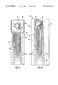
- FIG. 1 is a perspective view of an inkjet printing device which uses an exemplary disposable inkjet print cartridge with an integrated printhead and printhead wiper cleaning station which is constructed in accordance with the present invention
- FIG. 2 is an exemplary disposable print cartridge having an integrated inkjet printhead and printhead wiper station which may be used in the printing device of FIG. 1;
- FIG. 3 is another exemplary disposable print cartridge having an integrated inkjet printhead and printhead wiper station which may be used in the printing device of FIG. 1;
- FIG. 4 is a front face plan-view of the print cartridge of FIG. 2;
- FIG. 5 is an enlarged diagrammatic fragmentary cross sectional view taken at the line 5 — 5 of FIG. 4;
- FIG. 6 is an enlarged diagrammatic fragmentary cross sectional view taken at the line 6 — 6 of FIG. 4;
- FIG. 7 is a greatly enlarge front face plan view of a printhead of the print cartridge of FIG. 2;
- FIG. 8 is a greatly enlarged front face plan view similar to FIG. 7 of the printhead with portions removed for clarity of illustration;
- FIG. 9 is a diagrammatic fragmentary cross sectional view taken at the line 5 — 5 of FIG. 8, and is shown greatly enlarged in comparison to the illustration of FIG. 8;
- FIG. 10 is a diagrammatic cross sectional view of a portion of the printhead, and during a stage of the manufacturing process, and is similar to the portion seen in FIG. 9 .
- FIG. 1 there is illustrated an inkjet printing device, such as a transaction printer 10 that is constructed in accordance to the present invention.
- the transaction printer 10 is utilized for printing receipts and the like in typical commercial transactions.
- the transaction printer 10 is constructed for ease of use in a highly reliable manner requiring operator intervention only for the purpose of changing the consumables utilized in printing transaction receipts, such as a transaction receipt 12 illustrated in FIG. 1 .
- the printer 10 generally includes a base 14 for supporting therein a paper delivery system 18 and an ink delivery system 20 .
- the paper delivery system 18 moves a continuous roll of paper 22 through a print zone 24 , where ink is ejected onto the paper 22 from one or more disposable low profile inkjet printhead cartridges, such as a printhead cartridge 26 that forms part of the ink delivery system 20 .
- the ink delivery system 20 includes a print engine 28 for controlling the movement of a carriage cartridge stall 30 that travels along a slide bar 32 in a rectilinear path of travel adjacent to the print zone 24 .
- the print engine 28 also controls the ejecting of ink from the cartridge 26 to facilitate the forming of transaction receipts.
- the manner of controlling the movement of the carriage cartridge stall 30 and the manner of ejecting of ink from the cartridge 26 are well known to those skilled in the art of inkjet printing, the details of the print engine 28 will not be described hereinafter in greater detail.
- the paper delivery system 18 for moving the continuous roll of paper 22 through the print zone 24 is also well known to those skilled in the art of impact printers and thus, the paper delivery system 18 will not be described in greater detail.
- the cartridge stall 30 may accommodate either a single cartridge 26 for black ink printing or a pair of cartridges 26 for black and selected color printing.
- the inkjet printhead cartridge 26 generally includes a cartridge body 34 having a substantially hollow structure for holding a supply of ink.
- supply of ink provided in the cartridge 26 is a fast drying pigment ink that is provided in either black or a user selected color, such as magenta, cyan or yellow for example.
- the cartridge body 34 has a general box like structure that includes a rear wall 37 , a top wall 39 , a bottom wall 41 , a pair of side walls 43 and 44 respectively and a front wall 46 .
- a front face portion 36 Integrally formed to the front wall 46 and projecting outwardly therefrom is a front face portion 36 having a sloping top wall 71 terminating at a lower lip 65 .
- a lower portion of the front face portion 36 helps define an inkjet printhead wiper cleaning station 45 as will be described hereinafter in greater detail.
- An inkjet printhead 47 is mounted within a recessed channel area 42 on the front face portion 36 and is sandwiched between the wiper cleaning station 45 .
- the printing device 10 also includes a wiper assembly 38 and wiper 40 .
- the wiper assembly 38 is mounted to the paper delivery system 18 in such a manner to provide interference between the wiper 40 and the printhead cartridge 26 .
- the interference is also provided with the printhead 47 in order to remove any residue build up on and around a set of fine-dimensioned orifices 58 (FIG. 7) forming thereon.
- the interference of the wiper 40 with the printhead 47 is set to about between 0.25 millimeters to about 0.75 millimeters. A more preferred setting is between about 0.35 millimeters to about 0.60 millimeters, while the most preferred setting is set to about 0.50 millimeters.
- the wiper cleaning station 45 defined by the front face portion 36 of the printhead cartridge 26 makes certain that the wiper 40 is cleaned of accumulated debris each time the wiper 40 and the printhead 47 move relative to one another.
- the ink delivery system 20 further includes a sponge 48 that is carried within a chamber 50 defined by the hollow space within the interior of the cartridge body 34 .
- the sponge 48 is for holding the supply of ink within the interior of the cartridge body 34 .
- a standpipe (not shown) conveys the printing fluid from the chamber 50 to the printhead 47 .
- the printhead 47 generally includes a printed circuit 53 which electrically couples the printhead 47 via a set of circuit traces 54 and electrical contacts 56 with the print engine 28 . That is, the electrical contacts 56 individually make electrical contact with matching contacts on a flex circuit (not shown) to the carriage stall 30 , and provide for the electrical interface of the printhead 47 with the print engine 28 .
- Individual fine-dimension orifices, such as the orifices 58 of the printhead 47 eject fluid when appropriate control signals are applied to the contacts 56 by the print engine 28 .
- the fine-dimensioned orifices 58 are formed in a metallic plate member 62 that is adhesively attached to the floor of the recess area 42 of the underlying front face portion 36 of the printhead cartridge 26 .
- a through hole 66 is formed between front face portion 36 and a portion of the plate member 62 .
- the printhead cartridge 26 generally includes an integrally form outwardly projecting tab 35 for facilitating the installation and removal of the printhead cartridge 26 from the carriage stall 30 .
- the tab 35 is disposed on the rear wall 37 of the cartridge body 34 adjacent to the top 39 of the cartridge body 34 .
- a top bull feed lip 52 is integrally formed in the top wall 39 extends across substantially the entire width dimension W of the cartridge body 34 adjacent to the rear wall 37 .
- a bottom bull feed lip 60 is disposed adjacent the bottom of the rear wall 37 on the bottom wall 41 of the cartridge body 34 .
- the bottom bull feed lip 60 is about one half the width dimension of the top bull feed lip 52 .
- the top bull feed lip 52 and the bottom bull feed lip 60 cooperate with a bull feeder (not shown) to facilitate the proper orientation of the cartridge body 34 for manufacturing assembly purposes.
- the cartridge body 34 has integrally formed thereon a right side datum member 93 and left side datum member 95 .
- the datum members 93 and 95 are integrally formed on respective ones of the sides 43 and 44 .
- the respective datum members 93 and 95 extend across substantially the entire longitudinal dimension D of the walls 43 and 44 respectively.
- the datum members 93 and 95 are provided on the cartridge body 34 to further help facilitate the manufacturing of the printhead cartridge 26 by cooperating with the bull feeder to provide proper orientation of the cartridge body 34 for assembly purposes.
- the datum members 93 and 95 also help in the proper installation of the printhead cartridge 26 in the carriage stall 30 .
- the datum members 93 and 95 each extend outwardly from the front face portion 36 of the cartridge 26 to space the front face portion 36 from the cartridge stall 30 when the cartridge 26 is installed in the stall 30 . This spacing distance is selected to help provide a proper spacing between the orifices 58 and the paper 22 for printing purposes.
- the front face portion 36 includes a pair of spaced apart flex clip clearing slots 31 and 33 respectively.
- the slots 31 and 33 have a generally rectangular shaped and are disposed on opposite sides of the printhead 47 adjacent the glass substrate 73 .
- the flex clip clearing slots 31 and 33 permit the printhead cartridge 26 to rest in the carriage stall 30 without interfering with the flex cable clips (not shown) disposed therein.
- the elongated recess area 42 has a sufficient depth and width for receiving therein the printhead 47 .
- the printhead 47 when the printhead 47 is mounted within the recess 42 , the printhead 47 cooperates with a right sidewall 69 and a left sidewall 70 of the recess 42 to form a pair of debris accumulation channels 73 and 74 respectively.
- the channels 73 and 74 extend into a pair of recessed debris catchers 77 and 79 respectively each having a generally rectangular box like shape.
- the debris catchers 77 and 79 are closed on one end and open into respective channels 73 and 74 to permit debris flowing and falling down the channels under the force of gravity to accumulate within the catchers 77 and 79 .
- a pair of dams 67 and 68 block the respective channels 73 and 74 for helping to direct channel residual ink into the catchers 77 and 79 .
- the front face portion 36 further includes a pair of spaced sidewall members 81 and 83 that extend perpendicularly outwardly from the front wall 46 .
- the side wall members terminate in a pair of lips 85 and 87 respectively that are disposed adjacent to the recess 42 .
- the lips are disposed in a horizontal plane parallel to the printhead 47 but at a slightly higher elevation for facilitating the cleaning of the wiper 40 as it first engages a side wall member, such as the side wall member 81 and then a lip, such as the lip 87 .
- the respective ones of the lips 85 and 87 have a sufficient width to provide a cleaning surface for engaging the cleaning surfaces of the wiper 40 .
- the printhead cartridge 26 and wiper 40 will engage a first cleaning surface of the wiper 40 with side wall 81 .
- the first cleaning surface of the wiper 40 is scraped along a second cleaning surface provided by the lip surface 87 .
- This scraping action permits any debris on the first cleaning surface of the wiper 40 to fall and flow down the sidewall 81 onto a lower right side plateau 98 .
- the wiper 40 snaps into the channel 73 permitting any remaining wiper debris to fall freely down the channel 73 and into the debris accumulating catcher 77 .
- the wiper 40 travels across the orifices 58 of the printhead 47 to clean the orifices 58 with the cleaned wiping surface of the wiper 40 .
- the wiper 40 snaps off of the printhead 47 entering the opposite channel 74 permitting any debris removed from the printhead 47 to fall freely down the channel 74 to be accumulated in the channel 74 and the debris accumulating catcher 79 .
- the first cleaning surface of the wiper engages the wall 70 and then the lip surface 85 . This engagement and scraping action further cleans the first cleaning surface of the wiper allowing the debris to fall down the wall 70 , and the channel 74 for accumulation in the debris accumulating catcher 79 .
- the wiper 40 snaps into the space opposite side wall 83 allowing any remaining debris to fall under the force of gravity onto the outside lower left plateau 99 .
- the printhead cartridge 26 and wiper 40 will engage a second cleaning surface of the wiper 40 with side wall 83 .
- the second cleaning surface of the wiper 40 is scraped along a second cleaning surface provided by the lip surface 87 . This scraping action permits any debris on the second cleaning surface of the wiper 40 to fall and flow down the sidewall 83 onto the lower plateau 99 . From the lip surface 87 , the wiper 40 snaps into the channel 74 permitting any remaining wiper debris to fall freely down the channel 74 and into the debris accumulating catcher 79 .
- the wiper 40 travels across the orifices 58 of the printhead 47 to clean the orifices 58 with the cleaned second wiping surface of the wiper 40 .
- the wiper 40 snaps off of the printhead 47 entering the opposite channel 73 permitting any debris removed from the printhead 47 to fall freely down the channel 73 to be accumulated in the channel 73 and the debris accumulating catcher 77 .
- the first cleaning surface of the wiper engages the wall 69 and then the lip surface 87 .
- This engagement and scraping action further cleans the second cleaning surface of the wiper 40 allowing the debris to fall down the wall 69 , and the channel 73 for accumulation in the debris accumulating catcher 77 .
- the wiper 40 snaps into the space opposite side wall 81 allowing any remaining debris to fall under the force of gravity onto the outside plateau 98 .
- the above described cleaning action of the first cleaning surface of the wiper 40 and the second cleaning surface of the wiper 40 is repeated until the ink supply of the printhead cartridge 26 is spent. At this time the printhead cartridge 26 is replaced resulting in a new wiper station being provided.
- the cutout areas indicated generally at 55 and 57 on either side of the raised front face portion above plateaus 98 and 99 respectively allows the wiper to disengage from the printhead, which in-turn allow the linear translation of the printhead cartridge to be reversed without creating any substantial wiper wear.
- the cutout areas 55 and 57 also allow a centrally disposed service station to be placed in the printing device 10 thereby greatly reducing the overall width of the printing device 10 .
- the thermal inkjet printhead 47 includes a substrate 72 (FIGS. 9 - 10 ), which is most preferably formed as a plate of glass (i.e. an amorphous, generally non-conductive material). As seen in plan-view, the substrate 72 has a generally rectangular shape. Most preferably, the glass substrate is formed from an inexpensive type of soda/lime glass utilized in ordinary glass windows, which makes the printhead 47 very economical to manufacture. The printhead 47 is especially economical and inexpensive to manufacture when considered in comparison to printheads utilizing the conventional technologies that require a substrate of silicon or other crystalline semiconductor material.
- the thin-film structure 75 is formed substantially of plural thin-film layers applied one after the other and atop of one another, and each of which entirely covers and is congruent with the plan-view shape of the substrate 72 . Again, this plan-view shape of the substrate 72 is seen in FIGS. 7 and 8.
- subsequent patterning and etching operations are used to define the contacts 56 and printed circuit 53 , for example, as is described hereinafter in greater detail.
- the thin-film structure 75 includes a metallic heat sink and diffusion barrier thin-film layer 76 (FIGS. 5 and 6) which is applied upon the substrate 72 .
- the layer 76 covers the entire plan-view shape of the substrate 72 , and is preferably formed of chrome about 1 to 2 microns thick.
- the layer 76 may be formed of other metals and alloys.
- the thin-film heat sink and diffusion barrier layer 76 may be formed of gold, palladium, or platinum, or of alloys of these or other metals.
- the insulator layer 78 is preferably formed of silicon oxide, and is about 1 to 2 microns thick. Again, this insulator layer 78 covers and is congruent with the entire plan-view shape of the substrate 72 .
- a resistor thin-film layer 80 is formed on the substrate 72 and on the insulator layer 76 .
- the thin-film resistor layer 80 is preferably formed of tantalum, aluminum allow, and is preferably about 600 Angstroms thick.
- the resistor thin-film layer 80 is formed to cover and be congruent with the entire plan-view shape of the substrate 72 , but does not remain this extensive. That is, the resistor thin-film layer 80 is later patterned and etched back until it covers only an area congruent with the traces 54 of the printed circuit 53 , with each of the contacts 56 , and with each one of plural print resistor areas 82 (FIG. 9, and generally indicated with the arrowed number 82 on FIG. 8 ).
- the metallic conductor thin-film layer 84 is formed preferably of aluminum, and is about 0.5 microns thick. Again, this metallic conductor layer 84 is initially formed to cover and be congruent with the entire plan-view shape of the substrate 72 . However, the conductor layer 84 is also later patterned and etched back to cover only the area defining the traces 54 of the printed circuit 53 , and defining the contacts 56 . More particularly, the conductor layer 84 is first etched away at the location of the print resistors 82 so that a portion of the thin film resistor layer 60 spanning between traces 54 of the printed circuit 53 provides the only conduction path between these traces 54 .
- the etching operation is carried further, removing both the conductive layer 64 and the underlying resistive layer 60 over the entire plan-view shape of the substrate 72 , except at the locations of the traces 54 and contact pads 56 .
- This etching operation leaves the traces 54 and the contact pads 56 standing in relief on the insulative layer 78 , as can be appreciated from viewing FIG. 9 .
- the print resistors 82 are fine-dimension areas of the resistive layer 80 .
- the print resistors 82 can be caused to quickly dissipate energy, and to liberate heat.
- the metallic heat sink layer 76 cover substantially the entire plan-view shape of the substrate 72 , it will be understood that this heat sink layer 76 both underlies the resistors 82 to absorb heat from these resistors, and has a large area (i.e. essentially the entire plan-view area of the printhead 47 ) from which to dissipate excess heat.
- the printhead 47 during operation maintains a desirably low temperature, and can operate at firing repetition rates not hereto possible with conventional printheads using a glass substrate.
- a first manufacturing intermediate article 90 results from the above described manufacturing steps prior to the patterning and etching steps described above and prior to the formation of the through hole 66 .
- This first manufacturing intermediate article 90 includes the substrate 72 , and the thin-film layers 76 , 78 , 80 , and 84 , each of which substantially covers and is congruent with the entire plan-view shape of the substrate 72 .
- the first manufacturing intermediate article 90 is subjected to the patterning and etching processes described above to produce a second manufacturing intermediate article 92 , substantially as is seen in FIGS. 4 and 5.
- On the second manufacturing intermediate article 92 is formed a pair of passivating thin-film layers 86 (FIG. 9) and which is indicated on FIG.
- This passivating thin-film layer 86 includes a first sub-layer 88 of silicon nitride, followed by a second substrate layer 89 of silicon carbide. As seen in FIG. 9 fragmentarily, the completion of the printhead 47 requires only the adhesive attachment of the metallic plate member 44 , with the print orifices 58 in alignment with the print resistors 82 .
- the thin-film structure 74 may be formed on the substrate 72 using a variety of techniques.
- the work-piece that will become the first and second intermediate articles, and which will become the completed printhead 47 may be subjected to radio frequency energy.
- the second manufacturing intermediate article 92 is exposed to elevated temperatures and to radio frequency energy to assist in the deposition of the layers.
- the metallic heat sink layer 76 serves as a diffusion barrier to prevent migration of sodium from the soda/lime glass substrate 72 into the other thin layer structures of the printhead 47 .
- the sodium could cause a lesion in the passivation layer at which this layer would not long withstand the cavitation occurring in the printing fluid each time a bubble collapse after an ink jet droplet ejection.
- the heat sink layer 76 covers the entire plan-view shape of the printhead 47 , there is no place where sodium from the glass substrate 72 can migrate into the thin-film structures above the metallic heat sink layer 76 . Thus, contamination of the thin film structure 74 with sodium from the glass substrate 72 is prevented.
- the printhead cartridge 126 is substantially identical to printhead cartridge 26 except for the structure of the front face portion.
- the printhead cartridge 126 includes a cartridge body 134 that is integrally connected to a raised front face portion 136 .
- the raised front face portion 136 is substantially identical to the front face portion 36 except for its sidewall-outside plateau interconnection.
- the front face portion 136 includes a pair of sidewalls 181 and 183 respectively that extend upwardly from plateaus 198 and 199 respectively at an angle ⁇ , where the angle ⁇ is about 60 degrees.
- Each one of the sidewalls 181 and 183 terminate in a lip, such as a lip 185 and a lip 187 respectively. From the foregoing, it should be understood by those skilled in the art, that the wedge shaped sidewalls 181 and 183 commence engaging a tip portion of the wiper 40 first and then gradually engage the respective ones of the first cleaning surface and the second cleaning surface providing more of scraping action against such cleaning surfaces.
Landscapes
- Ink Jet (AREA)
Priority Applications (5)
| Application Number | Priority Date | Filing Date | Title |
|---|---|---|---|
| US09/472,716 US6302515B2 (en) | 1999-12-23 | 1999-12-23 | Transaction printing device having wiper debris collectors |
| DE60033771T DE60033771D1 (de) | 1999-12-23 | 2000-12-18 | Wischerschmutzsammler |
| EP00311298A EP1110734B1 (en) | 1999-12-23 | 2000-12-18 | Wiper debris collector |
| JP2000391922A JP2001205817A (ja) | 1999-12-23 | 2000-12-25 | ワイパデブリコレクタおよびトランザクションプリント装置 |
| US09/912,746 US6517186B1 (en) | 1999-12-23 | 2001-07-24 | Transaction printing device having wiper debris collectors |
Applications Claiming Priority (1)
| Application Number | Priority Date | Filing Date | Title |
|---|---|---|---|
| US09/472,716 US6302515B2 (en) | 1999-12-23 | 1999-12-23 | Transaction printing device having wiper debris collectors |
Related Child Applications (1)
| Application Number | Title | Priority Date | Filing Date |
|---|---|---|---|
| US09/912,746 Division US6517186B1 (en) | 1999-12-23 | 2001-07-24 | Transaction printing device having wiper debris collectors |
Publications (2)
| Publication Number | Publication Date |
|---|---|
| US20010013880A1 US20010013880A1 (en) | 2001-08-16 |
| US6302515B2 true US6302515B2 (en) | 2001-10-16 |
Family
ID=23876662
Family Applications (2)
| Application Number | Title | Priority Date | Filing Date |
|---|---|---|---|
| US09/472,716 Expired - Fee Related US6302515B2 (en) | 1999-12-23 | 1999-12-23 | Transaction printing device having wiper debris collectors |
| US09/912,746 Expired - Fee Related US6517186B1 (en) | 1999-12-23 | 2001-07-24 | Transaction printing device having wiper debris collectors |
Family Applications After (1)
| Application Number | Title | Priority Date | Filing Date |
|---|---|---|---|
| US09/912,746 Expired - Fee Related US6517186B1 (en) | 1999-12-23 | 2001-07-24 | Transaction printing device having wiper debris collectors |
Country Status (4)
| Country | Link |
|---|---|
| US (2) | US6302515B2 (https=) |
| EP (1) | EP1110734B1 (https=) |
| JP (1) | JP2001205817A (https=) |
| DE (1) | DE60033771D1 (https=) |
Cited By (6)
| Publication number | Priority date | Publication date | Assignee | Title |
|---|---|---|---|---|
| USD452875S1 (en) | 2000-07-14 | 2002-01-08 | Xerox Corporation | Positioning guide for an ink tank |
| US6517186B1 (en) * | 1999-12-23 | 2003-02-11 | Hewlett-Packard Company | Transaction printing device having wiper debris collectors |
| US6543878B2 (en) * | 1999-12-23 | 2003-04-08 | Hewlett-Packard Development Company, L.P. | Printhead cartridge with wiper cleaning station |
| US20040145626A1 (en) * | 2001-12-13 | 2004-07-29 | Jill Stauffer | Fluid ejection head |
| USD538337S1 (en) * | 2005-11-18 | 2007-03-13 | Brother Industries, Ltd. | Ink cartridge |
| USD587307S1 (en) * | 2007-11-28 | 2009-02-24 | Seiko Epson Corporation | Ink cartridge |
Families Citing this family (1)
| Publication number | Priority date | Publication date | Assignee | Title |
|---|---|---|---|---|
| JP5315700B2 (ja) * | 2008-01-18 | 2013-10-16 | セイコーエプソン株式会社 | サーマルプリンタ |
Citations (4)
| Publication number | Priority date | Publication date | Assignee | Title |
|---|---|---|---|---|
| US4709247A (en) * | 1986-12-22 | 1987-11-24 | Eastman Kodak Company | High resolution, print/cartridge ink, jet printer |
| US5025271A (en) * | 1986-07-01 | 1991-06-18 | Hewlett-Packard Company | Thin film resistor type thermal ink pen using a form storage ink supply |
| US5202702A (en) * | 1985-04-08 | 1993-04-13 | Canon Kabushiki Kaisha | Ink jet recording apparatus and a method of cleaning a recording head used in the apparatus |
| US5905513A (en) * | 1995-10-20 | 1999-05-18 | Lexmark International, Inc. | Ink jet printhead body having wiper cleaning zones located on both sides of printhead |
Family Cites Families (7)
| Publication number | Priority date | Publication date | Assignee | Title |
|---|---|---|---|---|
| JPH05169671A (ja) * | 1991-12-25 | 1993-07-09 | Seiko Epson Corp | インクジェット記録装置 |
| JP3324914B2 (ja) | 1995-08-30 | 2002-09-17 | ブラザー工業株式会社 | インクジェット記録装置 |
| US5774140A (en) * | 1995-10-31 | 1998-06-30 | Hewlett-Packard Company | Skip stroke wiping system for inkjet printheads |
| JP3329174B2 (ja) * | 1996-02-29 | 2002-09-30 | セイコーエプソン株式会社 | 多機能型印刷装置 |
| JP3428856B2 (ja) * | 1996-08-30 | 2003-07-22 | キヤノン株式会社 | インクジェット記録ヘッド及び該インクジェット記録ヘッドを搭載するインクジェット記録装置 |
| US6302515B2 (en) * | 1999-12-23 | 2001-10-16 | Hewlett-Packard Company | Transaction printing device having wiper debris collectors |
| US6367904B1 (en) * | 1999-12-23 | 2002-04-09 | Hewlett-Packard Company | Wiper cleaning apparatus and method of using same |
-
1999
- 1999-12-23 US US09/472,716 patent/US6302515B2/en not_active Expired - Fee Related
-
2000
- 2000-12-18 EP EP00311298A patent/EP1110734B1/en not_active Expired - Lifetime
- 2000-12-18 DE DE60033771T patent/DE60033771D1/de not_active Expired - Lifetime
- 2000-12-25 JP JP2000391922A patent/JP2001205817A/ja not_active Withdrawn
-
2001
- 2001-07-24 US US09/912,746 patent/US6517186B1/en not_active Expired - Fee Related
Patent Citations (4)
| Publication number | Priority date | Publication date | Assignee | Title |
|---|---|---|---|---|
| US5202702A (en) * | 1985-04-08 | 1993-04-13 | Canon Kabushiki Kaisha | Ink jet recording apparatus and a method of cleaning a recording head used in the apparatus |
| US5025271A (en) * | 1986-07-01 | 1991-06-18 | Hewlett-Packard Company | Thin film resistor type thermal ink pen using a form storage ink supply |
| US4709247A (en) * | 1986-12-22 | 1987-11-24 | Eastman Kodak Company | High resolution, print/cartridge ink, jet printer |
| US5905513A (en) * | 1995-10-20 | 1999-05-18 | Lexmark International, Inc. | Ink jet printhead body having wiper cleaning zones located on both sides of printhead |
Cited By (7)
| Publication number | Priority date | Publication date | Assignee | Title |
|---|---|---|---|---|
| US6517186B1 (en) * | 1999-12-23 | 2003-02-11 | Hewlett-Packard Company | Transaction printing device having wiper debris collectors |
| US6543878B2 (en) * | 1999-12-23 | 2003-04-08 | Hewlett-Packard Development Company, L.P. | Printhead cartridge with wiper cleaning station |
| USD452875S1 (en) | 2000-07-14 | 2002-01-08 | Xerox Corporation | Positioning guide for an ink tank |
| US20040145626A1 (en) * | 2001-12-13 | 2004-07-29 | Jill Stauffer | Fluid ejection head |
| US6820963B2 (en) | 2001-12-13 | 2004-11-23 | Hewlett-Packard Development Company, L.P. | Fluid ejection head |
| USD538337S1 (en) * | 2005-11-18 | 2007-03-13 | Brother Industries, Ltd. | Ink cartridge |
| USD587307S1 (en) * | 2007-11-28 | 2009-02-24 | Seiko Epson Corporation | Ink cartridge |
Also Published As
| Publication number | Publication date |
|---|---|
| US6517186B1 (en) | 2003-02-11 |
| US20010013880A1 (en) | 2001-08-16 |
| EP1110734B1 (en) | 2007-03-07 |
| DE60033771D1 (de) | 2007-04-19 |
| EP1110734A1 (en) | 2001-06-27 |
| JP2001205817A (ja) | 2001-07-31 |
Similar Documents
| Publication | Publication Date | Title |
|---|---|---|
| US6280014B1 (en) | Cleaning mechanism for inkjet print head with fixed gutter | |
| JP4299526B2 (ja) | 浮き部を有する薄膜メンブレンを設けたプリントヘッド | |
| US6302515B2 (en) | Transaction printing device having wiper debris collectors | |
| US6325485B2 (en) | Printhead cartridge with wiper cleaning station | |
| US6517187B1 (en) | Method and apparatus for cleaning residual ink from printhead nozzle faces | |
| US6367904B1 (en) | Wiper cleaning apparatus and method of using same | |
| EP0553975B1 (en) | Cleaning member used in an ink jet apparatus | |
| JPH04286655A (ja) | インクジェット記録装置 | |
| JP2804613B2 (ja) | インクジェット記録方法およびその装置 | |
| JP5087682B2 (ja) | 流体を噴射するための部品 | |
| JPH05201029A (ja) | インクヘッドの回復方法及びそれを実施する装置 | |
| JPH03136854A (ja) | インクジェット記録装置及び記録ヘッドユニット | |
| JP2000141677A (ja) | インクジェット記録ヘッド用クリ―ニング装置、インクジェット記録ヘッド用クリ―ニング方法、およびインクジェット記録装置 | |
| JP3249167B2 (ja) | カラーインクジェット記録装置 | |
| JPH03277555A (ja) | インクジェット記録装置 | |
| JP3251575B2 (ja) | カラーインクジェット記録装置 | |
| JPH04214359A (ja) | インクジェット記録装置 | |
| JPH04176652A (ja) | インクジェット記録装置 | |
| JP2860685B2 (ja) | インクジェット記録装置の回復方法 | |
| JPH0373351A (ja) | 液体噴射記録ヘッド用基体、該基体を用いた液体噴射記録ヘッド及び該液体噴射記録ヘッドを備えた液体噴射記録装置 | |
| JPH03136859A (ja) | クリーニング機構を備えた液体噴射記録装置 | |
| JPH07246709A (ja) | インクジェット記録装置 | |
| JPH06270415A (ja) | インクジェット記録装置 | |
| WO2006121975A1 (en) | Fluid ejection assembly | |
| JP2005041191A (ja) | インクジェット記録装置および回復方法 |
Legal Events
| Date | Code | Title | Description |
|---|---|---|---|
| AS | Assignment |
Owner name: HEWLETT-PACKARD COMPANY, COLORADO Free format text: ASSIGNMENT OF ASSIGNORS INTEREST;ASSIGNORS:WOLF, FREDERICK ANDREW;XU, YINAN;REEL/FRAME:010647/0557;SIGNING DATES FROM 20000203 TO 20000207 |
|
| FPAY | Fee payment |
Year of fee payment: 4 |
|
| FPAY | Fee payment |
Year of fee payment: 8 |
|
| AS | Assignment |
Owner name: HEWLETT-PACKARD DEVELOPMENT COMPANY, L.P., TEXAS Free format text: ASSIGNMENT OF ASSIGNORS INTEREST;ASSIGNOR:HEWLETT-PACKARD COMPANY;REEL/FRAME:026945/0699 Effective date: 20030131 |
|
| REMI | Maintenance fee reminder mailed | ||
| LAPS | Lapse for failure to pay maintenance fees | ||
| STCH | Information on status: patent discontinuation |
Free format text: PATENT EXPIRED DUE TO NONPAYMENT OF MAINTENANCE FEES UNDER 37 CFR 1.362 |
|
| FP | Lapsed due to failure to pay maintenance fee |
Effective date: 20131016 |