US6269065B1 - Recording medium and recording/reproduction apparatus thereof - Google Patents
Recording medium and recording/reproduction apparatus thereof Download PDFInfo
- Publication number
- US6269065B1 US6269065B1 US08/692,518 US69251896A US6269065B1 US 6269065 B1 US6269065 B1 US 6269065B1 US 69251896 A US69251896 A US 69251896A US 6269065 B1 US6269065 B1 US 6269065B1
- Authority
- US
- United States
- Prior art keywords
- layer
- recording
- data
- recording medium
- format
- Prior art date
- Legal status (The legal status is an assumption and is not a legal conclusion. Google has not performed a legal analysis and makes no representation as to the accuracy of the status listed.)
- Expired - Lifetime
Links
- 238000005070 sampling Methods 0.000 claims abstract description 81
- 230000005236 sound signal Effects 0.000 claims description 44
- 238000013139 quantization Methods 0.000 claims description 4
- 238000010586 diagram Methods 0.000 description 9
- 238000001228 spectrum Methods 0.000 description 5
- 238000012545 processing Methods 0.000 description 4
- 239000011347 resin Substances 0.000 description 4
- 229920005989 resin Polymers 0.000 description 4
- 230000001360 synchronised effect Effects 0.000 description 4
- XAGFODPZIPBFFR-UHFFFAOYSA-N aluminium Chemical compound [Al] XAGFODPZIPBFFR-UHFFFAOYSA-N 0.000 description 3
- 229910052782 aluminium Inorganic materials 0.000 description 2
- 238000006243 chemical reaction Methods 0.000 description 2
- 238000012937 correction Methods 0.000 description 2
- 238000000034 method Methods 0.000 description 2
- 238000004544 sputter deposition Methods 0.000 description 2
- 238000012546 transfer Methods 0.000 description 2
- 238000013459 approach Methods 0.000 description 1
- 230000015556 catabolic process Effects 0.000 description 1
- 238000006731 degradation reaction Methods 0.000 description 1
- 239000003989 dielectric material Substances 0.000 description 1
- 238000001914 filtration Methods 0.000 description 1
- 238000004519 manufacturing process Methods 0.000 description 1
- 238000013507 mapping Methods 0.000 description 1
- 238000012986 modification Methods 0.000 description 1
- 230000004048 modification Effects 0.000 description 1
- 229920000515 polycarbonate Polymers 0.000 description 1
- 239000004417 polycarbonate Substances 0.000 description 1
- 230000001681 protective effect Effects 0.000 description 1
- 238000007493 shaping process Methods 0.000 description 1
- 239000000758 substrate Substances 0.000 description 1
- 230000000007 visual effect Effects 0.000 description 1
Images


Classifications
-
- G—PHYSICS
- G11—INFORMATION STORAGE
- G11B—INFORMATION STORAGE BASED ON RELATIVE MOVEMENT BETWEEN RECORD CARRIER AND TRANSDUCER
- G11B20/00—Signal processing not specific to the method of recording or reproducing; Circuits therefor
- G11B20/10—Digital recording or reproducing
- G11B20/10527—Audio or video recording; Data buffering arrangements
-
- G—PHYSICS
- G11—INFORMATION STORAGE
- G11B—INFORMATION STORAGE BASED ON RELATIVE MOVEMENT BETWEEN RECORD CARRIER AND TRANSDUCER
- G11B19/00—Driving, starting, stopping record carriers not specifically of filamentary or web form, or of supports therefor; Control thereof; Control of operating function ; Driving both disc and head
- G11B19/02—Control of operating function, e.g. switching from recording to reproducing
- G11B19/12—Control of operating function, e.g. switching from recording to reproducing by sensing distinguishing features of or on records, e.g. diameter end mark
-
- G—PHYSICS
- G11—INFORMATION STORAGE
- G11B—INFORMATION STORAGE BASED ON RELATIVE MOVEMENT BETWEEN RECORD CARRIER AND TRANSDUCER
- G11B19/00—Driving, starting, stopping record carriers not specifically of filamentary or web form, or of supports therefor; Control thereof; Control of operating function ; Driving both disc and head
- G11B19/20—Driving; Starting; Stopping; Control thereof
- G11B19/26—Speed-changing arrangements; Reversing arrangements; Drive-transfer means therefor
-
- G—PHYSICS
- G11—INFORMATION STORAGE
- G11B—INFORMATION STORAGE BASED ON RELATIVE MOVEMENT BETWEEN RECORD CARRIER AND TRANSDUCER
- G11B7/00—Recording or reproducing by optical means, e.g. recording using a thermal beam of optical radiation by modifying optical properties or the physical structure, reproducing using an optical beam at lower power by sensing optical properties; Record carriers therefor
- G11B7/007—Arrangement of the information on the record carrier, e.g. form of tracks, actual track shape, e.g. wobbled, or cross-section, e.g. v-shaped; Sequential information structures, e.g. sectoring or header formats within a track
- G11B7/013—Arrangement of the information on the record carrier, e.g. form of tracks, actual track shape, e.g. wobbled, or cross-section, e.g. v-shaped; Sequential information structures, e.g. sectoring or header formats within a track for discrete information, i.e. where each information unit is stored in a distinct discrete location, e.g. digital information formats within a data block or sector
-
- G—PHYSICS
- G11—INFORMATION STORAGE
- G11B—INFORMATION STORAGE BASED ON RELATIVE MOVEMENT BETWEEN RECORD CARRIER AND TRANSDUCER
- G11B7/00—Recording or reproducing by optical means, e.g. recording using a thermal beam of optical radiation by modifying optical properties or the physical structure, reproducing using an optical beam at lower power by sensing optical properties; Record carriers therefor
- G11B7/24—Record carriers characterised by shape, structure or physical properties, or by the selection of the material
-
- G—PHYSICS
- G11—INFORMATION STORAGE
- G11B—INFORMATION STORAGE BASED ON RELATIVE MOVEMENT BETWEEN RECORD CARRIER AND TRANSDUCER
- G11B23/00—Record carriers not specific to the method of recording or reproducing; Accessories, e.g. containers, specially adapted for co-operation with the recording or reproducing apparatus ; Intermediate mediums; Apparatus or processes specially adapted for their manufacture
- G11B23/0014—Record carriers not specific to the method of recording or reproducing; Accessories, e.g. containers, specially adapted for co-operation with the recording or reproducing apparatus ; Intermediate mediums; Apparatus or processes specially adapted for their manufacture record carriers not specifically of filamentary or web form
- G11B23/0021—Record carriers not specific to the method of recording or reproducing; Accessories, e.g. containers, specially adapted for co-operation with the recording or reproducing apparatus ; Intermediate mediums; Apparatus or processes specially adapted for their manufacture record carriers not specifically of filamentary or web form discs
-
- G—PHYSICS
- G11—INFORMATION STORAGE
- G11B—INFORMATION STORAGE BASED ON RELATIVE MOVEMENT BETWEEN RECORD CARRIER AND TRANSDUCER
- G11B23/00—Record carriers not specific to the method of recording or reproducing; Accessories, e.g. containers, specially adapted for co-operation with the recording or reproducing apparatus ; Intermediate mediums; Apparatus or processes specially adapted for their manufacture
- G11B23/30—Record carriers not specific to the method of recording or reproducing; Accessories, e.g. containers, specially adapted for co-operation with the recording or reproducing apparatus ; Intermediate mediums; Apparatus or processes specially adapted for their manufacture with provision for auxiliary signals
- G11B23/36—Signals on record carriers or on containers and recorded by the same method as the main recording
-
- G—PHYSICS
- G11—INFORMATION STORAGE
- G11B—INFORMATION STORAGE BASED ON RELATIVE MOVEMENT BETWEEN RECORD CARRIER AND TRANSDUCER
- G11B7/00—Recording or reproducing by optical means, e.g. recording using a thermal beam of optical radiation by modifying optical properties or the physical structure, reproducing using an optical beam at lower power by sensing optical properties; Record carriers therefor
- G11B7/004—Recording, reproducing or erasing methods; Read, write or erase circuits therefor
- G11B7/0045—Recording
-
- G—PHYSICS
- G11—INFORMATION STORAGE
- G11B—INFORMATION STORAGE BASED ON RELATIVE MOVEMENT BETWEEN RECORD CARRIER AND TRANSDUCER
- G11B7/00—Recording or reproducing by optical means, e.g. recording using a thermal beam of optical radiation by modifying optical properties or the physical structure, reproducing using an optical beam at lower power by sensing optical properties; Record carriers therefor
- G11B7/004—Recording, reproducing or erasing methods; Read, write or erase circuits therefor
- G11B7/005—Reproducing
Definitions
- This invention relates generally to a recording medium for recording audio data in a new data format and, more specifically, to a two-layered recording medium.
- CDs Compact disks
- the CD which is referred to hereinafter as the first generation CD
- the first approach to be considered is increasing the sampling frequency
- the new CD cannot be reproduced using a player for the first generation CD, so that such a new CD is not sufficient as a new CD system.
- a player for the new CD system can be constructed to play back the first generation CD, however, to perform such playback, two series of digital playback circuits performing the functions of a decoder and a D/A converter for the first generation CD and a decoder and a D/A converter for the new CD system are necessary.
- a clock generator is also required for each circuit.
- Such added circuitry results in a complex, large sized, and expensive circuit structure of the playback device. Therefore, it is not a suitable solution to the problem of improving CD sound quality.
- the recording layer is structured to have a plurality of layers comprising at least a first layer and a second layer, wherein on the first layer an audio data program recorded in the first data format, and on the second layer the audio data program recorded in the second data format.
- the audio data program recorded on the first layer and the second layer is the same program.
- the data recorded, for example, on the first layer which is readable on a playback device for the first generation recording medium is provided with a data format of the first generation recording medium for playback on a conventional playback device, on the other hand, when the recording medium is used on a playback device for the new system, the data recorded on the second layer on which data of a high sound quality format is recorded is read out to play back high-quality sound.
- the present invention provides a high sound quality media as a new recording medium system, and also the present invention provides the convenience of compatibility with conventional playback devices.
- the second data format is provided with a sampling frequency that is an integral multiple of the sampling frequency of the first data format, the integral multiple relationship allows the structure of the compatible device for playing back the first generation recording medium and the recording medium of the present invention to be very simple.
- the second data format is prescribed to the one-bit ⁇ modulated signal, whereby it is possible to increase remarkably the sampling frequency and sufficiently high sound quality is realized.
- data recorded on the layer that is readable by a playback player for the first generation recording medium is rendered in the data format for the first generation recording medium and the data is regenerated or reproduced using a conventional playback device, and a playback device for the new system reads data on the second layer on which high sound quality format data are recorded, thus, high sound quality playback is realized.
- a sampling frequency that is an integral multiple of that of the first data format is assigned to the second data format, so that the possibly complex structure of the compatible device for playback of both the first generation recording medium and the new recording medium of the present invention is avoided.
- FIGS. 1A and 1B are schematic diagrams for illustrating a recording medium of an embodiment of the present invention.
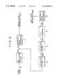
- FIG. 2 is a block diagram for illustrating recording of a recording medium according to an embodiment of the present invention.
- FIGS. 3A-3D are graphs for describing the frequency spectrum at each processing step of the recorded signal according to an embodiment of the present invention.
- FIG. 4 is a schematic diagram for illustrating a playback apparatus for a second generation disk according to an embodiment of the present invention.
- FIG. 5 is a schematic diagram for illustrating a playback apparatus for a second generation disk according to an embodiment of the present invention in which conventional data is reproduced.
- FIG. 6 is a schematic diagram for illustrating a playback apparatus for a second generation disk according to an embodiment of the present invention that is compatible with both first and second generation disks.
- Embodiments of the recording medium of the present invention will be described in detail referring to FIGS. 1 to 6 hereinafter.
- the first generation sampling frequency of 44.1 kHz is referred to as fs and the 2.8224 MHZ sampling frequency is referred to hereinafter as 64 fs.
- a one-bit ⁇ modulated digital audio signal with a 64 fs sampling frequency is applied as the digital audio signal for recording.
- This new CD recording medium is referred to as the second generation CD hereinafter.
- the one-bit ⁇ modulated signal can be provided with significantly higher frequencies compared with the data capacity and the data transfer rate in the conventional PCM modulated signal.
- a sampling frequency of 64 fs it is possible in principle to record and playback data high-frequency components up to 1.4 MHZ.
- the second generation CD has a remarkably high sound quality compared with the conventional first generation CD.
- the second generation CD also has a diameter of approximately 12 cm, and the visual appearance of the second generation CD is the same as that of the first generation CD.
- the sampling frequency of the second generation CD is selected as an integral multiple of the sampling frequency of the first generation CD, thereby symmetry between the second generation CD system and the first generation CD system is provided, and the compatibility is maintained for convenience and economy.
- the second generation CD recording medium in accordance with the present invention records not only audio data having 64 fs sampling/one-bit ⁇ modulated format but also audio data having the same format as the first generation CD.
- the audio data having the 64 fs sampling/one-bit ⁇ modulated format is referred to as “high sampling data”, whereas on the other hand the audio data having the 44.1 kHz sampling/16-bit quantized first generation CD format is referred to as “normal.”
- an ultra-violet hardening resin is cast on the reflection film to form an intermediate layer I with a thickness of about 40 ⁇ m, and the resin is pressed using a stamper to form a pit P 1 in the first layer L 1 , while the resin is irradiated with ultraviolet rays to harden.
- an aluminum (A 1 ) reflection film R 1 is formed by sputtering and a protective film H of an ultra-violet hardening resin is formed thereover.
- the above-mentioned second generation CD has a diameter of 12 cm and thickness of 1.2 mm and is provided with a double-layered recording area, and has a track pitch of 0.74 ⁇ m and a recording capacity of about 4.7 G bytes per one layer, for a total of about 8.5 G bytes. Furthermore, in an alternative to the above-mentioned disk having a double layered recording area on one side, a disk having a diameter of 12 cm and thickness of 1.2 mm with recording areas on both sides of the disk but with different formats and having a track pitch of 0.74 ⁇ m and a recording capacity of the total 9.4 G bytes is also possible as a form of the second generation CD.
- FIG. 2 is a block diagram of a portion of the recording system used in the manufacturing of the second generation CD.
- An analog audio signal comprising an original audio signal from a master tape is fed in at terminal 10 .
- the frequency spectrum of such an analog audio signal is shown in FIG. 3 A.
- the analog audio signal is converted to digital data by ⁇ modulation using a one-bit A/D converter 11 , wherein the sampling frequency is changed to 64 fs and a digital audio signal of 64 fs/one-bit format is output.
- the frequency spectrum of this digital audio signal of 64 fs/one-bit format is shown in FIG. 3 B.
- the quantized noise components are concentrated in the high-frequency region on the frequency axis, because of the noise shaping function in ⁇ modulation.
- the digital audio signal of the 64 fs/one-bit format is fed to a recording signal processor 17 and modulated to a recording signal as it is.
- the 64 fs/one-bit signal is used as the digital audio data to be recorded.
- modulation processing for adding an error correction code and forming Eight-Fourteen modulation (EFM) is performed, and signals corresponding to the bit information actually formed on the disk are generated as the recording signals.
- the recording signal is a signal to be recorded on the second layer L 2 of the disk 1 , and the signal is a recording signal based on digital audio data consisting of the high sampling data of the 64 fs/one-bit format, and is the data to be recorded as pit P 2 shown in FIG. 1 B.
- the frequency spectrum of the digital data of the 2 fs/24-bit format is shown in FIG. 3 C. As shown therein, the sampling frequency is cut off at 2 fs, and data components in a frequency band up to the frequency of fs remain.
- the sampling frequency is changed to ⁇ fraction (1/64) ⁇ of the sampling frequency used in the ⁇ modulation, however, this operation is not what is typically called sampling rate conversion, but rather is a completely synchronous digital filtering for performing decimation in a ratio of 64:1. Therefore, there is no cause for generating jitter.
- the digital data of the fs/24-bit format are converted to data with 16 quantized bits by a bit mapping device 14 and fed to a sound recording signal processor 15 .
- necessary processing such as the addition of an error correction code and performing Eight-Fourteen modulation (EFM) is performed on the digital audio signal of the fs/16-bit format to generate a recording signal.
- EFM Eight-Fourteen modulation
- This recording signal is the signal to be recorded on the first layer L 1 . More specifically, this signal is a recording signal based on digital audio data comprising the normal data of the fs/16 bit format, and then is recorded as pit P 1 shown in FIG. 1 B.
- such a disk 1 as the second generation CD can be used not only for playback of high sound quality on a playback device matching the format of the second generation CD as described, but also for playback of the sound quality of the first generation CD level on a playback device matching the format of the first generation CD.
- the sampling frequency of the high sampling data is an integral multiple of that of the normal data, that is, the first generation CD, therefore, the data recorded on the first layer of the disk 1 is not inferior to the first generation CD in sound quality. More specifically, the sampling frequency is converted through the decimation filter processing without using a sampling rate converter, so that the jitter usually accompanying sampling rate conversion is not generated, therefore, a sound quality of the same level as that obtained when an analog audio signal is sampled directly at 44.1 kHz is obtained.
- FIG. 4 is a block diagram of a system for the playback of the disk 1 on a playback device matching the format of the second generation CD.
- the disk 1 is driven rotationally by a spindle motor 26 .
- the spindle motor 26 is driven at a constant linear velocity responding to a driving signal generated from a motor controller 25 .
- the disk 1 is rotated and simultaneously a pickup 21 irradiates a laser beam on the record surface of the disk 1 .
- the reflected beam is detected by the pickup 21 in order to read the information in the pits formed on the disk 1 .
- the focus point of the pickup 21 is set so as to be on the second layer L 2 , and the wave-length of the laser beam from the pickup 21 is selected so that the laser beam is reflected by the reflection film R 2 , as shown in FIG. 1B, the information recorded as pits P 2 on the second layer L 2 is read by the pickup 21 .
- the information read by the pickup 21 is fed to the high sampling data decoder 29 .
- the high sampling data decoder 29 performs the decoding of the digital audio signal of the 64 fs/one-bit format.
- the clock signal CK 2 having a frequency used for decoding the high sampling data, namely the second generation CD, is generated by the oscillator 23 , and the clock signal CK 2 is fed to the high sampling data decoder 29 and to a one-bit D/A converter 33 .
- the pit information from the second layer L 2 extracted by the pickup 21 is decoded by the high sampling data decoder 29 , so that the digital audio signal of 64 fs/one-bit format is decoded.
- the resultant digital audio signal of the 64 fs/one-bit format is fed to the one-bit D/A converter 33 to convert it to an analog audio signal for output at terminal 34 .
- the high sound quality playback sound from the second generation CD is obtained.
- FIG. 5 is a block diagram illustrating a system for the playback of the disk 1 on a playback device for the first generation CD.
- the disk 1 is driven rotationally by the spindle motor 26 , and the spindle motor 26 is driven at a constant linear velocity in response to a driving signal from the motor controller 25 .
- a clock signal CK 1 from an oscillator 35 is divided using a frequency divider 36 to obtain the standard clock signal CKs with a prescribed frequency that corresponds to the disk rotation speed matching the format of the first generation CD. Then, the standard clock signal CKs and PLL clock signal CKd that is synchronous with the playback data are compared to generate an error signal. Power is applied to the spindle motor 26 corresponding to the error signal to activate the constant linear velocity servo.
- the PLL clock signal CKd is generated by feeding the data extracted in a normal data decoder 28 to the PLL circuit.
- the disk 1 is rotated and simultaneously a pickup 39 irradiates a laser beam on the record surface of the disk 1 , and the reflected beam is detected by the pickup 39 in order to read the information in the pits formed on the disk 1 .
- the laser beam of the pickup 39 for the first generation CD has a wavelength which passes through the semi-transparent reflection film R 2 shown in FIG. 1B, therefore, the laser beam is reflected from the aluminum reflection film R 1 . In this way, the information formed as pits P 1 on the first layer L 1 is read by the pickup 39 .
- the information read by the pickup 39 is fed to the normal data decoder 28 .
- the normal data decoder 28 is the part of the system that decodes the digital audio signal of the fs/16-bit format from the pit information.
- the clock signal CK 1 of the frequency used for decoding the first generation CD, namely the normal data, is generated from the oscillator 35 , and then the clock signal CK 1 is fed to the normal data decoder 28 and to a standard D/A converter 37 .
- the pit information on the first layer L 1 that is extracted by the pickup 39 is decoded using the normal data decoder 28 , thereby the digital audio signal of the fs/16-bit format is decoded.
- This decoded digital audio signal of the fs/16-bit format is fed to the D/A converter 37 and then converted to the analog audio signal fed out at terminal 34 .
- the disk 1 of the second generation CD can be also played back on a playback device for the first generation CD.
- the sound quality of the playback sound is the same as that of the first generation CD, and the sound quality will not be degraded.
- FIG. 6 shows a block diagram illustrating the playback of the second generation CD on a playback device that matches the formats for both the first generation CD and the second generation CD.
- FIG. 6 comprising the disk 1
- a first generation CD having a single layered structure equivalent to the first layer L 1 may also be mounted.
- the spindle motor 26 for rotationally driving the disk 1 is driven at a constant linear velocity in response to the driving signal from the motor controller 25 .
- the standard clock signal CKs of a prescribed frequency is obtained by dividing the clock signal CK 2 from the oscillator 23 using the frequency divider 24 .
- the standard clock signal CKs and the PLL clock signal CKd synchronous with the playback data are compared in the motor controller 25 to generate an error signal. Power is applied to the spindle motor 26 corresponding to the error signal to activate the constant linear velocity servo.
- the PLL clock signal CKd is generated by feeding the data extracted in the normal data decoder 28 or the high sampling data decoder 29 to the PLL circuit (not shown).
- the disk 1 is rotated and simultaneously the pickup 21 irradiates a laser beam on the record surface of the disk 1 , and the information recorded in the pits formed on the disk 1 is read.
- the focus point of the pickup 21 is selectively adjustable to focus F 2 on the second layer L 2 or to focus F 1 on the first layer L 1 by an adjusting signal from a focus controller 38 . Therefore, when the disk 1 is a disk of the second generation CD having a double-layered structure, as shown in FIG. 6, not only the pit information on the second layer L 2 having the high tone quality data but also the pit information on the first layer L 1 can be read. When the disk 1 is a first generation CD, of course, the focus is adjusted so as to be on the pit data of the first or only layer.
- the information read by the pickup 21 is fed to the high sampling data decoder 29 and to the normal data decoder 28 .
- the clock signal CK 2 from the oscillator 23 has a frequency for decoding the high sampling data, and the clock signal CK 2 is fed to the high sampling data decoder 29 .
- the clock signal CK 2 from the oscillator 23 is converted to the clock signal CK 1 of a frequency used for decoding the normal data by a frequency divider 27 , and the clock signal CK 1 is fed to the normal data decoder 28 .
- a digital audio signal with a sampling frequency of 64 fs/one bit format is output as the decoded signal from the high sampling data decoder 29 , and the output is fed to an input terminal T 2 of a switch 32 .
- a digital audio signal with a sampling frequency of fs/16 bit format is output as the decoded signal from the normal data decoder 28 , and the output is converted to the digital audio signal with a sampling frequency of 64 fs/one bit format through an over sampling digital filter 30 and a ⁇ modulation circuit 31 .
- the digital audio signal output from the ⁇ modulation circuit 31 is fed to an input terminal T 1 of the switch 32 .
- the selected output from the switch 32 is fed to the one-bit D/A converter 33 to convert the output to the analog audio signal made available at terminal 34 .
- the clock signal CK 2 which is the same clock signal as that for the high sampling data decoder 29 , is also fed to the one-bit D/A converter 33 .
- a disk judging section 22 judges whether the disk that has been mounted is a first generation CD or a second generation CD. This judgment is made possible by reading the table of contents (TOC) data recorded on the innermost periphery of the disk, regardless of its generation.
- TOC table of contents
- the disk judging section 22 controls the switch 32 , the dividing ratio of the frequency divider 24 , and the focus controller 38 depending on the results of the judgment.
- the playback device is operated as described as follows when the disk 1 to be regenerated or played back is a second generation CD having a double-layered structure, as shown in FIG. 6 .
- the disk judging section 22 judges whether the disk is a second generation CD based on the TOC data of the disk 1 and, if so, the dividing ratio of the frequency divider 24 is set to a value that corresponds to the second generation CD; the output of the switch 32 is connected to the input terminal T 2 ; and the focus controller 38 is set to the condition F 2 for focusing the beam on the second layer L 2 .
- the dividing ratio of the frequency divider 24 is prescribed to a value that corresponds to the second generation CD, whereby the frequency of the standard clock signal CKs used for the constant linear velocity servo of the motor controller 25 is converted to a frequency for the second generation CD.
- the disk 1 is driven rotationally at a constant liner velocity matching the requirements of the second generation CD.
- the pit information on the second layer L 2 extracted by the pickup 21 is decoded by the high sampling data decoder 29 , so that the digital audio signal of 64 fs/one-bit format is decoded and fed to the switch 32 .
- the output of the switch 32 is connected to the input terminal T 2 , and the digital audio signal of the 64 fs/one-bit format is fed to the one-bit D/A converter 33 and converted to the analog audio signal for output at terminal 34 .
- the playback device is operated as described as follows when the disk 1 to be regenerated or played back is a first generation CD.
- the disk judging section 22 judges whether the disk is the first generation CD based on the TOC data of the disk 1 , and the dividing ratio of the frequency divider 24 is set to a value that corresponds to the first generation CD; the output of the switch 32 is connected to the input terminal T 1 ; and the focus controller 38 is set to the condition F 1 for focusing the laser beam on the first layer L 1 .
- the special control for selecting the first layer is unnecessary, and the point focusing of the known kind by the focus search/servo operation is sufficient for the first generation CD.
- the dividing ratio of the frequency divider 24 is prescribed to a value that corresponds to the first generation CD, so that the frequency of the standard clock signal CKs used for the constant linear velocity servo of the motor controller 25 is converted to a frequency for the first generation CD.
- the disk 1 is driven rotationally at a constant liner velocity matching the requirements of the format of the first generation CD.
- the pit information extracted by the pickup 21 is decoded by the normal data decoder 28 , so that the digital audio signal of fs/16-bit format is decoded.
- the digital audio signal of the fs/16-bit format that has been decoded is converted to the digital audio signal of 64 fs/one bit format by the over sampling digital filter 30 and the ⁇ modulation circuit 31 , both of which are operated with the signal clock CK 2 .
- the output of the ⁇ modulator 31 is fed to input terminal T 1 of the switch 32 .
- the output of the switch 31 is connected to the input terminal T 1 under control of the disk judging section 22 , and the digital audio signal of the 64 fs/one-bit format is fed to the one-bit D/A converter 33 , and converted to the analog audio signal available at terminal 34 .
- the playback device of this type if the mounted disk 1 is judged by the disk judging section 22 as a second generation CD having a double-layered structure, it is possible to extract and playback the pit data on the first layer.
- the dividing ratio of the frequency divider 24 is set to a value that corresponds to the first generation CD, and the output of the switch 32 is connected to the input terminal T 1 .
- the pickup 21 is set to the condition F 1 for focusing on the first layer.
- the pit information on the first layer read by the pickup 21 is decoded by the normal data decoder 28 to convert the pit information to the digital audio signal of the fs/16 bit format.
- the digital audio signal of fs/16-bit format is converted to the digital audio signal of 64 fs/one bit format by the over-sampling filter 30 and ⁇ modulation circuit 31 .
- the audio signal of 64 fs/one bit format is fed to the one-bit D/A converter 33 through the input terminal T 1 and the output of the switch 32 and converted to the analog audio signal output.
- the playback device shown in FIG. 6 which is capable of the above-mentioned operations, the data on the second layer L 2 of the disk of the second generation CD is regenerated, thereby the high sound quality playback of audio data of the 64 fs format is realized.
- the sampling frequency of the high sampling data recorded on the second layer L 2 is prescribed to be an integral multiple of the sampling frequency of the normal data recorded on the first layer L 1 and first generation CD, thereby the playback device, as shown in FIG. 6, that is compatible with the first generation CD can be realized without using a seriously complex clock system.
- the ratio of sampling frequency of the high sampling data and the normal data is prescribed to a ratio of integers, so that the clock signal generated from the oscillator 23 is used commonly.
- a clock having a required frequency is easily generated using only a frequency divider without the need for a plurality of oscillators. Therefore, it is not necessary to structure two independent master clock systems, and this embodiment allows the clock system circuit to be constructed simply.
- the one-bit D/A converter 33 can be used commonly, so that the playback system circuit can be structured simply and without degradation in sound quality.
- the one-bit D/A converter 33 is a D/A converter which is operated corresponding to playback data of the high sampling data.
- the data of fs/16 bit format generated from the normal data decoder 28 should be converted to the data of the 64 fs/one bit format.
- the sampling frequencies are in the relationship of an integral multiple, the data is subjected to the 64 times over-sampling through the over-sampling filter 30 , and the data is converted to one-bit format through the ⁇ modulation circuit 31 , these two operations are sufficient for satisfying the requirement. Therefore, it is not necessary to use a sampling rate converter and not using a sampling rate converter eliminates the cause of jitter generation.
- the embodiment described hereinabove refers to the first generation CD as the current CD system and to the second generation CD matched to the first generation CD, however, the present invention is applied to not only a CD system but also other systems.
- a record playback system which is applied with a sampling frequency of an integral multiple of 44.1 kHz is realized.
- a second generation system having sampling frequencies of 32 kHz ⁇ n, or 48 kHz ⁇ n, where n represents an integer, can be structured.
- 48 kHz sampling data can be recorded on the first layer and 96 kHz sampling data can be recorded on the second layer.
- the recording layer structure of a recording medium may also be a structure comprising three layers or more layers.
Applications Claiming Priority (2)
| Application Number | Priority Date | Filing Date | Title |
|---|---|---|---|
| JP7-222749 | 1995-08-09 | ||
| JP22274995A JP3674092B2 (ja) | 1995-08-09 | 1995-08-09 | 再生装置 |
Publications (1)
| Publication Number | Publication Date |
|---|---|
| US6269065B1 true US6269065B1 (en) | 2001-07-31 |
Family
ID=16787312
Family Applications (2)
| Application Number | Title | Priority Date | Filing Date |
|---|---|---|---|
| US08/692,518 Expired - Lifetime US6269065B1 (en) | 1995-08-09 | 1996-01-05 | Recording medium and recording/reproduction apparatus thereof |
| US08/824,270 Expired - Lifetime US5706269A (en) | 1995-08-09 | 1997-03-26 | Recording medium and recording/reproduction apparatus therefor |
Family Applications After (1)
| Application Number | Title | Priority Date | Filing Date |
|---|---|---|---|
| US08/824,270 Expired - Lifetime US5706269A (en) | 1995-08-09 | 1997-03-26 | Recording medium and recording/reproduction apparatus therefor |
Country Status (7)
| Country | Link |
|---|---|
| US (2) | US6269065B1 (ja) |
| EP (1) | EP0758126B1 (ja) |
| JP (1) | JP3674092B2 (ja) |
| CN (2) | CN1117369C (ja) |
| AT (1) | ATE208950T1 (ja) |
| DE (1) | DE69616900T2 (ja) |
| TW (1) | TW315462B (ja) |
Cited By (7)
| Publication number | Priority date | Publication date | Assignee | Title |
|---|---|---|---|---|
| US20020087217A1 (en) * | 2000-11-20 | 2002-07-04 | Stmicroelectronics, Inc. | Device and method for generating synchronous numeric signals |
| US6694030B1 (en) * | 1997-06-03 | 2004-02-17 | Koninlijke Philips Electronics N.V. | Apparatus and method for reproducing a digital audio signal from a record carrier |
| US6728174B1 (en) * | 1999-08-18 | 2004-04-27 | Sony Corporation | Recording medium and reproducing method and apparatus for recording medium |
| US6853613B1 (en) * | 1999-08-18 | 2005-02-08 | Sony Corporation | Optical recording medium, and method and apparatus for reproduction |
| US6876617B1 (en) * | 1997-07-01 | 2005-04-05 | Sanyo Electric Co., Ltd. | Recording medium, recorder, and player |
| US20050105450A1 (en) * | 2003-11-19 | 2005-05-19 | Cookson Christopher J. | Optical disc player having a read head with dual laser beam sources |
| US20060182007A1 (en) * | 2005-02-11 | 2006-08-17 | David Konetski | Realizing high quality LPCM audio data as two separate elementary streams |
Families Citing this family (33)
| Publication number | Priority date | Publication date | Assignee | Title |
|---|---|---|---|---|
| JP4150084B2 (ja) * | 1995-11-24 | 2008-09-17 | ソニー株式会社 | ディスク記録媒体 |
| TW453493U (en) * | 1996-02-13 | 2001-09-01 | Tokyo Shibaura Electric Co | Reproducing device of optical disk |
| US6011765A (en) * | 1996-04-12 | 2000-01-04 | Sony Corporation | Recording medium having copying protection signals recorded in superposition on main signals |
| JP3707137B2 (ja) * | 1996-07-04 | 2005-10-19 | ソニー株式会社 | 記録媒体、再生装置 |
| US5844876A (en) * | 1996-09-26 | 1998-12-01 | Victor Company Of Japan, Ltd. | Double-layer optical disk, recording method and manufacturing method of this optical disk |
| JP2000509879A (ja) * | 1997-02-28 | 2000-08-02 | ダブリュイーエイ・マニュファクチャリング・インコーポレイテッド | 両面ハイブリッドdvd―cdディスク |
| JP3963037B2 (ja) * | 1997-03-19 | 2007-08-22 | ソニー株式会社 | 記録装置及び再生装置 |
| CN1098518C (zh) * | 1997-07-11 | 2003-01-08 | 三星电子株式会社 | 与数字通用盘视频标准兼容的数字音频处理系统 |
| US6636474B1 (en) * | 1997-07-16 | 2003-10-21 | Victor Company Of Japan, Ltd. | Recording medium and audio-signal processing apparatus |
| JP3968485B2 (ja) * | 1998-04-09 | 2007-08-29 | ソニー株式会社 | マルチレイヤーディスク再生装置、及びマルチレイヤーディスク再生方法 |
| JP3972456B2 (ja) * | 1998-04-09 | 2007-09-05 | ソニー株式会社 | マルチレイヤーディスク再生装置、及びマルチレイヤーディスク再生方法 |
| JP2000068835A (ja) * | 1998-08-25 | 2000-03-03 | Sony Corp | デジタル−アナログ変換装置 |
| US6404708B1 (en) * | 1998-09-30 | 2002-06-11 | Howard Hong-Dough Lee | Optical data-storage apparatus employing optical media with three-dimensional data pattern |
| US6469965B1 (en) * | 1998-10-02 | 2002-10-22 | Sony Corporation | Apparatus for and method of playing back optical disc |
| DE19950707A1 (de) | 1998-12-01 | 2001-02-01 | Dieter Dierks | Digitaler optischer Datenträger in Scheibenformat |
| JP2001297535A (ja) * | 2000-04-14 | 2001-10-26 | Sony Corp | データ記録方法、データ記録装置、データ再生方法、データ再生装置および記録媒体 |
| DE10123281C1 (de) * | 2001-05-14 | 2002-10-10 | Fraunhofer Ges Forschung | Vorrichtung und Verfahren zum Analysieren eines Audiosignals hinsichtlich von Rhythmusinformationen des Audiosignals unter Verwendung einer Autokorrelationsfunktion |
| US7689105B2 (en) * | 2002-03-08 | 2010-03-30 | Sony Corporation | Record medium and its reproducer, reproducing method, record medium manufacturing apparatus, record medium manufacturing method, and recorder |
| DE10252339A1 (de) * | 2002-11-11 | 2004-05-19 | Stefan Schreiber | Zweiseitiger, hybrider optischer Datenträger in Scheibenformat (SACD/DVD) |
| US20050105435A1 (en) * | 2003-11-18 | 2005-05-19 | Cookson Christopher J. | Player with a read-head yoke for double-sided optical discs |
| US7151734B2 (en) * | 2003-11-18 | 2006-12-19 | Warner Bros. Home Entertainment Inc. | Player with two read heads for double-sided optical discs |
| US20050108741A1 (en) * | 2003-11-19 | 2005-05-19 | Cookson Christopher J. | Disc drive or player for reading double-sided optical discs |
| US20050105457A1 (en) * | 2003-11-19 | 2005-05-19 | Cookson Christopher J. | Double-sided optical disc with means for indicating its proper direction of rotation |
| US7362692B2 (en) * | 2003-11-19 | 2008-04-22 | Warner Bros. Home Entertainment Inc. | Method and system of mass producing double-sided optical discs |
| US7327648B2 (en) * | 2003-11-19 | 2008-02-05 | Warner Bros. Home Entertainment Inc. | Player with rotational control for double-sided optical discs |
| US20050111334A1 (en) * | 2003-11-20 | 2005-05-26 | Cookson Christopher J. | Method and apparatus for reading data from an optical disc in a reverse direction |
| US7512048B2 (en) * | 2003-11-20 | 2009-03-31 | Warner Bros. Entertainment Inc. | Method and apparatus for reading optical discs having different configurations |
| US20050111332A1 (en) * | 2003-11-20 | 2005-05-26 | Cookson Christopher J. | Method of reading data from the sides of a double-sided optical disc |
| KR100607985B1 (ko) * | 2004-06-12 | 2006-08-02 | 삼성전자주식회사 | 기록/재생 장치 및 그 정보 저장 매체 |
| JP2007004856A (ja) * | 2005-06-22 | 2007-01-11 | Sony Corp | 情報処理装置、および情報処理方法、並びにコンピュータ・プログラム |
| KR100727951B1 (ko) * | 2005-07-20 | 2007-06-14 | 삼성전자주식회사 | 다층 정보 저장 매체, 그 사전 기록 방법 및 기록/재생장치 |
| US20070041288A1 (en) * | 2005-08-17 | 2007-02-22 | Ping-Sheng Chen | Methods and apparatuses for accessing a hybrid disc |
| JP5072540B2 (ja) * | 2007-11-01 | 2012-11-14 | 三洋電機株式会社 | 光記録媒体、光記録装置および光再生装置 |
Citations (2)
| Publication number | Priority date | Publication date | Assignee | Title |
|---|---|---|---|---|
| US5175720A (en) * | 1989-05-25 | 1992-12-29 | Tandy Corporation | Interactive optical disk |
| US5381401A (en) * | 1991-06-04 | 1995-01-10 | International Business Machines Corporation | Multiple data surface optical data storage system |
Family Cites Families (10)
| Publication number | Priority date | Publication date | Assignee | Title |
|---|---|---|---|---|
| US4761692A (en) * | 1986-04-15 | 1988-08-02 | Pioneer Electronic Corporation | Method and apparatus for data recording disc playback |
| JPS6470945A (en) * | 1987-09-11 | 1989-03-16 | Nippon Telegraph & Telephone | Writing reading method for magneto-optical recording medium |
| JPH02101678A (ja) * | 1988-10-06 | 1990-04-13 | Matsushita Electric Ind Co Ltd | 光ディスク |
| EP0440224B1 (en) * | 1990-02-01 | 1996-04-03 | Matsushita Electric Industrial Co., Ltd. | Data playback apparatus for realizing high transfer rate |
| CA2054880C (en) * | 1990-11-09 | 1997-07-08 | Shigemi Maeda | Information recording and reproducing device |
| JPH0562495A (ja) * | 1991-09-02 | 1993-03-12 | Pioneer Electron Corp | サンプリング周波数変換器 |
| DE69535027T2 (de) * | 1994-03-19 | 2007-01-11 | Sony Corp. | Optische Platte, Verfahren und Gerät zur Aufzeichnung und Wiedergabe von Informationen |
| JP2677775B2 (ja) * | 1994-04-14 | 1997-11-17 | 株式会社東芝 | 再生装置 |
| US6038208A (en) * | 1995-03-30 | 2000-03-14 | Victor Company Of Japan, Ltd. | Information recording disc recorded with signals at two different recording densities |
| EP0777227B1 (en) * | 1995-05-31 | 2002-03-20 | Sony Corporation | Recording medium, recording device, reproducing method, and reproducing device |
-
1995
- 1995-08-09 JP JP22274995A patent/JP3674092B2/ja not_active Expired - Lifetime
-
1996
- 1996-01-05 US US08/692,518 patent/US6269065B1/en not_active Expired - Lifetime
- 1996-08-06 TW TW085109515A patent/TW315462B/zh not_active IP Right Cessation
- 1996-08-07 AT AT96305801T patent/ATE208950T1/de active
- 1996-08-07 EP EP96305801A patent/EP0758126B1/en not_active Expired - Lifetime
- 1996-08-07 DE DE69616900T patent/DE69616900T2/de not_active Expired - Lifetime
- 1996-08-09 CN CN96113204A patent/CN1117369C/zh not_active Expired - Lifetime
-
1997
- 1997-03-26 US US08/824,270 patent/US5706269A/en not_active Expired - Lifetime
-
2002
- 2002-10-17 CN CNB021473641A patent/CN1201299C/zh not_active Expired - Lifetime
Patent Citations (2)
| Publication number | Priority date | Publication date | Assignee | Title |
|---|---|---|---|---|
| US5175720A (en) * | 1989-05-25 | 1992-12-29 | Tandy Corporation | Interactive optical disk |
| US5381401A (en) * | 1991-06-04 | 1995-01-10 | International Business Machines Corporation | Multiple data surface optical data storage system |
Cited By (12)
| Publication number | Priority date | Publication date | Assignee | Title |
|---|---|---|---|---|
| US6694030B1 (en) * | 1997-06-03 | 2004-02-17 | Koninlijke Philips Electronics N.V. | Apparatus and method for reproducing a digital audio signal from a record carrier |
| US6876617B1 (en) * | 1997-07-01 | 2005-04-05 | Sanyo Electric Co., Ltd. | Recording medium, recorder, and player |
| US6728174B1 (en) * | 1999-08-18 | 2004-04-27 | Sony Corporation | Recording medium and reproducing method and apparatus for recording medium |
| US6853613B1 (en) * | 1999-08-18 | 2005-02-08 | Sony Corporation | Optical recording medium, and method and apparatus for reproduction |
| US20050030857A1 (en) * | 1999-08-18 | 2005-02-10 | Sony Corporation | Optical recording medium and apparatus for reproducing optical recording medium |
| US7110341B2 (en) | 1999-08-18 | 2006-09-19 | Sony Corporation | Optical recording medium and apparatus for reproducing optical recording medium |
| US20060250907A1 (en) * | 1999-08-18 | 2006-11-09 | Sony Corporation | Optical recording medium and apparatus for reproducing optical recording medium |
| US7352676B2 (en) | 1999-08-18 | 2008-04-01 | Sony Corporation | Optical recording medium and apparatus for reproducing optical recording medium |
| US20020087217A1 (en) * | 2000-11-20 | 2002-07-04 | Stmicroelectronics, Inc. | Device and method for generating synchronous numeric signals |
| US6661359B2 (en) * | 2000-11-20 | 2003-12-09 | Stmicroelectronics, Inc. | Device and method for generating synchronous numeric signals |
| US20050105450A1 (en) * | 2003-11-19 | 2005-05-19 | Cookson Christopher J. | Optical disc player having a read head with dual laser beam sources |
| US20060182007A1 (en) * | 2005-02-11 | 2006-08-17 | David Konetski | Realizing high quality LPCM audio data as two separate elementary streams |
Also Published As
| Publication number | Publication date |
|---|---|
| EP0758126A3 (en) | 1998-02-04 |
| EP0758126B1 (en) | 2001-11-14 |
| CN1150681A (zh) | 1997-05-28 |
| CN1117369C (zh) | 2003-08-06 |
| JPH0955038A (ja) | 1997-02-25 |
| TW315462B (ja) | 1997-09-11 |
| US5706269A (en) | 1998-01-06 |
| DE69616900D1 (de) | 2001-12-20 |
| CN1437188A (zh) | 2003-08-20 |
| CN1201299C (zh) | 2005-05-11 |
| DE69616900T2 (de) | 2002-08-29 |
| EP0758126A2 (en) | 1997-02-12 |
| JP3674092B2 (ja) | 2005-07-20 |
| ATE208950T1 (de) | 2001-11-15 |
Similar Documents
| Publication | Publication Date | Title |
|---|---|---|
| US6269065B1 (en) | Recording medium and recording/reproduction apparatus thereof | |
| KR100428396B1 (ko) | 기록매체와기록장치및재생장치 | |
| JP4509229B2 (ja) | オーディオの記録方法及び装置、記録担体、及び再生装置 | |
| US6728174B1 (en) | Recording medium and reproducing method and apparatus for recording medium | |
| US6275457B1 (en) | Recording medium and reproducing apparatus | |
| TWI233595B (en) | Data recording medium, data recording method, data recording apparatus, accessing method, and accessing apparatus | |
| US7324423B2 (en) | Data recording method recorder and data reproducing method and device | |
| KR100428394B1 (ko) | 기록매체및그기록/재생장치 | |
| WO2001013359A1 (fr) | Support pour enregistrer un signal audio, enregistreur et lecteur | |
| EP1059636A2 (en) | Recording medium, reproducing apparatus, reproducing method, recording apparatus, and recording method | |
| JP3529542B2 (ja) | 信号の伝送/記録/受信/再生方法と装置及び記録媒体 | |
| JP2000163755A (ja) | 記録媒体及び記録再生装置 | |
| JPH0955026A (ja) | 記録媒体、記録装置、及び再生装置 | |
| JP2004288365A (ja) | 光デイスク、記録方法、記録装置 | |
| JPH0955028A (ja) | 再生装置 | |
| Clements | 5 Compact Disc Technology | |
| KR100549472B1 (ko) | 기록매체 및 재생장치 | |
| Martin et al. | DIGITAL AUDIO RECORDING AND REPRODUCTION | |
| JPH04105274A (ja) | ディスク記録装置及びディスク記録再生装置 | |
| JPH1125576A (ja) | 高速ダビング装置 | |
| JPH04105278A (ja) | 再生装置 | |
| MXPA99006949A (en) | A method a |
Legal Events
| Date | Code | Title | Description |
|---|---|---|---|
| AS | Assignment |
Owner name: SONY CORPORATION, JAPAN Free format text: ASSIGNMENT OF ASSIGNORS INTEREST;ASSIGNORS:OGURA, YASUHIRO;NISHIO, AYATAKA;REEL/FRAME:008266/0655 Effective date: 19961122 |
|
| STCF | Information on status: patent grant |
Free format text: PATENTED CASE |
|
| FPAY | Fee payment |
Year of fee payment: 4 |
|
| FPAY | Fee payment |
Year of fee payment: 8 |
|
| FEPP | Fee payment procedure |
Free format text: PAYER NUMBER DE-ASSIGNED (ORIGINAL EVENT CODE: RMPN); ENTITY STATUS OF PATENT OWNER: LARGE ENTITY Free format text: PAYOR NUMBER ASSIGNED (ORIGINAL EVENT CODE: ASPN); ENTITY STATUS OF PATENT OWNER: LARGE ENTITY |
|
| FPAY | Fee payment |
Year of fee payment: 12 |