US6253142B1 - Traction control system for motor vehicles - Google Patents
Traction control system for motor vehicles Download PDFInfo
- Publication number
- US6253142B1 US6253142B1 US08/519,234 US51923495A US6253142B1 US 6253142 B1 US6253142 B1 US 6253142B1 US 51923495 A US51923495 A US 51923495A US 6253142 B1 US6253142 B1 US 6253142B1
- Authority
- US
- United States
- Prior art keywords
- friction
- control system
- slip
- vehicle
- coefficient
- Prior art date
- Legal status (The legal status is an assumption and is not a legal conclusion. Google has not performed a legal analysis and makes no representation as to the accuracy of the status listed.)
- Expired - Lifetime
Links
Images


Classifications
-
- B—PERFORMING OPERATIONS; TRANSPORTING
- B60—VEHICLES IN GENERAL
- B60T—VEHICLE BRAKE CONTROL SYSTEMS OR PARTS THEREOF; BRAKE CONTROL SYSTEMS OR PARTS THEREOF, IN GENERAL; ARRANGEMENT OF BRAKING ELEMENTS ON VEHICLES IN GENERAL; PORTABLE DEVICES FOR PREVENTING UNWANTED MOVEMENT OF VEHICLES; VEHICLE MODIFICATIONS TO FACILITATE COOLING OF BRAKES
- B60T8/00—Arrangements for adjusting wheel-braking force to meet varying vehicular or ground-surface conditions, e.g. limiting or varying distribution of braking force
- B60T8/17—Using electrical or electronic regulation means to control braking
- B60T8/172—Determining control parameters used in the regulation, e.g. by calculations involving measured or detected parameters
-
- B—PERFORMING OPERATIONS; TRANSPORTING
- B60—VEHICLES IN GENERAL
- B60K—ARRANGEMENT OR MOUNTING OF PROPULSION UNITS OR OF TRANSMISSIONS IN VEHICLES; ARRANGEMENT OR MOUNTING OF PLURAL DIVERSE PRIME-MOVERS IN VEHICLES; AUXILIARY DRIVES FOR VEHICLES; INSTRUMENTATION OR DASHBOARDS FOR VEHICLES; ARRANGEMENTS IN CONNECTION WITH COOLING, AIR INTAKE, GAS EXHAUST OR FUEL SUPPLY OF PROPULSION UNITS IN VEHICLES
- B60K28/00—Safety devices for propulsion-unit control, specially adapted for, or arranged in, vehicles, e.g. preventing fuel supply or ignition in the event of potentially dangerous conditions
- B60K28/10—Safety devices for propulsion-unit control, specially adapted for, or arranged in, vehicles, e.g. preventing fuel supply or ignition in the event of potentially dangerous conditions responsive to conditions relating to the vehicle
- B60K28/16—Safety devices for propulsion-unit control, specially adapted for, or arranged in, vehicles, e.g. preventing fuel supply or ignition in the event of potentially dangerous conditions responsive to conditions relating to the vehicle responsive to, or preventing, skidding of wheels
-
- B—PERFORMING OPERATIONS; TRANSPORTING
- B60—VEHICLES IN GENERAL
- B60T—VEHICLE BRAKE CONTROL SYSTEMS OR PARTS THEREOF; BRAKE CONTROL SYSTEMS OR PARTS THEREOF, IN GENERAL; ARRANGEMENT OF BRAKING ELEMENTS ON VEHICLES IN GENERAL; PORTABLE DEVICES FOR PREVENTING UNWANTED MOVEMENT OF VEHICLES; VEHICLE MODIFICATIONS TO FACILITATE COOLING OF BRAKES
- B60T8/00—Arrangements for adjusting wheel-braking force to meet varying vehicular or ground-surface conditions, e.g. limiting or varying distribution of braking force
- B60T8/17—Using electrical or electronic regulation means to control braking
- B60T8/175—Brake regulation specially adapted to prevent excessive wheel spin during vehicle acceleration, e.g. for traction control
-
- B—PERFORMING OPERATIONS; TRANSPORTING
- B60—VEHICLES IN GENERAL
- B60T—VEHICLE BRAKE CONTROL SYSTEMS OR PARTS THEREOF; BRAKE CONTROL SYSTEMS OR PARTS THEREOF, IN GENERAL; ARRANGEMENT OF BRAKING ELEMENTS ON VEHICLES IN GENERAL; PORTABLE DEVICES FOR PREVENTING UNWANTED MOVEMENT OF VEHICLES; VEHICLE MODIFICATIONS TO FACILITATE COOLING OF BRAKES
- B60T2270/00—Further aspects of brake control systems not otherwise provided for
- B60T2270/20—ASR control systems
- B60T2270/208—ASR control systems adapted to friction condition
Definitions
- the invention relates to a traction control system.
- Such a traction control system is known, for example, from DE 39 38 444 C1 to which U.S. Pat. No. 5,103,928 corresponds.
- the maximum drive torque which can be transmitted by the driven wheels is determined and transmitted to a control device of the internal combustion engine.
- the said control device sets the torque, output by the internal combustion engine, in accordance with the calculated maximum drive torque which can be transmitted under the prevailing conditions.
- the maximum drive torque which can be transmitted is determined here from a term which is dependent on vehicle data and a term which is dependent on the difference between the desired slip and actual slip of the driven wheels of the vehicle.
- the calculated value of the maximum drive torque which can be transmitted is increased as a function of time in order to allow for the slip-dependent changes in the coefficient of friction and to get as near as possible to the real conditions. It is not proposed to take the coefficient of friction into account directly, and thus to determine the maximum drive torque which can be transmitted more accurately.
- the object of the invention is to specify measures which can be used to take into account directly the coefficient of friction between the driven wheels and the surface of the carriageway during traction control.
- DE 42 39 711 A1 discloses a control system for a vehicle in which, for example, for traction control a desired engine torque is transmitted from a traction controller to a control system for the internal combustion engine, which desired engine torque is set by this control system.
- the control system of the internal combustion engine calculates the output engine torque and reports this back to the traction controller.
- the procedure according to the invention has the advantage that a reliable determination of the coefficient of friction between the wheels of the vehicle and the surface of the carriageway is made available and this is taken into account when determining the maximum drive torque which can be transmitted.
- This has particular advantages when cornering in a bend with a low coefficient of friction (for example, a bend which is wet from rain), it being possible to reduce the engine torque suitably in particular even while entering the bend and when the vehicle begins to become unstable. This also applies to traveling straight ahead on carriageways with an average and low coefficient of friction.
- FIG. 1 shows an overview block diagram of a traction control system
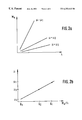
- FIG. 2 a is a plot of drive torque versus slip for different coefficients of friction
- FIG. 2 b is a plot of coefficient of friction versus MA/ 80 ;
- FIG. 3 is a block diagram of the traction controller
- FIG. 4 a is a time plot of the slip dependent and load dependent coefficients of friction
- FIG. 4 b is a time plot of the comber
- FIG. 4 c is a time plot of the correction time
- FIG. 5 is a computer flow diagram for determining maximum engine torque from actual engine torque.
- FIG. 6 is a computer flow diagram for determining the increased slip requirement.
- FIG. 1 shows an engine control system which influences the metering of fuel, the ignition angle and/or the supply of air to the internal combustion engine via the output lines 12 , 14 and/or 16 .
- input lines 24 to 26 are led from measuring devices 28 to 30 to the control system 10 , which measuring devices 28 to 30 detect the operating variables, essential for control, of the internal combustion engine and/or vehicle.
- the engine control system 10 is connected to a traction controller 36 via the lines 32 and 34 , which are part of a communication system.
- the input lines leading to the traction controller 36 are at least the input lines 38 , 40 , 42 and 44 of measuring devices 46 , 48 , 50 and 52 for detecting the speeds of revolution of the wheels of the vehicle, and, if appropriate, a line (not shown) from a steering angle sensor.
- the tendency of at least one drive wheel to slip is identified, in a manner known per se, as a function of the speeds of revolution of the wheels, and the maximum drive torque MAmax which can be transmitted is calculated.
- this maximum drive torque which can be transmitted is weighted both at the start of, and during, the traction control with the identified coefficient of friction and transmitted to the engine control system 10 as a desired torque value Mmotmax via the line 32 .
- the desired value determined by the traction control system 36 is set by correspondingly influencing the supply of air, by correcting the ignition angle and/or by suppressing individual injections.
- the engine torque which is output is calculated from operating variables of the internal combustion engine (e.g.
- the engine speed and air flow are transmitted to the traction controller 36 via the line 34 .
- the result is a control of the drive slip to a prescribed desired value by influencing the engine torque of the internal combustion engine.
- the engine torque which is output is derived from the value of the air flow rate.
- This coefficient of friction is referred to below as the slip-dependent coefficient of friction ⁇ s, in contrast to the coefficient of friction which is designated below as the load-dependent coefficient of friction ⁇ L and which constitutes the coefficient of friction which is set by the engine, and thus by the driver, and is independent of slip.
- the load-dependent coefficient of friction ⁇ L is calculated from the quotient of the difference between the drive torque MA and the rotational acceleration resistance torque MWBR (corresponds essentially to the product of the moment of inertia and the acceleration) and the product of the vehicle-specific data (vertical force of the drive axle and wheel radius).
- FIG. 3 shows an overview block diagram of the traction controller 36 in order to illustrate the procedure according to the invention.
- the calculated drive torque MA is transmitted to a division point 104 via the line 102 , to the calculation block 108 for the slip-dependent coefficient of friction ⁇ s via the line 106 and to the calculation block 112 for the load-dependent coefficient of friction ⁇ s via the line 110 .
- a block 114 is provided to which the lines 38 , 40 , 42 and 44 are led in order to estimate the average speed of the vehicle V FIG and to determine the average actual slip ⁇ at the driven wheels.
- the calculated slip value ⁇ is conducted to the calculation block 108 via the line 116 and to the division point 104 via the line 118 .
- the average speed of the vehicle is conducted via the line 120 to a calculation block 122 for calculating the rotational acceleration resistance torque MWBR, and via a line 124 to the calculation block 126 for identifying the increased slip requirement ⁇ erf.
- the speed of revolution signals of the nondriven wheels are conducted to a calculation block 128 on the lines 38 and 40 , which calculation block 128 determines entry into a bend by reference to the difference between the two values.
- This information is transmitted by the calculation block 128 to the actual traction controller 132 via a line 130 .
- a value which corresponds to the acceleration resistance torque MWBR is conducted from the calculation block 122 to the calculation unit 108 via the line 134 and to the calculation block 112 via the line 136 .
- the quotient of the drive torque MA and slip ⁇ is formed and conducted to the calculation block 108 via the line 138 .
- the line 140 on which a measure of the increased slip requirement ⁇ erf is transmitted, is also led to the calculation block 108 .
- the slip-dependent coefficient of friction ⁇ s identified in the calculation block 108 is conducted to the actual traction controller 132 via the line 142 and to the calculation block 146 via the line 144 .
- a measure of the load-dependent coefficient of friction ⁇ L is transmitted to the calculation block 146 on line 148 .
- the calculation block 146 determines a slip requirement ⁇ erf which is possibly increased as a result of the tires used, and transmits a corresponding signal to the calculation block 126 via the line 150 . If a steering angle sensor 131 is provided, as an alternate to block 128 a corresponding line is led to the actual traction controller 132 .
- the traction controller 132 whose output line forms the line 32 carries out the control of the drive slip, with the maximum drive torque MAmax which can be transmitted, or the engine torque Mmot to be set, being specified.
- the traction controller 132 identifies a rebound in the torque (MA Mmot) before the traction control is initiated as a function of the slip-dependent coefficient of friction ⁇ s which is conducted via the line 142 when the vehicle is traveling straight ahead, when block 128 detects entry into a bend or when the vehicle is traveling around a bend.
- ⁇ s b+a *( MA ⁇ MWBR )/( ⁇ erf )
- ⁇ s is the slip-dependent coefficient of friction
- b is the section of the axis
- a is the gradient of the selected straight line
- MA is the actual drive torque
- MWBR is the acceleration resistance torque
- ⁇ is the actual slip
- ⁇ erf is the increased slip requirement
- This slip-dependent coefficient of friction ⁇ s is evaluated by the traction controller 132 in order to determine the rebound in the torque.
- Constant factors for traveling straight ahead and for traveling through bends and entering bends, respectively with a high or low coefficient of friction are prescribed experimentally (when the vehicle begins to become unstable, which is detected by comparing the sum of the interfering moments (equivalent mass) with a prescribed limit value).
- the difference between the traveling speeds of the nondriven wheels is detected and compared with a limit value. If the difference exceeds this limit value, it is detected that the vehicle is traveling through a bend and an appropriate constant factor is prescribed.
- the constant factors are lowered if the coefficient of friction lies below a limit value.
- the constant factor for traveling straight ahead is greater than that for entering a bend.
- the specific maximum drive torque which can be transmitted is set, as a function of the identified coefficient of friction ⁇ s , preferably at the start of the actual traction control if excessive slip has been detected at the drive wheels.
- the slip-dependent coefficient of friction ⁇ s is dependent on the travel speed V FIG and the types of tires used.
- the travel speed dependence is represented in the publication by Heiner Bubb, page 33, FIG. 5 .
- ⁇ s generally decreases and the slip requirement ⁇ erf increases as the travel speed increases. Therefore, the travel speed is conducted to the calculation block 126 via the line 124 .
- the travel speed is compared with a prescribed threshold value by means of which the dependence of the slip requirement on the travel speed, which is described in approximate terms, can be prescribed.
- two different travel speed-dependent straight lines with different gradients are prescribed for the increased slip requirement ⁇ erf. These straight lines are determined experimentally. If, for example, the travel speed exceeds the threshold value, the system is switched over to a straight-line equation with an increased gradient.
- the calculation block 146 the calculated, slip-dependent coefficient of friction ⁇ L is compared with the load-dependent coefficient of friction ⁇ L which was identified on the basis of the drive torque MA.
- a time counter is started. If the latter reaches its maximum value and if the slip-dependent coefficient of friction continues to be smaller than the load-dependent coefficient of friction, a marker for the increased slip requirement is set and this marker is conducted to the calculation block 126 . By setting the marker, the gradient of the prescribed speed-dependent straight-line equations is also switched over in a speed-dependent way. This procedure is based on the knowledge that when there is an increased slip requirement the drive torque is opposed by an excessively large slip and thus the calculated slip-dependent coefficient of friction drops to excessively small values. This behavior characterizes an increased slip requirement. In this way, the calculated coefficient of friction is corrected in accordance with the actual physical coefficient of friction.
- the filtering is also carried out preferably with a PT 1 element.
- a second pair of speed-dependent straight-line equations which also have different gradients depending on the speed, is prescribed for the state with increased slip requirement.
- FIG. 4 a shows the time-dependent variation of the slip-dependent coefficient of friction (continuous line) and of the load-dependent coefficient of friction (broken line).
- the load-dependent coefficient of friction is increased by the drive torque being increased by the driver.
- the calculated slip-dependent coefficient of friction drops until, at the time T 0 , it becomes smaller than the load-dependent coefficient of friction.
- the time counter is started. The latter reaches a maximum value at the time T 1 , the slip-dependent coefficient of friction having remained smaller than the load-dependent one.
- the marker is set according to FIG. 4 c and the slip-dependent coefficient of friction ⁇ L is corrected so that it essentially corresponds to the physical one again.
- FIGS. 5 and 6 show the illustrated procedure as a flow diagram.
- FIG. 5 shows the calculation of the maximum drive torque which can be transmitted while the procedure for determining the increased slip requirement ⁇ erf is outlined in FIG. 6 .
- the wheel speeds vrad and the actual engine torque Mmot are read in.
- the average vehicle speed vfzg, the drive torque MA and the average actual slip ⁇ act are calculated.
- the acceleration resistance torque MWBR is calculated, and in the subsequent step 206 the quotient Q is formed from the drive torque MA and actual slip ⁇ act.
- the load-dependent coefficient of friction ⁇ L is calculated, as illustrated above, as a function of the drive torque MA and of the acceleration resistance torque MWBR, and in step 210 the additional slip requirement ⁇ erf which is identified in accordance with the procedure according to FIG.
- step 212 the slip-dependent coefficient of friction ⁇ s is formed as a function of the drive torque MA, the acceleration resistance torque MWBR, the actual slip of the additional slip requirement and the quotient of the drive torque and actual slip.
- step 214 the maximum drive torque MAmax or engine torque Mmatmax which can be transmitted is formed on the basis of the slip-dependent coefficient of friction and of the prescribed constant factor, as illustrated above, and the part of the program is terminated.
- step 300 the current values of the load-dependent coefficient of friction, the slip-dependent coefficient of friction and the average vehicle speed are read in.
- step 302 it is tested whether the slip-dependent coefficient of friction is smaller than the load-dependent coefficient of friction. If this is not the case, according to step 304 the counter T is set to 0 and in the subsequent inquiry step 306 the average speed of the vehicle V FIG is compared with a prescribed limit value v 0 .
- step 302 If the result of step 302 was that the slip-dependent coefficient of friction ⁇ s is smaller than the load-dependent coefficient of friction ⁇ L , the counter T is increased by 1 in step 308 and an inquiry as to its maximum value Tmax is made in the subsequent inquiry step 310 . If the counter is below its prescribed maximum value, the part of the program is terminated and started again at prescribed times. If the counter has reached its maximum value, in step 312 the marker is set to 1 for an increased slip requirement and the system proceeds with step 306 .
- the filter function illustrated above is realized by means of the illustrated incrementing of the counter according to steps 308 and 310 .
- step 306 it is tested whether the average speed of the vehicle is lower than or equal to the prescribed threshold value v 0 . If this is the case, in the subsequent step 314 it is tested whether the marker has been set to the value 1 . This leads, in step 316 , to the additional slip requirement ⁇ erf being identified as a function of the speed of the vehicle V FIG using a first proportionality constant K 1 . Afterwards, the part of the program is terminated.
- step 318 the additional slip requirement is determined as a function of the speed of the vehicle using a proportionality constant K 2 and the part of the program is terminated.
- step 322 the additional slip requirement is calculated in step 322 as a function of the speed of the vehicle using the proportionality constant K 3 . If the marker is not 1 in this operating state, according to step 324 the additional slip requirement is obtained as a function of the speed of the vehicle using the proportionality constant K 4 .
- the constant K 3 is larger in absolute value than the constant K 1 and this is in turn larger than the constant K 4 .
- the constant K 2 is the smallest in absolute value.
- the part of the program illustrated in FIG. 6 merely illustrates the setting of the marker to the value 1 , that is to say the identification of the increased slip requirement.
- Resetting the marker to the value 0 can be realized in different ways. It has become apparent that automatic initialization of the marker with the value 0 at the start of each operating cycle with “ignition on” is sufficient.
- Another advantageous way of resetting the marker to the value 0 results from an excessively large traction control deviation of the traction controller which occurs if the slip-dependent coefficient of friction is too inaccurate as a result of the increased slip requirement which has been set.
Landscapes
- Engineering & Computer Science (AREA)
- Transportation (AREA)
- Mechanical Engineering (AREA)
- Chemical & Material Sciences (AREA)
- Combustion & Propulsion (AREA)
- Control Of Vehicle Engines Or Engines For Specific Uses (AREA)
- Regulating Braking Force (AREA)
- Electric Propulsion And Braking For Vehicles (AREA)
- Control Of Driving Devices And Active Controlling Of Vehicle (AREA)
- Auxiliary Drives, Propulsion Controls, And Safety Devices (AREA)
Applications Claiming Priority (2)
| Application Number | Priority Date | Filing Date | Title |
|---|---|---|---|
| DE4430108A DE4430108B4 (de) | 1994-08-25 | 1994-08-25 | Antriebsschlupfregelsystem |
| DE4430108 | 1994-08-25 |
Publications (1)
| Publication Number | Publication Date |
|---|---|
| US6253142B1 true US6253142B1 (en) | 2001-06-26 |
Family
ID=6526506
Family Applications (1)
| Application Number | Title | Priority Date | Filing Date |
|---|---|---|---|
| US08/519,234 Expired - Lifetime US6253142B1 (en) | 1994-08-25 | 1995-08-25 | Traction control system for motor vehicles |
Country Status (5)
| Country | Link |
|---|---|
| US (1) | US6253142B1 (de) |
| JP (1) | JPH0886231A (de) |
| KR (1) | KR100381491B1 (de) |
| DE (1) | DE4430108B4 (de) |
| FR (1) | FR2723890B1 (de) |
Cited By (6)
| Publication number | Priority date | Publication date | Assignee | Title |
|---|---|---|---|---|
| US20030209377A1 (en) * | 2002-03-28 | 2003-11-13 | Thomas Sauter | Reduction in TCS control frequency when cornering on a road surface having a low coefficient of friction |
| US20040130208A1 (en) * | 2001-01-27 | 2004-07-08 | Conrad Muller | Torque control system dependent on wheel load in a drive mechanism |
| US20050102087A1 (en) * | 2003-11-10 | 2005-05-12 | Mamoru Sawada | Vehicle behavior estimating device and vehicle behavior controlling device |
| US20080121323A1 (en) * | 2004-11-03 | 2008-05-29 | Teuvo Karppinen | Vehicle Tyre |
| US20080315622A1 (en) * | 2005-12-27 | 2008-12-25 | Kazunori Oda | Wheel Pant Device For a Vehicle and Control Method Thereof |
| US20110125382A1 (en) * | 2009-11-25 | 2011-05-26 | Bayerische Motoren Werke Aktiengesellschaft | Coefficient of Friction Based Limitation of the Torque of a Vehicle Control Loop |
Families Citing this family (15)
| Publication number | Priority date | Publication date | Assignee | Title |
|---|---|---|---|---|
| US5865512A (en) * | 1996-09-05 | 1999-02-02 | Caterpillar Inc. | Method and apparatus for modifying the feedback gains of a traction control system |
| DE19704841A1 (de) | 1997-02-08 | 1998-08-13 | Itt Mfg Enterprises Inc | Verfahren und Vorrichtung zur Regelung der Längsdynamik eines Fahrzeugs |
| DE19734112B4 (de) * | 1997-08-07 | 2007-12-27 | Robert Bosch Gmbh | Verfahren und Vorrichtung zur Antriebsschlupfregelung bei Kraftfahrzeugen |
| DE19849322B4 (de) * | 1998-10-26 | 2014-09-11 | Robert Bosch Gmbh | Verfahren und Vorrichtung zur Schätzung des maximal absetzbaren Antriebsmoments bei einem Kraftfahrzeug |
| DE19855332A1 (de) * | 1998-12-01 | 2000-06-08 | Daimler Chrysler Ag | Verfahren und Vorrichtung zum Bestimmen von Kraftschluß und Kraftschlußgrenze bei Fahrzeugreifen |
| DE19900356B4 (de) * | 1999-01-07 | 2006-05-11 | Robert Bosch Gmbh | Verfahren und Vorrichtung zur Antriebsschlupfregelung |
| DE19933084B4 (de) | 1999-07-15 | 2014-01-09 | Robert Bosch Gmbh | Verfahren und Vorrichtung zur Steuerung des Schlupfes eines Fahrzeugrades |
| DE19933087B4 (de) * | 1999-07-15 | 2013-07-11 | Robert Bosch Gmbh | Verfahren und Vorrichtung zur Steuerung einer Antriebseinheit eines Fahrzeuges |
| DE10019137A1 (de) | 2000-04-18 | 2001-10-25 | Bosch Gmbh Robert | Schlupfregelsystem für ein Fahrzeug |
| US6285280B1 (en) * | 2000-06-26 | 2001-09-04 | Robert Bosch Corporation | Method for detecting a deflated tire on a vehicle |
| JP3999448B2 (ja) * | 2000-07-17 | 2007-10-31 | トヨタ自動車株式会社 | 車輌用トラクション制御装置 |
| DE10065527B4 (de) * | 2000-12-28 | 2009-03-05 | Robert Bosch Gmbh | Verfahren und System zum Begrenzen des Motordrehmoments von Fahrzeugen |
| DE102010038563A1 (de) * | 2010-07-28 | 2012-02-02 | Robert Bosch Gmbh | Verfahren zum Reduzieren des Antriebsschlupfes bei Fahrzeugen mit mehreren Motoren |
| FR3013666B1 (fr) * | 2013-11-28 | 2017-04-14 | Renault Sas | Systeme de controle de motricite pour vehicule automobile utilisant un signal de correction en rampe extrait d'une cartographie et procede de controle correspondant |
| DE102019208459A1 (de) * | 2019-06-11 | 2020-12-17 | Zf Friedrichshafen Ag | Bestimmung eines Reibwerts |
Citations (15)
| Publication number | Priority date | Publication date | Assignee | Title |
|---|---|---|---|---|
| WO1989003780A1 (en) | 1987-10-22 | 1989-05-05 | Robert Bosch Gmbh | PROCESS FOR CONTINUOUS DETERMINATION OF THE ADHESION COEFFICIENT $G(m) AND/OR THE SLOPE Kmu of the mu SLIP CURVE |
| US4947332A (en) * | 1989-09-27 | 1990-08-07 | General Motors Corporation | Road surface estimation |
| US5010982A (en) * | 1988-08-06 | 1991-04-30 | Robert Bosch Gmbh | Method and apparatus for improving vehicle traction and roadability |
| US5018595A (en) * | 1989-07-11 | 1991-05-28 | Nippondenso Co., Ltd. | Traction control system |
| EP0444803A1 (de) | 1990-03-02 | 1991-09-04 | Lucas Industries Public Limited Company | Verfahren und Vorrichtung zur Steuerung des Radschlupfes |
| US5090511A (en) * | 1989-08-14 | 1992-02-25 | General Motors Corporation | Adaptive vehicle traction control system |
| US5103928A (en) | 1989-11-18 | 1992-04-14 | Mercedes-Benz Ag | Drive slip controlling method |
| DE4218034A1 (de) | 1992-06-02 | 1993-12-09 | Porsche Ag | Verfahren zur Bestimmung eines Kraftschlußpotentials eines Kraftfahrzeuges |
| DE4338587A1 (de) | 1992-11-12 | 1994-05-19 | Ford Werke Ag | Verfahren zum Schätzen des Greifverhaltens einer Fahrbahnoberfläche gegenüber den Rädern eines Kraftfahrzeuges |
| DE4239711A1 (de) | 1992-11-26 | 1994-06-01 | Bosch Gmbh Robert | Verfahren und Vorrichtung zur Steuerung eines Fahrzeugs |
| US5320422A (en) * | 1991-02-14 | 1994-06-14 | Mazda Motor Corporation | Slip control device for vehicle wheel |
| US5351192A (en) * | 1991-12-25 | 1994-09-27 | Mazda Motor Corporation | Slippage control system using estimated road surface resistances |
| US5373447A (en) * | 1992-01-10 | 1994-12-13 | Lucas Industries | Method of and apparatus for vehicle traction control by detecting wheel spin |
| US5394329A (en) * | 1992-04-28 | 1995-02-28 | Lucas Industries Public Limited Company | Method of and apparatus for estimating surface friction |
| US5459661A (en) * | 1992-06-22 | 1995-10-17 | Toyota Jidosha Kabushiki Kaisha | Traction control apparatus in which a driving force is increased when a stalling condition is detected |
Family Cites Families (1)
| Publication number | Priority date | Publication date | Assignee | Title |
|---|---|---|---|---|
| DE3741247C1 (de) * | 1987-12-05 | 1989-05-24 | Daimler Benz Ag | Verfahren zur Anpassung von Schlupfschwellwerten fuer ein Antriebsschlupf- und/oder Bremsschlupf-Regelsystem an die Bereifung eines Kraftfahrzeuges |
-
1994
- 1994-08-25 DE DE4430108A patent/DE4430108B4/de not_active Expired - Lifetime
-
1995
- 1995-08-24 KR KR1019950026294A patent/KR100381491B1/ko not_active IP Right Cessation
- 1995-08-24 JP JP7216225A patent/JPH0886231A/ja active Pending
- 1995-08-25 US US08/519,234 patent/US6253142B1/en not_active Expired - Lifetime
- 1995-08-25 FR FR9510099A patent/FR2723890B1/fr not_active Expired - Fee Related
Patent Citations (15)
| Publication number | Priority date | Publication date | Assignee | Title |
|---|---|---|---|---|
| WO1989003780A1 (en) | 1987-10-22 | 1989-05-05 | Robert Bosch Gmbh | PROCESS FOR CONTINUOUS DETERMINATION OF THE ADHESION COEFFICIENT $G(m) AND/OR THE SLOPE Kmu of the mu SLIP CURVE |
| US5010982A (en) * | 1988-08-06 | 1991-04-30 | Robert Bosch Gmbh | Method and apparatus for improving vehicle traction and roadability |
| US5018595A (en) * | 1989-07-11 | 1991-05-28 | Nippondenso Co., Ltd. | Traction control system |
| US5090511A (en) * | 1989-08-14 | 1992-02-25 | General Motors Corporation | Adaptive vehicle traction control system |
| US4947332A (en) * | 1989-09-27 | 1990-08-07 | General Motors Corporation | Road surface estimation |
| US5103928A (en) | 1989-11-18 | 1992-04-14 | Mercedes-Benz Ag | Drive slip controlling method |
| EP0444803A1 (de) | 1990-03-02 | 1991-09-04 | Lucas Industries Public Limited Company | Verfahren und Vorrichtung zur Steuerung des Radschlupfes |
| US5320422A (en) * | 1991-02-14 | 1994-06-14 | Mazda Motor Corporation | Slip control device for vehicle wheel |
| US5351192A (en) * | 1991-12-25 | 1994-09-27 | Mazda Motor Corporation | Slippage control system using estimated road surface resistances |
| US5373447A (en) * | 1992-01-10 | 1994-12-13 | Lucas Industries | Method of and apparatus for vehicle traction control by detecting wheel spin |
| US5394329A (en) * | 1992-04-28 | 1995-02-28 | Lucas Industries Public Limited Company | Method of and apparatus for estimating surface friction |
| DE4218034A1 (de) | 1992-06-02 | 1993-12-09 | Porsche Ag | Verfahren zur Bestimmung eines Kraftschlußpotentials eines Kraftfahrzeuges |
| US5459661A (en) * | 1992-06-22 | 1995-10-17 | Toyota Jidosha Kabushiki Kaisha | Traction control apparatus in which a driving force is increased when a stalling condition is detected |
| DE4338587A1 (de) | 1992-11-12 | 1994-05-19 | Ford Werke Ag | Verfahren zum Schätzen des Greifverhaltens einer Fahrbahnoberfläche gegenüber den Rädern eines Kraftfahrzeuges |
| DE4239711A1 (de) | 1992-11-26 | 1994-06-01 | Bosch Gmbh Robert | Verfahren und Vorrichtung zur Steuerung eines Fahrzeugs |
Non-Patent Citations (1)
| Title |
|---|
| Bubb, Heiner, "Ein Verfahren zur Bestimmung des Kraftschlusses zwischen Rad und strasse während der Fahrt" Automobiltecnische Zeitschrift, 83 (1981) 1, pp.31-36, Jan. 1981. |
Cited By (10)
| Publication number | Priority date | Publication date | Assignee | Title |
|---|---|---|---|---|
| US20040130208A1 (en) * | 2001-01-27 | 2004-07-08 | Conrad Muller | Torque control system dependent on wheel load in a drive mechanism |
| US20030209377A1 (en) * | 2002-03-28 | 2003-11-13 | Thomas Sauter | Reduction in TCS control frequency when cornering on a road surface having a low coefficient of friction |
| US6810981B2 (en) * | 2002-03-28 | 2004-11-02 | Robert Bosch Gmbh | Reduction in TCS control frequency when cornering on a road surface having a low coefficient of friction |
| US20050102087A1 (en) * | 2003-11-10 | 2005-05-12 | Mamoru Sawada | Vehicle behavior estimating device and vehicle behavior controlling device |
| US7328097B2 (en) | 2003-11-10 | 2008-02-05 | Denso Corporation | Vehicle behavior estimating device and vehicle behavior controlling device |
| US20080121323A1 (en) * | 2004-11-03 | 2008-05-29 | Teuvo Karppinen | Vehicle Tyre |
| US20080315622A1 (en) * | 2005-12-27 | 2008-12-25 | Kazunori Oda | Wheel Pant Device For a Vehicle and Control Method Thereof |
| US7988220B2 (en) * | 2005-12-27 | 2011-08-02 | Toyota Jidosha Kabushiki Kaisha | Wheel pant device for a vehicle and control method thereof |
| US20110125382A1 (en) * | 2009-11-25 | 2011-05-26 | Bayerische Motoren Werke Aktiengesellschaft | Coefficient of Friction Based Limitation of the Torque of a Vehicle Control Loop |
| US8504273B2 (en) | 2009-11-25 | 2013-08-06 | Bayerische Motoren Werke Aktiengesellschaft | Coefficient of friction based limitation of the torque of a vehicle control loop |
Also Published As
| Publication number | Publication date |
|---|---|
| FR2723890A1 (fr) | 1996-03-01 |
| KR960007249A (ko) | 1996-03-22 |
| DE4430108A1 (de) | 1996-02-29 |
| KR100381491B1 (ko) | 2003-07-12 |
| JPH0886231A (ja) | 1996-04-02 |
| FR2723890B1 (fr) | 1998-10-23 |
| DE4430108B4 (de) | 2011-11-24 |
Similar Documents
| Publication | Publication Date | Title |
|---|---|---|
| US6253142B1 (en) | Traction control system for motor vehicles | |
| US5299131A (en) | Method of correcting the rotating speed of vehicle wheels sensed by wheel sensors | |
| US6182021B1 (en) | Tire air pressure warning device | |
| US5471386A (en) | Vehicle traction controller with torque and slip control | |
| EP1378411B1 (de) | Verfahren und Vorrichtung zur Ermittlung der Masse eines Kraftfahrzeugs sowie Verfahren und Vorrichtung zur Ermittlung der Fahrbahnneigung, unter Verwendung eines solchen Verfahrens | |
| US6456924B1 (en) | Method and device for controlling the slippage of a vehicle wheel | |
| US4984165A (en) | Method and apparatus for adapting slip threshold values for a propulsion slip and/or braking slip control system to the tires of a motor vehicle | |
| KR20000068450A (ko) | 차량질량 결정방법 및 장치 | |
| JPH1172372A (ja) | 自動車とくに実用自動車の車両質量を表わす質量値を求める方法および装置 | |
| CN108791276B (zh) | 一种轮胎侧向力线性/非线性工作状态快速判断方法 | |
| US20030144777A1 (en) | System and method for monitoring the vehicle dynamics of a motor vehicle | |
| JP3351205B2 (ja) | 車両の安全走行制御装置及び制御方法 | |
| KR19990071465A (ko) | 차량운동을나타내는운동량을조정하기위한방법및장치 | |
| CN111114551B (zh) | 一种车辆坡道坡度识别方法和装置 | |
| JP4728550B2 (ja) | 自動車のトラクション制御(asr)方法及び装置 | |
| US9387843B2 (en) | Method and device for controlling the traction slip of driven wheels of a vehicle with the engine rotational speed as manipulated variable | |
| JP2003531763A (ja) | 自動車のステアリング装置用ミスアラインメント検出システム | |
| JP4190620B2 (ja) | 自動車における駆動滑り制御方法および装置 | |
| JP3299682B2 (ja) | 初期補正係数演算装置 | |
| US6061622A (en) | Circuit configuration for controlling torque transmitted between driven wheels of a motor vehicle and a roadway | |
| KR20040091154A (ko) | 타이어 압력 손실의 검출을 개선하기 위한 오프로드 검출방법 및 그 장치 | |
| US6044320A (en) | Process and device for generating an error signal in a motor vehicle | |
| US6535809B1 (en) | Vehicle engine torque control with engine drag control mode | |
| KR20000068394A (ko) | 차량의 운동량 조절방법 및 장치 | |
| JPH07100451B2 (ja) | 動力舵取装置の操舵力制御装置 |
Legal Events
| Date | Code | Title | Description |
|---|---|---|---|
| AS | Assignment |
Owner name: ROBERT BOSCH GMBH, GERMANY Free format text: ASSIGNMENT OF ASSIGNORS INTEREST;ASSIGNORS:SAUTER, THOMAS;DAUBNER, PETER;REEL/FRAME:007633/0441 Effective date: 19950731 |
|
| STCF | Information on status: patent grant |
Free format text: PATENTED CASE |
|
| FEPP | Fee payment procedure |
Free format text: PAYOR NUMBER ASSIGNED (ORIGINAL EVENT CODE: ASPN); ENTITY STATUS OF PATENT OWNER: LARGE ENTITY |
|
| FPAY | Fee payment |
Year of fee payment: 4 |
|
| FPAY | Fee payment |
Year of fee payment: 8 |
|
| FPAY | Fee payment |
Year of fee payment: 12 |